Table of Contents
Advertisement
Quick Links
Advertisement
Table of Contents

Subscribe to Our Youtube Channel
Related Manuals for Patton SmartNode 1000 Series


Summary of Contents for Patton SmartNode 1000 Series
- Page 1 SmartNode 1000 and 2000 Series VoIP Media Gateways Getting Started Guide Sales Office: +1 (301) 975-1000 Technical Support: +1 (301) 975-1007 E-mail: support@patton.com WWW: www.patton.com Document Number: 13206U1-001 Rev. I Part Number: 07MDSN2000-GS Revised: October 19, 2006...
- Page 2 Patton Electronics Company, Inc. 7622 Rickenbacker Drive Gaithersburg, MD 20879 USA tel: +1 (301) 975-1000 fax: +1 (301) 869-9293 support: +1 (301) 975-1007 url: www.patton.com e-mail: support@patton.com Copyright Statement Copyright © 2003-2006, Patton Electronics Company. All rights reserved. Trademark Statement The terms SmartWare and SmartNode are trademarks of Patton Electronics Company.
-
Page 3: Table Of Contents
Contents Contents ................................. 3 Compliance Information ..........................9 Radio and TV Interference (FCC Part 15) ......................9 ..........................Declaration of Conformity Compliance ................................9 .................................9 Safety ................................9 PSTN Regulatory (SN1200 & SN1400) ......................9 PSTN Regulatory (SN1200 & SN1400) ......................9 FCC Part 68 (ACTA) Statement (SN2300 & SN2400 with T1V Card) ............10 Industry Canada Notice (SN2300 &... - Page 4 SmartNode 1000 and 2000 Series Getting Started Guide Contents Rear panel ...............................33 Expansion slots ............................33 On-board ports ............................33 Interface cards descriptions ............................35 IC-4FXS Gateway interface card for 4 analog FXS ports .................35 Front panel ...............................35 Ports ................................36 Description ...............................36 IC-4BRV 8-channel gateway interface card for ISDN BRI ................37 Front panel ...............................37...
- Page 5 SmartNode 1000 and 2000 Series Getting Started Guide Contents System model of the SmartNode 1000 and 2000 Series..................54 Voice routing.................................54 SmartNode deployment............................55 Customer premises gateway; multi-service providers ..................55 Small office or home office (SOHO) ......................55 Small and medium enterprise (SME) ......................56 Multi-service gateway/router for private enterprise networks ................58...
- Page 6 SmartNode 1000 and 2000 Series Getting Started Guide Contents Connecting cables..............................85 Installing the Ethernet cables ..........................85 Installing the BRI cables ..........................86 External S-Bus power supply ........................88 Installing the power cord ..........................90 SmartNode 2300 installation......................... 91 Hardware installation ............................93 Mounting the SmartNode 2300 ..........................93 Desktop installation ............................94...
- Page 7 SmartNode 1000 and 2000 Series Getting Started Guide Contents Safety Recommendation ............................135 Installing interface cards ............................136 Card locating screws ............................137 Getting Started with the SmartNode Device ....................139 Introduction ................................141 1. Configure IP address ............................142 Power connection and default configuration ....................142 Connect with the serial interface ........................142...
- Page 8 SmartNode 1000 and 2000 Series Getting Started Guide Contents Line power module ............................162 T1/E1 daughter card Hardware Interface (software selectable): .......................163 Indication LEDs ............................163 Identification of the SmartNode devices via SNMP.....................163 Cabling ............................... 165 Introduction ................................167 Serial console ...............................167 Ethernet 10Base-T and 100Base-T ........................168 V.35 and X.21..............................169...
-
Page 9: Compliance Information
Compliance Information Interference (FCC Part 15) and TV Radio This equipment generates and uses radio frequency energy, and if not installed and used properly—that is, in strict accordance with the manufacturer's instructions—may cause interference to radio and television recep- tion. This equipment has been tested and found to comply with the limits for a Class B computing device in accordance with the specifications in Subpart B of Part 15 of FCC rules, which are designed to provide reason- able protection from such interference in a commercial installation. -
Page 10: Fcc Part 68 (Acta) Statement (Sn2300 & Sn2400 With T1V Card)
SmartNode 1000 and 2000 Series Getting Started Guide Compliance Information • TBR 12 & 13 (with E1V Card) • AS/ACIF S016:2001 (with E1V Card) FCC Part 68 (ACTA) Statement (SN2300 & SN2400 with T1V Card) This equipment complies with Part 68 of FCC rules and the requirements adopted by ACTA. On the bottom side of this equipment is a label that contains—among other information—a product identifier in the format US: AAAEQ##TXXXX. -
Page 11: Service
SmartNode 1000 and 2000 Series Getting Started Guide Compliance Information Service All warranty and non-warranty repairs must be returned freight prepaid and insured to Patton Electronics. For more information about warranty service, refer to “Warranty Service and Returned Merchandise Authoriza- tions (RMAs)”... - Page 12 SmartNode 1000 and 2000 Series Getting Started Guide Compliance Information Compliance...
-
Page 13: About This Guide
About this guide This guide provides hardware information concerning SmartNode devices and their interface cards. The instal- lation of the cards and the cabling of the devices are also described. The goal is to enable you to install such devices, alone or under supervision. The information included in this guide consists of: •... -
Page 14: Structure
SmartNode 1000 and 2000 Series Getting Started Guide About this guide Structure This guide contains the following chapters and appendices: • Chapter 1 provides information about SmartNode features and capabilities • Chapter 2 contains an overview describing SmartNode operation • Chapter 3 lists items and information that should be at hand before you begin installing the SmartNode device... -
Page 15: Safety When Working With Electricity
SmartNode 1000 and 2000 Series Getting Started Guide About this guide The shock hazard symbol and CAUTION heading indicate a potential electric shock hazard. Strictly follow the instructions to avoid property damage caused by electric shock. The alert symbol and CAUTION heading indicate a potential haz- ard. -
Page 16: Preventing Electrostatic Discharge Damage
SmartNode 1000 and 2000 Series Getting Started Guide About this guide In accordance with the requirements of council directive 2002/96/EC on Waste of Electrical and Electronic Equipment (WEEE), ensure that at end-of-life you separate this product from other waste and scrap and deliver to the WEEE collection system in your country for recycling. -
Page 17: Typographical Conventions Used In This Document
SmartNode 1000 and 2000 Series Getting Started Guide About this guide Typographical conventions used in this document This section describes the typographical conventions and terms used in this guide. General conventions The procedures described in this manual use the following text conventions: Table 1. - Page 18 SmartNode 1000 and 2000 Series Getting Started Guide About this guide Table 2. Mouse conventions Convention Meaning Drag This word means to place the cursor and then hold down the left or right mouse but- ton (as instructed in the procedure) as you move the mouse to a new location. When you have moved the cursor to the desired location, you can release the mouse button.
-
Page 19: General Information
Chapter 1 General Information Chapter contents Introduction ................................21 SmartNode 1200 description..........................22 Front panel ..............................22 Rear panel ...............................23 Clock mode configuration (Model SN1200) ....................25 SmartNode 1400 description..........................25 Front panel ..............................25 Rear panel ...............................26 Clock mode configuration (Model SN1400) ....................27 SmartNode 2300 description..........................28 Front panel ..............................29... - Page 20 SmartNode 1000 and 2000 Series Getting Started Guide 1 • General Information S-Bus line power ............................45 Line power jumper settings ........................45 Jumper settings for IC-4BRV-8V ......................46 IC-4BRV-8VR—8-channel gateway interface card for ISDN BRI with hardware bypass (emergency) relay ..46 IC-E1V 30-channel E1 gateway interface card for ISDN PRI .................47 Front panel...
-
Page 21: Introduction
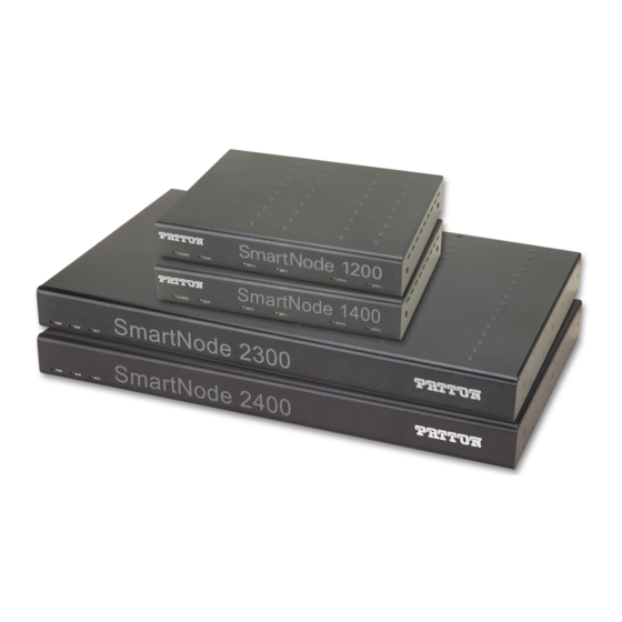
This guide describes installing the SmartNode 1000 Series and 2000 Series devices. The SmartNode 1000 series are compact IP access devices for applications in SOHO or branch office environ- ments. Two models are currently available with 2 or 4 voice over IP channels (see figure... -
Page 22: Smartnode 1200 Description
SmartNode 1000 and 2000 Series Getting Started Guide 1 • General Information SmartNode 1200 description The SmartNode Model 1200 (see figure 2) is a compact voice/data access device that supports two voice chan- nels. The user interfaces consist of one ISDN BRI port and one Ethernet 10Base-T port. Network access com- prises one ISDN BRI port and one Ethernet 10Base-T port. -
Page 23: Rear Panel
SmartNode 1000 and 2000 Series Getting Started Guide 1 • General Information Rear panel The SmartNode 1200 rear panel includes the following LEDs for at-a-glance status display (see figure • LINK LEDs that indicate the status of the Ethernet connections •... - Page 24 SmartNode 1000 and 2000 Series Getting Started Guide 1 • General Information Table 3. SmartNode 1200 port description (Continued) Port Description ISDN BRI RJ-45 socket that connects the SmartNode with an ISDN S-Bus, e.g. a PBX. BRI 1 The L2 LED to the left of the connector is lit when the port is connected correctly to an ISDN S (Phone) active ISDN device (Layer 1 is up).
-
Page 25: Clock Mode Configuration (Model Sn1200)
SmartNode 1000 and 2000 Series Getting Started Guide 1 • General Information Clock mode configuration (Model SN1200) The following table shows which clock mode configurations are allowed for the SmartNode 1200 and which port is used as the clock source. Table 5. -
Page 26: Rear Panel
SmartNode 1000 and 2000 Series Getting Started Guide 1 • General Information Figure 6. SmartNode 1400 front panel See chapter 11, “Monitoring Status” on page 151 for more information on LED indications. Rear panel The SmartNode 1400 rear panel includes the following LEDs for at-a-glance status display (see figure •... -
Page 27: Clock Mode Configuration (Model Sn1400)
SmartNode 1000 and 2000 Series Getting Started Guide 1 • General Information Table 6. SmartNode 1400 port description (Continued) Port Description 10Base-T Ethernet RJ-45 socket that connects the SmartNode with an Ethernet device, ETH 1 10Base-T (LAN) usually a LAN hub or switch. ETH 1 is a host port; it can be connected with a straight- through wired cable to a hub or a cross-over cable to a host (PC) port. -
Page 28: Smartnode 2300 Description
SmartNode 1000 and 2000 Series Getting Started Guide 1 • General Information Table 7. Clock-modes and clock-sources for the SmartNode 1400 Port 0 Port 1 Clock Source Clock Mode Clock Mode Slave (User) Master (Net) Port 0. Clock is taken from port 0 if available. Otherwise it is generated inter- nally. -
Page 29: Front Panel
SmartNode 1000 and 2000 Series Getting Started Guide 1 • General Information Figure 8. Model 2300 (front and rear views shown) Front panel The SmartNode 2300 rear panel includes the PWR, RUN, and ACT LEDs that indicate the status of the device (see figure 9). -
Page 30: Expansion Slots
SmartNode 1000 and 2000 Series Getting Started Guide 1 • General Information board interfaces (see appendix B, “Cabling” on page 165 for connection cable and appendix C, “Port pin-outs” on page 177 for pin-out data). Figure 10. SmartNode 2300 rear panel Expansion slots The slots labeled SLOT 1, SLOT 2, and SLOT 3 (see figure... - Page 31 SmartNode 1000 and 2000 Series Getting Started Guide 1 • General Information In addition, two other elements the—Reset button and power input socket—are available on the rear panel of a SmartNode 1200 as described in table Table 10. SmartNode 2300 Reset button and power line socket on rear panel Element Description Reset button...
-
Page 32: Smartnode 2400 Description
SmartNode 1000 and 2000 Series Getting Started Guide 1 • General Information SmartNode 2400 description The SmartNode Model 2400 (see figure 11) is a powerful multi-service access device. The 19-in. aluminum chassis can be rack-mounted, and provides three expansion slots for interface cards. Note If you will be mounting the SmartNode 2400 in a 19-in. -
Page 33: Rear Panel
SmartNode 1000 and 2000 Series Getting Started Guide 1 • General Information Rear panel The SmartNode 2400 rear panel is depicted in figure 13. There are four expansion slots for optional interface cards, and four board-mounted sockets. There are four expansion slots for optional interface cards, and four board-mounted sockets. - Page 34 SmartNode 1000 and 2000 Series Getting Started Guide 1 • General Information Table 11. SmartNode 2400 port description (Continued) Port Description RS-232 RJ-45 connector that connects the SmartNode with a serial terminal such as a Console PC or workstation with a RS-232 interface, with the following settings: (RS-232) 9600 bps, no parity, 8 bit, 1 stop bit, 1 start bit •...
-
Page 35: Interface Cards Descriptions
SmartNode 1000 and 2000 Series Getting Started Guide 1 • General Information Interface cards descriptions The following interface cards (see figure 14) are available for use with the SmartNode 2000 Series devices: • IC-4FXS—Gateway interface card for 4 analog FXS ports (see page 35) •... -
Page 36: Ports
SmartNode 1000 and 2000 Series Getting Started Guide 1 • General Information Figure 15. IC-4FXS Ports The card provides the four FXS ports whose details are tabulated in table 13. Protector circuits protect the ports from high voltage surges. See appendix A, “Specifications”... -
Page 37: Ic-4Brv 8-Channel Gateway Interface Card For Isdn Bri
SmartNode 1000 and 2000 Series Getting Started Guide 1 • General Information page 125). This line power module provides the loop voltage (-48 VDC) and the input to the ring voltage generator. IC-4BRV 8-channel gateway interface card for ISDN BRI The IC-4BRV is a PMC standard compatible interface card for the SmartNode 2000 series. -
Page 38: Description
SmartNode 1000 and 2000 Series Getting Started Guide 1 • General Information Table 14. IC-4BRV port description Port Description BRI 1 ISDN BRI RJ-45 socket that connects the SmartNode with an ISDN terminal over an S or S/T inter- face. BRI 2 may be used as a fallback in conjunction with BRI 1. See ‘Hardware Bypass’ below. BRI 2 ISDN BRI RJ-45 socket that connects the SmartNode with an ISDN device over an S or S/T inter- face. -
Page 39: Network Integration
SmartNode 1000 and 2000 Series Getting Started Guide 1 • General Information Calls from an ISDN terminal are then automatically connected to the LE of the ISDN network. The bypass may also be activated manually. Figure 17 shows a typical fallback situation when the bypass is activated: the numbers in the boxes refer to the IC-4BRV’s four BRI port numbers. - Page 40 SmartNode 1000 and 2000 Series Getting Started Guide 1 • General Information Figure 18. All four ports connected to PBX Figure 19. Three ports connected to the PBX and one port to the ISDN network Interface cards descriptions...
-
Page 41: S-Bus Line Power
SmartNode 1000 and 2000 Series Getting Started Guide 1 • General Information Figure 20. Two ports connected to the PBX and two ports to the ISDN network S-Bus line power Some ISDN terminals are powered through the S-Bus. This is usually the case for ISDN phones but not for PBXs. -
Page 42: Jumper Settings For Ic-4Brv And Pm-48V-Int (Or Pm-40V-Int)
SmartNode 1000 and 2000 Series Getting Started Guide 1 • General Information Jumper settings for IC-4BRV and PM-48V-INT (or PM-40V-INT). The following are possible jumper set- tings for IC-4BRV and PM-48V-INT (or PM-40V-INT) fitted in SmartNode SmartNode 2000 Series: • No jumpers are set: this setting is used with ports 2 and 3 configured in USR mode and connected to NTs as shown in figure... -
Page 43: Ic-4Brv-8V 8-Channel Gateway Interface Card For Isdn Bri
SmartNode 1000 and 2000 Series Getting Started Guide 1 • General Information Figure 22. Upper four jumper pins bridged Figure 23. All eight jumper pins bridged IC-4BRV-8V 8-channel gateway interface card for ISDN BRI The IC-4BRV-8V is a PMC standard compatible interface card for the SmartNode 2000 series. It provides 4 ISDN BRI interfaces and connects through a PCI packet and PCM circuit interface to the SmartNode base unit. -
Page 44: Front Panel
SmartNode 1000 and 2000 Series Getting Started Guide 1 • General Information off-load the CPU of the SmartNode 2000 base unit and hence guarantee the conversion of voice/fax circuits into related IP-packets in real-time with minimal delay and jitter values. Front panel The front view of the IC-4BRV-8V interface card is depicted in figure... -
Page 45: Operating Modes
SmartNode 1000 and 2000 Series Getting Started Guide 1 • General Information Operating modes All four ports can be used in NET or USR modes. • A NET port is connected to an ISDN terminal, i.e. a telephone or a PBX. •... -
Page 46: Jumper Settings For Ic-4Brv-8V
SmartNode 1000 and 2000 Series Getting Started Guide 1 • General Information Jumper settings for IC-4BRV-8V. The jumpers for each port are located behind the port connector (see figure 25): Figure 25. Jumpers Port jumpers can configured as shown in table Table 17. -
Page 47: Ic-E1V 30-Channel E1 Gateway Interface Card For Isdn Pri
SmartNode 1000 and 2000 Series Getting Started Guide 1 • General Information IC-E1V 30-channel E1 gateway interface card for ISDN PRI The IC-E1V is a PMC standard compatible interface card for the SmartNode 2000 series. It provides one ISDN PRI interface and connects through a PCI packet and PCM circuit interface to the SmartNode base unit. The IC-E1V is a high performance ISDN networking card that supports up to 30 simultaneous voice or fax calls. -
Page 48: Interface Modes
SmartNode 1000 and 2000 Series Getting Started Guide 1 • General Information Interface modes The interface can be used in two different modes, namely NET or USR. The NET mode means the interface performs network-side signaling, whereas USR mode means user-side signaling as described in table 19. -
Page 49: Front Panel
SmartNode 1000 and 2000 Series Getting Started Guide 1 • General Information Front panel The front view of the IC-T1V interface card is depicted in figure 26. The LINK LED indicates the status of the interface. See chapter 11, “Monitoring Status” on page 151 for detailed information on the LED states. -
Page 50: Interface Modes
SmartNode 1000 and 2000 Series Getting Started Guide 1 • General Information Interface modes The interface can be used in two different modes, namely NET or USR. The NET mode means the interface performs network-side signaling, whereas USR mode means user-side signaling as described in table 19. -
Page 51: Product Overview
Chapter 2 Product Overview Chapter contents Introduction ................................53 System model of the SmartNode 1000 and 2000 Series..................54 Voice routing.................................54 SmartNode deployment............................55 Customer premises gateway; multi-service providers ..................55 Small office or home office (SOHO) ......................55 Small and medium enterprise (SME) ......................56 Multi-service gateway/router for private enterprise networks ................58 Company branch office... - Page 52 SmartNode 1000 and 2000 Series Getting Started Guide 2 • Product Overview...
-
Page 53: Introduction
Moreover, ISDN BRI interfaces can be used to attach ISDN telephones or to connect to an ISDN NT for voice call fallback or call routing to the PSTN. Figure 28. System model, SmartNode 1000 Series Figure 29. System model, SmartNode 2000 Series Voice is transported as voice over Internet Protocol (VoIP) using the H.323 standards for sending and receiving... -
Page 54: System Model Of The Smartnode 1000 And 2000 Series
SmartNode 1000 and 2000 Series Getting Started Guide 2 • Product Overview Note For information concerning hardware and interface card support see the SmartWare Software Release Notes for your Software Release and Build Number. This chapter contains the following information about the SmartNode Series devices: •... -
Page 55: Smartnode Deployment
SmartNode 1000 and 2000 Series Getting Started Guide 2 • Product Overview SmartNode deployment Customer premises gateway; multi-service providers Figure figure 31 on page 56, and figure 32 on page 57 show typical deployment scenarios for the Smart- Node 1000 and 2000 series used as a customer premises gateway supplied by a multi-service provider. Small office or home office (SOHO) Figure 30 depicts a SmartNode 1200 used as a voice gateway and IP router in a SOHO situation. -
Page 56: Small And Medium Enterprise (Sme)
SmartNode 1000 and 2000 Series Getting Started Guide 2 • Product Overview Small and medium enterprise (SME) The SmartNode 1400 in figure 31 is set up as a voice gateway and IP router in an SME situation. Both BRI ports are attached to a local PBX, offering up to four simultaneous voice channels to the IP access network that is connected to the Ethernet port ETH 0. - Page 57 SmartNode 1000 and 2000 Series Getting Started Guide 2 • Product Overview Figure 32 depicts a SmartNode 2000 series used as a voice gateway and IP router in an SME situation. The optional IC-4BRV interface card’s BRI 2 port is used as an ISDN fallback interface. In case of a power failure, equipment connected to port BRI 1 is bypassed with a relay to interface BRI 2.
-
Page 58: Multi-Service Gateway/Router For Private Enterprise Networks
SmartNode 1000 and 2000 Series Getting Started Guide 2 • Product Overview Multi-service gateway/router for private enterprise networks Company branch office figure 33 the SmartNode 2000 series with an optional IC-4BRV interface card installed is used as a voice gateway and IP router in a company branch office. Figure 33. -
Page 59: Company Headquarters
IP access to the WAN In the following figures, a wide-area transmission modem is shown as attached to the IP access network of the operator via Ethernet port ETH 0 for SmartNode 1000 series or ETH 0/0 for SmartNode 2000 series. •... -
Page 60: Isdn Gateway; Lan-Based Pbx Or Call Center Applications
2 • Product Overview Data traffic from the LAN attached to ETH 1 for SmartNode 1000 series or to ETH 0/1 for SmartNode 2000 series is routed to the WAN via Ethernet ports ETH 0 or ETH 0/0 respectively. Either standard IP routing or network address port translation (NAPT) can be configured on the SmartNode according to requirement. -
Page 61: Planning The Installation
Chapter 3 Planning the installation Chapter contents Introduction ................................63 Installation checklist ..............................64 Site Log .................................64 Network information ............................65 Network diagram ............................65 IP related information .............................65 ISDN related information ..........................65 S-Bus installation ............................65 SmartNode BRI port configured in USR mode and connected to an S-Bus ..........66 SmartNode BRI port configured in NET mode ..................66... - Page 62 SmartNode 1000 and 2000 Series Getting Started Guide 3 • Planning the installation...
-
Page 63: Introduction
SmartNode 1000 and 2000 Series Getting Started Guide 3 • Planning the installation Introduction Before you start the actual installation, it is strongly recommended that you gather all the information needed to install and set-up the device. See section “Installation checklist” on page 64 for an example of what pre-install- ment checks you might need to carry out. -
Page 64: Installation Checklist
SmartNode 1000 and 2000 Series Getting Started Guide 3 • Planning the installation Installation checklist The installation checklist in table 22 lists the tasks for installing a SmartNode 1000 or 2000 series. Make a copy of this checklist and mark the entries as you complete each task. For each SmartNode 1000 or 2000 series, include a copy of the completed checklist in your site log. -
Page 65: Network Information
SmartNode 1000 and 2000 Series Getting Started Guide 3 • Planning the installation Network information Network connection considerations that you should take into account for planning are provided for several types of network interfaces are described in the following sections. Network diagram Draw a network overview diagram that displays all neighboring IP nodes, serial connected elements and ISDN components. -
Page 66: Smartnode Bri Port Configured In Usr Mode And Connected To An S-Bus
SmartNode 1000 and 2000 Series Getting Started Guide 3 • Planning the installation Note Only the one device at the end should be terminated: SmartNode interfaces are internally terminated at 100 ohm. It is recommended that a screened cable be used of a type that has been tested to at least ISO/IEC 11801 Category 3. -
Page 67: Software Tools
SmartNode 1000 and 2000 Series Getting Started Guide 3 • Planning the installation The most important difference between these two types of device is that the DCE device supplies the clock sig- nal that paces the communications on the interface. Note A SmartNode 2300 functions as a DTE. - Page 68 SmartNode 1000 and 2000 Series Getting Started Guide 3 • Planning the installation Where to go next...
-
Page 69: Smartnode 1200 Installation
Chapter 4 SmartNode 1200 installation Chapter contents Hardware installation ............................71 Mounting the SmartNode 1200 ..........................71 Desktop installation ............................71 Wall-mounted installation ..........................72 Connecting cables..............................73 Installing the Ethernet cables ..........................73 Installing the BRI cables ..........................74 External S-Bus power supply ........................76 Installing the power cord ..........................79... - Page 70 SmartNode 1000 and 2000 Series Getting Started Guide 4 • SmartNode 1200 installation...
-
Page 71: Hardware Installation
SmartNode 1000 and 2000 Series Getting Started Guide 4 • SmartNode 1200 installation Hardware installation SmartNode 1200 installation consists of the following: • Placing the device at the desired installation location (see section “Mounting the SmartNode 1200” page 71) • Installing the interface and power cables (see section “Connecting cables”... -
Page 72: Wall-Mounted Installation
SmartNode 1000 and 2000 Series Getting Started Guide 4 • SmartNode 1200 installation 2. Repeat step 1 to install pads on the remaining three corners on the bottom of the SmartNode 1200. 3. Place the unit on a desktop, shelf or other flat, hard, and secure surface. Note Allow sufficient space at the rear of the chassis for cable connections. -
Page 73: Connecting Cables
SmartNode 1000 and 2000 Series Getting Started Guide 4 • SmartNode 1200 installation Figure 38. SmartNode 1200 connectors Connecting cables Installing SmartNode 1200 cables takes place in the following order: Do not work on the system or connect or disconnect cables during periods of lightning activity. -
Page 74: Installing The Bri Cables
SmartNode 1000 and 2000 Series Getting Started Guide 4 • SmartNode 1200 installation Figure 39. Connecting to a host Figure 40. Connecting to a hub Installing the BRI cables The Interconnecting cables shall be acceptable for external use and shall be rated for the proper application with respect to voltage, current, anticipated temperature, flammability, and mechanical serviceability A straight-through S-Bus cable terminated with RJ-45 plugs is used to connect an ISDN NT or TE to the... - Page 75 SmartNode 1000 and 2000 Series Getting Started Guide 4 • SmartNode 1200 installation telephone, see figure 41, or see figure 42 on page 76 if you are connecting a BRI to an NT. For BRI ports with configurable pin outs ensure that the appropriate mode (NET or USR) is configured. Table 25.
-
Page 76: External S-Bus Power Supply
SmartNode 1000 and 2000 Series Getting Started Guide 4 • SmartNode 1200 installation Figure 42. Connecting a BRI to an NT External S-Bus power supply Many ISDN telephone handsets require that 40-VDC power be supplied via the S-Bus connection. In other words, they have no separate or built-in power supply. - Page 77 SmartNode 1000 and 2000 Series Getting Started Guide 4 • SmartNode 1200 installation Note The following installation options are available: • In the absence of an NT the PM-BRI-EXT may be connected directly to the BRI 0 port on the SmartNode (see figure 43).
- Page 78 SmartNode 1000 and 2000 Series Getting Started Guide 4 • SmartNode 1200 installation Figure 44. SmartNode 1200 external 40-VDC power supply Connecting cables...
-
Page 79: Installing The Power Cord
SmartNode 1000 and 2000 Series Getting Started Guide 4 • SmartNode 1200 installation Installing the power cord Do the following: 1. Insert the barrel type connector end of the AC power cord into the 100–240 VAC power connector (see figure 38). - Page 80 SmartNode 1000 and 2000 Series Getting Started Guide 4 • SmartNode 1200 installation Connecting cables...
-
Page 81: Smartnode 1400 Installation
Chapter 5 SmartNode 1400 installation Chapter contents Hardware installation ............................83 Mounting the SmartNode 1400 ..........................83 Desktop installation ............................83 Wall-mounted installation ..........................84 Connecting cables..............................85 Installing the Ethernet cables ..........................85 Installing the BRI cables ..........................86 External S-Bus power supply ........................88 Installing the power cord ..........................90... - Page 82 SmartNode 1000 and 2000 Series Getting Started Guide 5 • SmartNode 1400 installation...
-
Page 83: Hardware Installation
SmartNode 1000 and 2000 Series Getting Started Guide 5 • SmartNode 1400 installation Hardware installation SmartNode 1400 installation consists of the following: • Placing the device at the desired installation location (see section “Mounting the SmartNode 1400” page 83) • Installing the interface and power cables (see section “Connecting cables”... -
Page 84: Wall-Mounted Installation
SmartNode 1000 and 2000 Series Getting Started Guide 5 • SmartNode 1400 installation 2. Repeat step 1 to install pads on the remaining three corners on the bottom of the SmartNode 1400. 3. Place the unit on a desktop, shelf or other flat, hard, and secure surface. Note Allow sufficient space at the rear of the chassis for cable connections. -
Page 85: Connecting Cables
SmartNode 1000 and 2000 Series Getting Started Guide 5 • SmartNode 1400 installation Figure 48. SmartNode 1400 connectors Connecting cables Installing SmartNode 1400 cables takes place in the following order: Do not work on the system or connect or disconnect cables during periods of lightning activity. -
Page 86: Installing The Bri Cables
SmartNode 1000 and 2000 Series Getting Started Guide 5 • SmartNode 1400 installation Figure 49. Connecting to a host Figure 50. Connecting to a hub Installing the BRI cables The Interconnecting cables shall be acceptable for external use and shall be rated for the proper application with respect to voltage, current, anticipated temperature, flammability, and mechanical serviceability A straight-through S-Bus cable terminated with RJ-45 plugs is used to connect an ISDN NT or TE to the... - Page 87 SmartNode 1000 and 2000 Series Getting Started Guide 5 • SmartNode 1400 installation telephone, see figure 51, or see figure 52 on page 88 if you are connecting a BRI to an NT. For BRI ports with configurable pin outs ensure that the appropriate mode (NET or USR) is configured. Table 28.
-
Page 88: External S-Bus Power Supply
SmartNode 1000 and 2000 Series Getting Started Guide 5 • SmartNode 1400 installation Figure 52. Connecting a BRI to an NT External S-Bus power supply Many ISDN telephone handsets require that 40-VDC power be supplied via the S-Bus connection. In other words, they have no separate or built-in power supply. - Page 89 SmartNode 1000 and 2000 Series Getting Started Guide 5 • SmartNode 1400 installation Note The PM-BRI-EXT is connected to the S-Bus via an S-Bus multi- socket.(see figure 53). Do not plug the Phantom power supply directly into any other port than BRI 0. Installing it on the Ethernet ports or Console port could result in serious equip- ment damage.
-
Page 90: Installing The Power Cord
SmartNode 1000 and 2000 Series Getting Started Guide 5 • SmartNode 1400 installation Installing the power cord Do the following: 1. Insert the barrel type connector end of the AC power cord into the 100–240 VAC power connector (see figure 48). -
Page 91: Smartnode 2300 Installation
Chapter 6 SmartNode 2300 installation Chapter contents Hardware installation ............................93 Mounting the SmartNode 2300 ..........................93 Desktop installation ............................94 Rack-mounted installation ..........................94 Connecting cables..............................96 Installing the Ethernet cables ..........................97 Installing the serial interface cable ........................98 Installing the interface card cables .........................101 Installing the IC-4FXS interface card cables ....................101 Installing the IC-4BRV-8V interface card cables... - Page 92 SmartNode 1000 and 2000 Series Getting Started Guide 6 • SmartNode 2300 installation...
-
Page 93: Hardware Installation
SmartNode 1000 and 2000 Series Getting Started Guide 6 • SmartNode 2300 installation Hardware installation SmartNode 2300 installation consists of the following: Note If you will be installing the 48V line power module prior to installing an interface card or ISDN S-Bus, refer to chapter 8, “Line power module installation”... -
Page 94: Desktop Installation
SmartNode 1000 and 2000 Series Getting Started Guide 6 • SmartNode 2300 installation Desktop installation Do the following to install the SmartNode 2300: 1. Remove one of the rubber pads from the adhesive strip (included in the SmartNode installation kit pack) and place it on a corner on the bottom of the SmartNode 2300 (see figure 55). - Page 95 SmartNode 1000 and 2000 Series Getting Started Guide 6 • SmartNode 2300 installation Do the following to mount a SmartNode 2300 in a 19-inch rack: 1. Locate the two angled mounting brackets included in the installation kit pack. The bracket (see figure is designed so you can have the 1.5 cm flange facing to the front or to the rear.
-
Page 96: Connecting Cables
SmartNode 1000 and 2000 Series Getting Started Guide 6 • SmartNode 2300 installation 3. Install the unit into the rack using the user-provided rack mounting hardware. Figure 57. SmartNode 2300 connectors Connecting cables Installing SmartNode 2300 cables takes place in the following order: Do not work on the system or connect or disconnect cables during periods of lightning activity. -
Page 97: Installing The Ethernet Cables
SmartNode 1000 and 2000 Series Getting Started Guide 6 • SmartNode 2300 installation Installing the Ethernet cables The Interconnecting cables shall be acceptable for external use and shall be rated for the proper application with respect to voltage, current, anticipated temperature, flammability, and mechanical serviceability Ethernet devices (10Base-T and 100Base-T) are connected to the SmartNode’s Ethernet ports (see table 30... -
Page 98: Installing The Serial Interface Cable
SmartNode 1000 and 2000 Series Getting Started Guide 6 • SmartNode 2300 installation Figure 59. Connecting to a hub Installing the serial interface cable The Interconnecting cables shall be acceptable for external use and shall be rated for the proper application with respect to voltage, current, anticipated temperature, flammability, and mechanical serviceability Serial devices (V.35 or X.21) are connected to the SmartNode’s serial ports (see table 31... - Page 99 SmartNode 1000 and 2000 Series Getting Started Guide 6 • SmartNode 2300 installation Table 31. Serial port V.35 and X.21 signals Signal V.35 Signal X.21 Description Description TXDa SETb TXCb SETa RXCb INDa RXCa TXCa Figure 60 shows the cables that are required to connect the serial port of a SmartNode 2300 to a standard X.21 or V.35 network termination unit (NTU).
- Page 100 SmartNode 1000 and 2000 Series Getting Started Guide 6 • SmartNode 2300 installation Figure 60. V.35 and X.21 modem connection Note Some NTUs have non-standard or mirrored connections and require special cables. Consult the NTU maker’s product documentation. Connecting cables...
-
Page 101: Installing The Interface Card Cables
SmartNode 1000 and 2000 Series Getting Started Guide 6 • SmartNode 2300 installation Installing the interface card cables The Interconnecting cables shall be acceptable for external use and shall be rated for the proper application with respect to voltage, current, anticipated temperature, flammability, and mechanical serviceability The following interface cards are available for use with the SmartNode 2300: •... -
Page 102: Installing The Ic-4Brv-8V Interface Card Cables
SmartNode 1000 and 2000 Series Getting Started Guide 6 • SmartNode 2300 installation Figure 61. Analog FXS connection Installing the IC-4BRV-8V interface card cables The Interconnecting cables shall be acceptable for external use and shall be rated for the proper application with respect to voltage, current, anticipated temperature, flammability, and mechanical serviceability A straight-through S-Bus cable terminated with RJ-45 plugs is used to connect an ISDN NT or TE to the interface card ports (see... - Page 103 SmartNode 1000 and 2000 Series Getting Started Guide 6 • SmartNode 2300 installation To prevent damage to the system, make certain you connect the BRI cable to the BRI port only and not to any other RJ-45 socket. Figure 62. Connecting a BRI to an ISDN telephone S LO S LO S LO...
- Page 104 SmartNode 1000 and 2000 Series Getting Started Guide 6 • SmartNode 2300 installation S LO S LO S LO Figure 64. Connecting an E1 PRI port to an NT RJ-48C, male RJ-48C, male TX Ring TX Tip TX Shield RX Ring RX Tip RX Shield Figure 65.
-
Page 105: Installing The Ic-E1V Interface Card Cables
SmartNode 1000 and 2000 Series Getting Started Guide 6 • SmartNode 2300 installation Installing the IC-E1V interface card cables The Interconnecting cables shall be acceptable for external use and shall be rated for the proper application with respect to voltage, current, anticipated temperature, flammability, and mechanical serviceability The PRI is usually connected to a PBX or telco switch (local exchange (LE)). -
Page 106: Installing The Ic-T1V Interface Card Cables
SmartNode 1000 and 2000 Series Getting Started Guide 6 • SmartNode 2300 installation Installing the IC-T1V interface card cables The Interconnecting cables shall be acceptable for external use and shall be rated for the proper application with respect to voltage, current, anticipated temperature, flammability, and mechanical serviceability The PRI is usually connected to a PBX or telco switch—local exchange (LE). -
Page 107: Installing The Power Cord
SmartNode 1000 and 2000 Series Getting Started Guide 6 • SmartNode 2300 installation RJ-48C, male RJ-48C, male TX Ring TX Tip TX Shield RX Ring RX Tip RX Shield Figure 67. T1 crossover cable Note Pins not listed are not used. Hazardous network voltages are present in the PRI cables. - Page 108 SmartNode 1000 and 2000 Series Getting Started Guide 6 • SmartNode 2300 installation Figure 68. SmartNode 2300 front panel LEDs Congratulations, you have finished installing the SmartNode 2300! Now go to chapter 10, “Getting Started with the SmartNode Device” on page 139. Connecting cables...
-
Page 109: Smartnode 2400 Installation
Chapter 7 SmartNode 2400 installation Chapter contents Hardware installation ............................111 Mounting the SmartNode 2400 ..........................111 Desktop installation ............................112 Rack-mounted installation ..........................112 Connecting cables..............................114 Installing the Ethernet cables ........................115 Installing the interface card cables .........................116 Installing the IC-4FXS interface card cables ....................117 Installing the IC-4BRV-8V interface card cables ..................118... - Page 110 SmartNode 1000 and 2000 Series Getting Started Guide 7 • SmartNode 2400 installation...
-
Page 111: Hardware Installation
SmartNode 1000 and 2000 Series Getting Started Guide 7 • SmartNode 2400 installation Hardware installation SmartNode 2400 installation consists of the following: Note If you will be installing the 40V line power module prior to installing an interface card or ISDN S-Bus, refer to chapter 8, “Line power module installation”... -
Page 112: Desktop Installation
SmartNode 1000 and 2000 Series Getting Started Guide 7 • SmartNode 2400 installation Desktop installation Do the following to install the SmartNode 2400: 1. Remove one of the rubber pads from the adhesive strip (included in the SmartNode installation kit pack) and place it on a corner on the bottom of the SmartNode 2400 (see figure 69). - Page 113 SmartNode 1000 and 2000 Series Getting Started Guide 7 • SmartNode 2400 installation Do the following to mount a SmartNode 2400 in a 19-inch rack: 1. Locate the two angled mounting brackets included in the installation kit pack. The bracket (see figure is designed so you can have the 1.5 cm flange facing to the front or to the rear.
-
Page 114: Connecting Cables
SmartNode 1000 and 2000 Series Getting Started Guide 7 • SmartNode 2400 installation Figure 71. SmartNode 2400 connectors Connecting cables Installing SmartNode 2400 cables takes place in the following order: Do not work on the system or connect or disconnect cables during periods of lightning activity. -
Page 115: Installing The Ethernet Cables
SmartNode 1000 and 2000 Series Getting Started Guide 7 • SmartNode 2400 installation Installing the Ethernet cables The Interconnecting cables shall be acceptable for external use and shall be rated for the proper application with respect to voltage, current, anticipated temperature, flammability, and mechanical serviceability Ethernet devices (10Base-T and 100Base-T) are connected to the SmartNode’s Ethernet ports (see table 36... -
Page 116: Installing The Interface Card Cables
SmartNode 1000 and 2000 Series Getting Started Guide 7 • SmartNode 2400 installation S LO S LO S LO S LO Straight-through cable RJ-45, male RJ-45, male Figure 73. Connecting to a hub Installing the interface card cables The Interconnecting cables shall be acceptable for external use and shall be rated for the proper application with respect to voltage, current, anticipated temperature, flammability, and mechanical serviceability The following interface cards are available for use with the SmartNode 2400:... -
Page 117: Installing The Ic-4Fxs Interface Card Cables
SmartNode 1000 and 2000 Series Getting Started Guide 7 • SmartNode 2400 installation Installing the IC-4FXS interface card cables The Interconnecting cables shall be acceptable for external use and shall be rated for the proper application with respect to voltage, current, anticipated temperature, flammability, and mechanical serviceability The IC-4FXS supports up to four analog connections (see table 37... -
Page 118: Installing The Ic-4Brv-8V Interface Card Cables
SmartNode 1000 and 2000 Series Getting Started Guide 7 • SmartNode 2400 installation Installing the IC-4BRV-8V interface card cables The Interconnecting cables shall be acceptable for external use and shall be rated for the proper application with respect to voltage, current, anticipated temperature, flammability, and mechanical serviceability A straight-through S-Bus cable terminated with RJ-45 plugs is used to connect an ISDN NT or TE to the interface card ports (see... - Page 119 SmartNode 1000 and 2000 Series Getting Started Guide 7 • SmartNode 2400 installation Figure 75. Connecting a BRI to an ISDN telephone Figure 76. Connecting a BRI to an NT Connecting cables...
-
Page 120: Installing The Ic-E1V Interface Card Cables
SmartNode 1000 and 2000 Series Getting Started Guide 7 • SmartNode 2400 installation Installing the IC-E1V interface card cables The Interconnecting cables shall be acceptable for external use and shall be rated for the proper application with respect to voltage, current, anticipated temperature, flammability, and mechanical serviceability The PRI is usually connected to a PBX or telco switch (local exchange (LE)). -
Page 121: Installing The Ic-T1V Interface Card Cables
SmartNode 1000 and 2000 Series Getting Started Guide 7 • SmartNode 2400 installation S LO S LO S LO Figure 77. Connecting an E1 PRI port to an NT RJ-48C, male RJ-48C, male TX Ring TX Tip TX Shield RX Ring RX Tip RX Shield Figure 78. - Page 122 SmartNode 1000 and 2000 Series Getting Started Guide 7 • SmartNode 2400 installation S LO S LO S LO Figure 79. Connecting an T1 PRI port to an NT RJ-48C, male RJ-48C, male TX Ring TX Tip TX Shield RX Ring RX Tip RX Shield Figure 80.
-
Page 123: Installing The Power Cord
SmartNode 1000 and 2000 Series Getting Started Guide 7 • SmartNode 2400 installation Installing the power cord Do the following: 1. Insert the barrel type connector end of the AC power cord into the 100–240 VAC power connector (see figure 71). - Page 124 SmartNode 1000 and 2000 Series Getting Started Guide 7 • SmartNode 2400 installation Connecting cables...
-
Page 125: Line Power Module Installation
Chapter 8 Line power module installation Chapter contents Introduction ................................127 Safety Recommendation ............................127 Internal PM-48V-INT or PM-40V-INT line power module installation.............127 SmartNode 2300 line power module installation ..................128 SmartNode 2400 line power module installation ..................130 Completing the installation ...........................131 External S-Bus power supply ..........................132... - Page 126 SmartNode 1000 and 2000 Series Getting Started Guide 8 • Line power module installation...
-
Page 127: Introduction
SmartNode 1000 and 2000 Series Getting Started Guide 8 • Line power module installation Introduction This chapter tells you how to install an optional internal 48V (or 40V) line power module in a SmartNode 2000 series device. It also describes the installation of the optional external S-Bus 40V power supply units. Safety Recommendation Follow these guidelines to ensure general safety: •... -
Page 128: Smartnode 2300 Line Power Module Installation
SmartNode 1000 and 2000 Series Getting Started Guide 8 • Line power module installation SmartNode 2300 line power module installation The 48V line power module is mounted inside the SmartNode 2300, next to the existing 12V power supply. You should not move the 12V power supply module from its installed location (see figure 82 for 12V power supply location). - Page 129 SmartNode 1000 and 2000 Series Getting Started Guide 8 • Line power module installation Figure 83. Fixing points: internal 48V (or 40V) line power module Follow the steps below to mount a 48V internal line power module. 1. Remove the 48V line power module from its packing. Verify that the side of the largest electrolytic capaci- tor has the label ZWS30-48.
-
Page 130: Smartnode 2400 Line Power Module Installation
SmartNode 1000 and 2000 Series Getting Started Guide 8 • Line power module installation SmartNode 2400 line power module installation The 40V line power module is mounted inside the SmartNode 2400, next to the existing 12V power supply. You should not move the 12V power supply module from its installed location (see figure 84 for 12V power supply location). -
Page 131: Completing The Installation
SmartNode 1000 and 2000 Series Getting Started Guide 8 • Line power module installation If you look at the exposed SN2400 chassis, you will see the motherboard and the 12V power module that is already installed (see figure 84). (The figure shows the general arrangement of the chassis-mounted compo- nents only, with little or no component details.). -
Page 132: External S-Bus Power Supply
SmartNode 1000 and 2000 Series Getting Started Guide 8 • Line power module installation External S-Bus power supply Many ISDN telephone handsets require that 40 VDC power be supplied via the S-Bus connection. In other words, they have no separate or built-in power supply. In general point-to-multipoint ISDN BRI NTs supply line power to the S-Bus. -
Page 133: Interface Card Installation
Chapter 9 Interface card installation Chapter contents Introduction ................................135 Safety Recommendation ............................135 Installing interface cards ............................136 Card locating screws ............................137... - Page 134 SmartNode 1000 and 2000 Series Getting Started Guide 9 • Interface card installation...
-
Page 135: Introduction
SmartNode 1000 and 2000 Series Getting Started Guide 9 • Interface card installation Introduction This chapter describes how to install interface cards in a SmartNode 2000 Series device. Safety Recommendation Follow these guidelines to ensure general safety: • Keep the chassis area clear and dust-free during and after installation. •... -
Page 136: Installing Interface Cards
SmartNode 1000 and 2000 Series Getting Started Guide 9 • Interface card installation Installing interface cards Figure 85 depicts an example of a card installation in SLOT 2 of a SmartNode 2000 Series device. Figure 85. Example card installation in SLOT 2 To install interface cards, do the following: 1. -
Page 137: Card Locating Screws
SmartNode 1000 and 2000 Series Getting Started Guide 9 • Interface card installation Card locating screws Figure 86 shows part of the under side of the SmartNode 2300 with the arrangement of securing screws for two of the three interface cards. The two outer expansion slots (SLOT 1, SLOT 3) have each a single securing screw towards the inner sides. - Page 138 SmartNode 1000 and 2000 Series Getting Started Guide 9 • Interface card installation Installing interface cards...
-
Page 139: Getting Started With The Smartnode Device
Chapter 10 Getting Started with the SmartNode Device Chapter contents Introduction ................................141 1. Configure IP address ............................142 Power connection and default configuration ....................142 Connect with the serial interface ........................142 Login ................................143 Changing the IP address ..........................143 2. Connect the SmartNode to the network ......................144 3. - Page 140 SmartNode 1000 and 2000 Series Getting Started Guide 10 • Getting Started with the SmartNode Device...
-
Page 141: Introduction
SmartNode 1000 and 2000 Series Getting Started Guide 10 • Getting Started with the SmartNode Device Introduction This chapter leads you through the basic steps to set up a new SmartNode and to download a configuration. Patton SmartNodes can be used for a wide variety of IP-based network applications. To support and ease the configuration of the SmartNodes configuration, templates for the most important applications are available on the Patton server at www.patton.com/voip. -
Page 142: Configure Ip Address
SmartNode 1000 and 2000 Series Getting Started Guide 10 • Getting Started with the SmartNode Device 1. Configure IP address Power connection and default configuration First the SmartNode must be connected to the mains power supply with the power cable. Wait until the Run LED stops blinking and lights constantly. -
Page 143: Login
SmartNode 1000 and 2000 Series Getting Started Guide 10 • Getting Started with the SmartNode Device Figure 88. Connecting to the terminal Terminal emulation program settings: • 9600 bps • no parity • 8 bit • 1 stop bit • 1 start bit •... -
Page 144: Connect The Smartnode To The Network
SmartNode 1000 and 2000 Series Getting Started Guide 10 • Getting Started with the SmartNode Device 172.16.40.1(cfg)#context ip router 172.16.40.1(ctx-ip)[router]# Now you can set your IP address and network mask for the interface eth0. Within this example a class C net- work (172.16.1.0/24) is assumed. -
Page 145: Load Configuration
SmartNode 1000 and 2000 Series Getting Started Guide 10 • Getting Started with the SmartNode Device 172.16.1.99(if-ip)[eth0]#ping <IP Address of the host> Respectively from the host: ping 172.16.1.99 Note To ping outside your local LAN, you will need to configure the default gateway. 3. -
Page 146: Main Shell And Domains
SmartNode 1000 and 2000 Series Getting Started Guide 10 • Getting Started with the SmartNode Device Figure 90. Login display Main shell and domains After login, you access the Main Shell (see figure 91). You can select from three available domains: •... -
Page 147: Route Table Manager (Rtm)
SmartNode 1000 and 2000 Series Getting Started Guide 10 • Getting Started with the SmartNode Device Table 43. Main shell command set Command Function quit/quit s Terminates the current session/the session at Telnet interfaces. Figure 91. Main shell Route Table Manager (RTM) The Route Table Manager (RTM) manages static routes and also provides a view of all routes. -
Page 148: Download Agent
SmartNode 1000 and 2000 Series Getting Started Guide 10 • Getting Started with the SmartNode Device To add a new static route, use the command For example: add 1.2.3.4 mask 255.255.0.0 gw 1.2.3.10 metric 0 You can delete a route by using the command delete For example: delete 1.2.3.4 mask 255.255.0.0 gw 1.2.3.10... - Page 149 SmartNode 1000 and 2000 Series Getting Started Guide 10 • Getting Started with the SmartNode Device download /SmartWare/Sn1xxx/Vx/R2.10/BUILD21215 b where /SmartWare/... is the path to the directory where the application image (Build) is stored, relative to the configured TFTP root, and ‘b’ is the batch file that tells the Download Agent which files to download. Bootloader...
-
Page 150: Diagnostic
SmartNode 1000 and 2000 Series Getting Started Guide 10 • Getting Started with the SmartNode Device Diagnostic Diagnostic offers three actions: • Ping an IP address • Test various sectors of the flash memory • Delete the contents of the embedded file system To access the Diagnostic domain, type sd 2. -
Page 151: Monitoring Status
Chapter 11 Monitoring Status Chapter contents Status LEDs.................................153... - Page 152 SmartNode 1000 and 2000 Series Getting Started Guide 11 • Monitoring Status...
-
Page 153: Status Leds
SmartNode 1000 and 2000 Series Getting Started Guide 11 • Monitoring Status Status LEDs The LEDs on the SmartNode provide information about the status of the device and its interfaces. They are located on both the front and the rear of the device. Indication is conveyed by [on / off ] and [steady / blinking] states, not by color change. - Page 154 SmartNode 1000 and 2000 Series Getting Started Guide 11 • Monitoring Status Status LEDs...
-
Page 155: Contacting Patton For Assistance
Chapter 12 Contacting Patton for assistance Chapter contents Introduction ................................157 Contact information............................157 Patton support headquarters in the USA .......................157 Alternate Patton support for Europe, Middle East, and Africa (EMEA) ............157 Warranty Service and Returned Merchandise Authorizations (RMAs)..............157 Warranty coverage ............................157 Out-of-warranty service ...........................158 Returns for credit... - Page 156 SmartNode 1000 and 2000 Series Getting Started Guide 12 • Contacting Patton for assistance...
-
Page 157: Introduction
SmartNode 1000 and 2000 Series Getting Started Guide 12 • Contacting Patton for assistance Introduction This chapter contains the following information: • “Contact information”—describes how to contact PATTON technical support for assistance. • “Warranty Service and Returned Merchandise Authorizations (RMAs)”—contains information about the RAS warranty and obtaining a return merchandise authorization (RMA). -
Page 158: Out-Of-Warranty Service
SmartNode 1000 and 2000 Series Getting Started Guide 12 • Contacting Patton for assistance Out-of-warranty service Patton services what we sell, no matter how you acquired it, including malfunctioning products that are no longer under warranty. Our products have a flat fee for repairs. Units damaged by lightning or other catastro- phes may require replacement. - Page 159 Appendix A Specifications Chapter contents Physical description .............................161 SN1200 ................................161 SN1400 ................................161 SN2300 ................................161 SN2400 ................................161 IC-4BRV-8V ..............................162 IC-E1V .................................162 IC-4FXS ...............................162 Line power module ............................162 T1/E1 daughter card Hardware Interface (software selectable): .......................163 Indication LEDs ............................163 Identification of the SmartNode devices via SNMP.....................163...
-
Page 160: A Specifications
SmartNode 1000 and 2000 Series Getting Started Guide A • Specifications... -
Page 161: Physical Description
SmartNode 1000 and 2000 Series Getting Started Guide A • Specifications Physical description SN1200 • Chassis dimensions: 8.7W x 1.6H x 6.3D in. (220W x 40H x 160D mm) • Weight: 600 g • CPU Motorola MPC850 @ 50MHz • Memory 16 Mb SDRAM •... -
Page 162: Ic-4Brv-8V
SmartNode 1000 and 2000 Series Getting Started Guide A • Specifications • Memory 32 MB SDRAM, up to 128MB SO-DIMM • Flash 8 MB • Power dissipation 30 W, fully loaded interface card (IC) slots, without internal 48V (or 40V) Line Power Module PM-48V-INT (or PM-40V-INT) •... -
Page 163: T1/E1 Daughter Card Hardware Interface (Software Selectable)
SmartNode 1000 and 2000 Series Getting Started Guide A • Specifications T1/E1 daughter card Hardware Interface (software selectable): • E1 – RJ48C • T1 – RJ48C Indication LEDs • Link – Indicates securing the T1/E1 signal. RJ-48C Jack Signal Name (TX) Transmit (Ring) (TX) Transmit (Tip) Shield... - Page 164 SmartNode 1000 and 2000 Series Getting Started Guide A • Specifications device. The mapping of the sysObjectID to each of the SmartNode model is realized with the SmartNode product identification MIB. The SNMP agent running in SmartWare is SNMP version 1 (SNMPv1) compliant.
- Page 165 Appendix B Cabling Chapter contents Introduction ................................167 Serial console ...............................167 Ethernet 10Base-T and 100Base-T ........................168 V.35 and X.21..............................169 BRI..................................171 E1 PRI ................................173 T1 PRI ................................174...
-
Page 166: B Cabling
SmartNode 1000 and 2000 Series Getting Started Guide B • Cabling... -
Page 167: Introduction
SmartNode 1000 and 2000 Series Getting Started Guide B • Cabling Introduction This section provides information on the cables used to connect the SmartNode and the interface cards to the existing network infrastructure and to third party products. Serial console The Interconnecting cables shall be acceptable for external use and shall be rated for the proper application with respect to voltage, current, anticipated temperature, flammability, and mechanical serviceability... -
Page 168: Ethernet 10Base-T And 100Base-T
SmartNode 1000 and 2000 Series Getting Started Guide B • Cabling Ethernet 10Base-T and 100Base-T The Interconnecting cables shall be acceptable for external use and shall be rated for the proper application with respect to voltage, current, anticipated temperature, flammability, and mechanical serviceability Ethernet devices (10Base-T/100Base-T) are connected to the SmartNode o to an interface card over a cable with RJ-45 plugs. -
Page 169: And X.21
SmartNode 1000 and 2000 Series Getting Started Guide B • Cabling Figure 99. Connecting a hub V.35 and X.21 Figure 100 on page 170 shows the cables that are required to connect the serial port of a SmartNode to a stan- dard X.21 or V.35 network termination unit (NTU). - Page 170 SmartNode 1000 and 2000 Series Getting Started Guide B • Cabling Figure 100. V.35 and X.21 modem connection V.35 and X.21...
-
Page 171: Bri
SmartNode 1000 and 2000 Series Getting Started Guide B • Cabling A straight-through S-Bus cable with RJ-45 plugs is used to connect an ISDN NT or TE to the SmartNode or interface card. See figure 101 (telephone connection) and figure 102 on page 172 (NT connection) for the appropriate information. - Page 172 SmartNode 1000 and 2000 Series Getting Started Guide B • Cabling Figure 102. Connecting a BRI to an NT...
-
Page 173: E1 Pri
SmartNode 1000 and 2000 Series Getting Started Guide B • Cabling E1 PRI The E1 PRI is usually connected to a PBX or telco witch—local exchange (LE). Type and pin outs of these devices vary depending on the manufacturer. In most cases, a straight-through RJ-45 to RJ-45 can be used to connect the PRI with a PBX (an NT) (see figure 103). -
Page 174: T1 Pri
SmartNode 1000 and 2000 Series Getting Started Guide B • Cabling T1 PRI The T1 PRI is usually connected to a PBX or telco switch—local exchange (LE). Type and pin outs of these devices vary depending on the manufacturer. In most cases, a straight-through RJ-45 to RJ-45 can be used to connect the PRI with a PBX (an NT) (see figure 105). - Page 175 SmartNode 1000 and 2000 Series Getting Started Guide B • Cabling T1 PRI...
- Page 176 SmartNode 1000 and 2000 Series Getting Started Guide B • Cabling T1 PRI...
- Page 177 Appendix C Port pin-outs Chapter contents Introduction ................................179 Console port................................179 Ethernet 10Base-T and 100Base-T port.......................179 BRI port ................................179 port................................180 PRI port ................................180 Serial port................................181...
-
Page 178: C Port Pin-Outs
SmartNode 1000 and 2000 Series Getting Started Guide C • Port pin-outs... -
Page 179: Introduction
SmartNode 1000 and 2000 Series Getting Started Guide C • Port pin-outs Introduction This section provides pin out information for the ports of the SmartNode and its interface cards. Console port Table 46. RJ-45 socket Signal Note Pins not listed are not used. Ethernet 10Base-T and 100Base-T port Table 47. -
Page 180: Fxs Port
SmartNode 1000 and 2000 Series Getting Started Guide C • Port pin-outs FXS port Table 49. RJ-12 socket Signal Ring (-) Tip (+) Note The IC-4FXS is actually equipped with RJ-11 sockets. An RJ-11 socket is similar to an RJ-12 socket but pins 1 and 6 are omitted. Note Pins not listed are not used. -
Page 181: Serial Port
SmartNode 1000 and 2000 Series Getting Started Guide C • Port pin-outs Serial port The serial port is configurable to work in either V.35 or in X.21 mode. A standard D-subminiature female socket with 25 positions is used. Table 51. Serial port V.35 signals Signal V.35 Frame Ground Signal Ground...
Need help?
Do you have a question about the SmartNode 1000 Series and is the answer not in the manual?
Questions and answers