Table of Contents
Advertisement
Quick Links
For Quick
Start Installation
SmartNode 4970A Series
Multi-Port T1/E1/PRI VoIP Gateway
User Manual
Important
This is a Class A device and is not intended for use in a residential environment.
Sales Office:
+1 (301) 975-1000
Technical Support:
+1 (301) 975-1007
E-mail:
support@patton.com
WWW:
www.patton.com
Part Number: 07MSN4970A, Rev. B
Revised: August 20, 2018
Advertisement
Table of Contents

Related Manuals for Patton SmartNode 4970A Series


Summary of Contents for Patton SmartNode 4970A Series
- Page 1 For Quick Start Installation SmartNode 4970A Series Multi-Port T1/E1/PRI VoIP Gateway User Manual Important This is a Class A device and is not intended for use in a residential environment. Sales Office: +1 (301) 975-1000 Technical Support: +1 (301) 975-1007 E-mail: support@patton.com...
- Page 2 Under no condition shall Patton Electronics be liable for any damages incurred by the use of this product. These damages include, but are not limited to, the following: lost profits, lost savings and incidental or consequential damages arising from the use of or inability to use this product.
- Page 3 ........................30 Contacting Patton for Compliance information .
-
Page 4: Table Of Contents
Table of Contents About this guide................................9 Audience................................. 9 Structure................................. 9 Precautions ................................9 Safety when working with electricity ....................... Deutsch ................................11 General observations ............................12 Typographical conventions used in this document ....................12 ............................13 General information SmartNode 4970A overview..........................14... - Page 5 ........................30 Contacting Patton for Introduction ................................31 Contact information..............................31 Patton support headquarters in the USA ......................31 Alternate Patton support for Europe, Middle East, and Africa (EMEA) ............31 Warranty Service and Returned Merchandise Authorizations (RMAs)..............31 Warranty coverage ............................31 Out-of-warranty service ..........................32 Returns for credit ............................32...
- Page 6 SmartNode 4970A User Manual Table of Contents Console port................................47 Ethernet ................................47 PRI port ................................48 SmartNode 4970A factory configuration ......................49 Introduction ................................50 Reset Button Functions...
- Page 7 List of Figures SmartNode 4970A ..............14 SN4970A rear panel .
- Page 8 List of Tables General conventions ..............12 Rear panel ports .
-
Page 9: About This Guide
Chapter 4, starting on page 25, provides quick-start procedures for configuring the SmartNode router Chapter 5, starting on page 30, contains information on contacting Patton technical support for assistance • Appendix A, starting on page 33, contains compliance information for the router •... -
Page 10: Safety When Working With Electricity
CAUTION Safety when working with electricity The SmartNode device contains no user serviceable parts, and is not be opened by the user. The equipment shall be returned to Patton Electronics for repairs or repaired by qualified service personnel. WARNING Mains Voltage: In systems without a power switch, line voltages are present in the power supply when the power cord is connected. -
Page 11: Deutsch
SmartNode 4970A User Manual Do not work on the system or connect or disconnect cables during periods of lightning activity. WARNING Deutsch Warnhinweise: Dieses Gerät ist NICHT für den Anschluss an das Telefonnetz (PSTN) bestimmt und auch NICHT dafür zugelassen. Es ist nur für den Anschluss an Endgeräte beim Kunden vorgesehen. -
Page 12: General Observations
SmartNode 4970A User Manual General observations Do not stack multiple SmartNode devices directly on top of one another, and do not place items on top of the device. If you will be installing equipment above the SmartNode device, leave at least 2 inches (5 cm) of clearance between the devices. CAUTION Furthermore, leave at least 2 inches (5 cm) to the left, right, front, and rear of the SmartNode device for proper ventilation. -
Page 13: General Information
Chapter 1 General information Chapter contents SmartNode 4970A overview..........................14 SN4970A model codes ............................14 SmartNode 4970A rear panel ..........................15 SmartNode 4970A front panel ..........................16... -
Page 14: Smartnode 4970A Overview
High Precision Clock—Delivers DECT PBX interoperability with reliable fax performance. SN4970A model codes The SmartNode 4970A series consists of several models. They differ in the number of PRI ports and voice channels supported. All models come equipped with one 10/100/1000Base-T Ethernet port and high precision Stratum III clock (<... -
Page 15: Smartnode 4970A Rear Panel
SmartNode 4970A User Manual 1 • General information SmartNode 4970A rear panel The SmartNode 4970A rear panel ports are described in table 2. Figure 2. SN4970A rear panel Table 2. Rear panel ports Port Description ETH 0/0 figure 2 Auto-MDX Gigabit-Ethernet port, RJ-45 (see ), connects the unit to an Ethernet WAN device (for example, a cable modem, DSL modem, or fiber modem). -
Page 16: Smartnode 4970A Front Panel
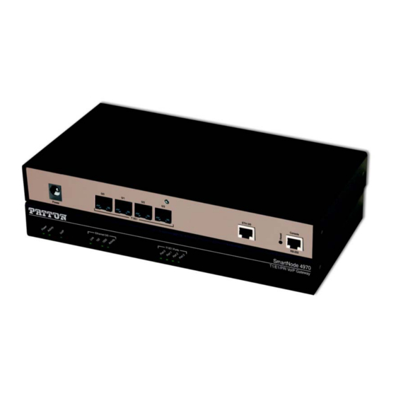
SmartNode 4970A User Manual 1 • General information SmartNode 4970A front panel Figure 3 shows SmartNode 4970A front panel LEDs, the LED definitions are listed in table 3 on page 16. Figure 3. SmartNode 4970A front panel Table 3. SN4970A Front and Rear panel LEDs Description Note If an error occurs, all LEDs will flash once per second. - Page 17 SmartNode 4970A User Manual 1 • General information Table 3. SN4970A Front and Rear panel LEDs (Continued) Description Ethernet Speed 10/ When the Ethernet Link LED is on, then: • On when the Ethernet is connected to a 100Mb network. •...
-
Page 18: Applications Overview
Chapter 2 Applications overview Chapter contents Introduction ................................19 Application—Convert Legacy PBX to VoIP ......................19... -
Page 19: Introduction
Application—Convert Legacy PBX to VoIP The SmartNode 4970A Series can be used to make and receive calls to and from the public ISDN network and Internet Telephony services on any ISDN Terminal (Phone or PBX) (see figure 4). -
Page 20: Smartnode Installation
Chapter 3 SmartNode installation Chapter contents Planning the installation ............................21 Site log ................................21 Network information ............................21 Network Diagram ............................21 IP related information .............................21 Software tools ..............................22 AC Power Mains .............................22 Location and mounting requirements ......................22 Installing the gateway ............................22 Placing the SmartNode ...........................22 Installing cables ...............................22... -
Page 21: Planning The Installation
22 to install the device. Site log Patton recommends that you maintain a site log to record all actions relevant to the system, if you do not already keep such a log. Site log entries should include information such as listed in table 4. -
Page 22: Software Tools
If you suspect that your AC power is not reliable, for example if room lights flicker often or there is machinery with large motors nearby, have a qualified professional test the power. Patton recommends that you include an uninterruptible power supply (UPS) in the installation to ensure that VoIP service is not impaired if the power fails. -
Page 23: Connecting The Pri
SmartNode 4970A User Manual 3 • SmartNode installation Connect the cables in the following order: The interconnecting cables shall be acceptable for external use and shall be rated for the proper application with respect to volt- age, current, anticipated temperature, flammability, and CAUTION mechanical serviceability. -
Page 24: Connecting The Power Supply
3. Verify that the AC power cord included with your router is compatible with local standards. If it is not, refer to chapter 5, “Contacting Patton for assistance” on page 30 to find out how to replace it with a com- patible power cord. -
Page 25: Initial Configuration
Chapter 4 Initial configuration Chapter contents Introduction ................................26 Connecting the SmartNode to Your Laptop PC ....................26 Configure the Desired IP Address ........................27 Factory-default IP Settings ........................27 Login ................................27 Changing the WAN IP address .........................27 Connecting the SmartNode to the Network ....................28 Loading the Configuration (optional)........................29... -
Page 26: Introduction
SmartNode 4970A User Manual 4 • Initial configuration Introduction This chapter leads you through the basic steps to set up a new SmartNode and to download a configuration. Setting up a new SmartNode consists of the following main steps: If you haven’t already installed the SmartNode, refer to Chapter 3, "Smart- Note Node Installation"... -
Page 27: Configure The Desired Ip Address
SmartNode 4970A User Manual 4 • Initial configuration The SmartNode comes with a built-in DHCP client and a fixed IP address to simplify configuration. The SmartNode will receive an IP address from the DHCP server in the network or it can be directly accessed using the static IP address. -
Page 28: Connecting The Smartnode To The Network
SmartNode 4970A User Manual 4 • Initial configuration 192.168.1.1 (cfg) #context ip ROUTER 192.168.1.1 (ctx-ip) [ROUTER} # Now you can set your IP address and network mask for the interface ETH 0/0 (WAN). Within this example a network 172.16.1.0/24 address is assumed. The IP address in this example is set to 172.16.1.99 (you should set the IP address given to you by your network provider). -
Page 29: Loading The Configuration (Optional)
Figure 7. Connecting the SmartNode to the network Loading the Configuration (optional) The Patton Community provides several Web Wizards to help with setting up your SmartNode configuration. http://www.patton.com/wizard Patton also provides a collection of configuration templates on the support page at: http://www.patton.com/support/kb.asp —one of which may be similar enough to your application that you... -
Page 30: Contacting Patton For
Contacting Patton for assistance Chapter contents Introduction ................................31 Contact information..............................31 Patton support headquarters in the USA ......................31 Alternate Patton support for Europe, Middle East, and Africa (EMEA) ............31 Warranty Service and Returned Merchandise Authorizations (RMAs)..............31 Warranty coverage ............................31 Out-of-warranty service ..........................32 Returns for credit ............................32... -
Page 31: Introduction
(RMA). Contact information Patton Electronics offers a wide array of free technical services. If you have questions about any of our other products we recommend you begin your search for answers by using our technical knowledge base. Here, we have gathered together many of the more commonly asked questions and compiled them into a searchable database to help you quickly solve your problems. -
Page 32: Out-Of-Warranty Service
RMA#: xxxx 7622 Rickenbacker Dr. Gaithersburg, MD 20879-4773 USA Patton will ship the equipment back to you in the same manner you ship it to us. Patton will pay the return shipping costs. Warranty Service and Returned Merchandise Authorizations (RMAs) -
Page 33: Compliance Information
Appendix A Compliance information Chapter contents Compliance ................................34 ................................34 Safety ................................34 PSTN Regulatory ............................34 FCC Part 68 (ACTA) Statement ...........................34 Industry Canada Notice ............................35 CE Declaration of Conformity ..........................35 Authorized European Representative ........................35... -
Page 34: Compliance
SmartNode 4970A User Manual A • Compliance information Compliance • EN55022, Class A • EN55024 Safety • IEC/EN62368-1 PSTN Regulatory • ACTA (Part 68) • IC CS-03 • AS/ACIF S016:2001 • AS/ACIF S038:2001 • ETSI TBR 12, TBR 12/A1 & TBR 13 •... -
Page 35: Industry Canada Notice
SmartNode 4970A User Manual A • Compliance information Industry Canada Notice This equipment meets the applicable Industry Canada Terminal Equipment Technical Specifications. This is confirmed by the registration number. The abbreviation, IC, before the registration number signifies that regis- tration was performed based on a Declaration of Conformity indicating that Industry Canada technical speci- fications were met. -
Page 36: Specifications
Appendix B Specifications Chapter contents Voice connectivity ..............................37 Data connectivity ..............................37 Voice processing (signaling dependent) .........................37 Fax and modem support............................37 Voice signaling ..............................38 Voice routing—session router..........................38 IP services ................................38 Management .................................39 System ...................................39 Physical .................................39... -
Page 37: Voice Connectivity
SmartNode 4970A User Manual B • Specifications Refer to the software feature matrix for the most up-to-date specifications. Note Voice connectivity 4 PRI T1/E1 ports on RJ48C connectors (1 port PRI T1/E1 - See SN4170 series) Net/User configurable per port Each port can be slave or master clock Each port can be used to synchronize to an external clock master Failover relay between ports 0/0–0/1 and 0/2–0/3 for specific models (/R in SKU code) -
Page 38: Voice Signaling
SmartNode 4970A User Manual B • Specifications Voice signaling SIPv2, SIPv2 over IPv6 SIPv2 over TLS (separate license required - additional charge) SIP call transfer, redirect Overlap or en-bloc dialing DTMF in-band, out-of-band Configurable progress tones Voice routing—session router Local switching (hairpinning) Least cost routing Interface huntgroups Call-Distribution groups... -
Page 39: Management
SmartNode 4970A User Manual B • Specifications OpenVPN, L2TP, IPSec (License at additional charge) ICMP redirect (RFC 792); Packet fragmentation DiffServe/ToS set or queue per header bits Packet Policing discards excess traffic DHCP client and server (IPv4 and IPv6—Dual Stack) DNS client and relay-server, DynDNS Management Web-based GUI;... - Page 40 Appendix C Cabling Chapter contents Introduction ................................41 Console .................................41 Ethernet ................................42 E1 PRI ..................................43 T1 PRI ..................................44...
-
Page 41: C Cabling
0 /0 0 /1 o le Serial Terminal Note A Patton Model 16F-561 RJ45 to DB-9 adapter is included with each SmartNode 4970 Series device Figure 8. Connecting a serial terminal See section “Console port” on page 47 for console port pin-outs. -
Page 42: Ethernet
SmartNode 4970A User Manual C • Cabling Ethernet Ethernet devices (10Base-T/100Base-T/1000Base-T) are connected to the SmartNode over a cable with RJ-45 plugs. The Ethernet port on the SN4970A is Auto-MDX and uses any straight or crossover cable to connect to hubs, switches, PCs or other devices. -
Page 43: E1 Pri
SmartNode 4970A User Manual C • Cabling RJ-45, male RJ-45, male Figure 10. Typical Ethernet straight-through cable diagram for 1000Base-T E1 PRI The E1 PRI is usually connected to a PBX or switch—local exchange (LE). Type and pin outs of these devices vary depending on the manufacturer. -
Page 44: T1 Pri
SmartNode 4970A User Manual C • Cabling RJ-48C, male RJ-48C, male RX Ring RX Ring RX Tip RX Tip RX Shield RX Shield TX Ring TX Ring TX Tip TX Tip TX Shield TX Shield *N/C = No connection* Figure 12. E1 PRI port crossover cable T1 PRI The T1 PRI is usually connected to a PBX or switch—local exchange (LE). -
Page 45: T1 Pri Crossover Cable
SmartNode 4970A User Manual C • Cabling RJ-45, male RJ-45, male RX Ring RX Ring RX Tip RX Tip RX Shield RX Shield TX Ring TX Ring TX Tip TX Tip TX Shield TX Shield *N/C = No connection* Figure 14. T1 PRI crossover cable T1 PRI... - Page 46 Appendix D Port pin-outs Chapter contents Introduction ................................47 Console port................................47 Ethernet ................................47 PRI port ................................48...
-
Page 47: D Port Pin-Outs
SmartNode 4970A User Manual D • Port pin-outs Introduction This section provides pin-out information for the ports of the SmartNode. Console port Configuration settings: 9600 bps, 8 bits, no parity, 1 stop bit, no flow control. 8–RTS (N/C) 7–CTS (N/C) 6–TD 5–RD 4–SG... -
Page 48: Pri Port
SmartNode 4970A User Manual D • Port pin-outs Table 7. Ethernet: RJ45 socket 1000Base-T (Continued) Signal TRD3+ TRD3- PRI port Table 8. PRI: RJ-45 socket RX Ring RX Tip RX Shield TX Ring TX Tip TX Shield Pins not listed are not used. Note PRI port... -
Page 49: E Smartnode 4970A Factory Configuration
Appendix E SmartNode 4970A factory configuration Chapter contents Introduction ................................50... -
Page 50: Introduction
SmartNode 4970A User Manual E • SmartNode 4970A factory configuration Introduction Factory configuration settings for the SmartNode device can be obtained with the following command through the CLI; login: admin password: <Enter> 192.168.1.1>show config:shipping-config See Chapter 4, "Initial configuration" on page 25 for more details about IP address settings for initial configu- ration. -
Page 51: F Reset Button Functions
Appendix F Reset Button Functions Chapter contents Introduction ................................52 Resetting the SmartNode device when it is operating and the Power LED is lit .............52 Resetting the SmartNode device when it is initially powered off ................53... -
Page 52: Introduction
SmartNode 4970A User Manual F • Reset Button Functions Introduction The Reset button (see figure 16 on page 52) is used to do the following: • Reboot the SmartNode device (see section “Resetting the SmartNode device when it is operating and the Power LED is lit”... -
Page 53: Resetting The Smartnode Device When It Is Initially Powered Off
This procedure should only be performed if the SmartNode device is not booting properly. It should used by trained Smart- Node technicians and Patton Support personnel only. CAUTION If the SmartNode device is not booting properly, the Reset button may remedy the problem as follows: •... -
Page 54: G End User License Agreement
Appendix G End user license agreement Chapter contents End User License Agreement ..........................55 1. Definitions ..............................55 2. Title ................................55 3. Term ................................55 4. Grant of License ............................55 5. Warranty ..............................56 6. Termination ..............................56 7. Notices ...............................56 8. Other Licenses ............................56 9. -
Page 55: End User License Agreement
End User agrees to the following conditions: 1. Definitions “Effective Date” shall mean the earliest date of purchase or download of a product containing the Patton Electronics Company Program(s) or the Program(s) themselves. “Program(s)” shall mean all software, software documentation, source code, object code, or executable code. -
Page 56: Warranty
Program(s), even if Patton Electronics Company has been advised of the possi- bility of such damages. Because some states do not allow the exclusion or limitation of liability for consequen- tial or incidental damages, the above limitation may not apply to you. -
Page 57: Unenforceable Provisions
State of Maryland, USA for any dispute arising under or relating to this agreement and waives user’s right to institute legal proceedings in any other jurisdiction. Patton shall be entitled to institute legal proceedings in connection with any matter arising under this agreement in any juris- diction where User resides, does business, or has assets.
Need help?
Do you have a question about the SmartNode 4970A Series and is the answer not in the manual?
Questions and answers