Table of Contents
Advertisement
Quick Links
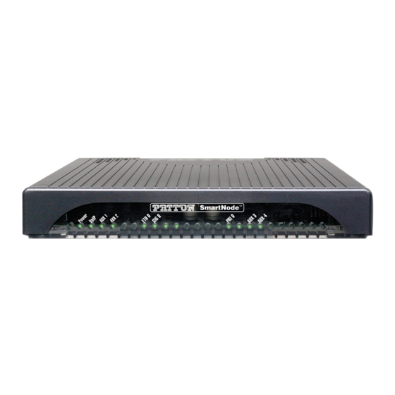
SmartNode SN4170
E1/T1 PRI VoIP Gateway
User Manual
This is a Class A device and is not intended for use in a residential environment.
Sales Office:
+1 (301) 975-1000
Technical Support:
+1 (301) 975-1007
E-mail:
support@patton.com
WWW:
www.patton.com
Part Number: 07MSN4170-GS, Rev. C
Revised: July 30, 2018
:
Advertisement
Chapters
Table of Contents

Related Manuals for Patton SmartNode SN4170


Summary of Contents for Patton SmartNode SN4170
- Page 1 SmartNode SN4170 E1/T1 PRI VoIP Gateway User Manual This is a Class A device and is not intended for use in a residential environment. Sales Office: +1 (301) 975-1000 Technical Support: +1 (301) 975-1007 E-mail: support@patton.com WWW: www.patton.com Part Number: 07MSN4170-GS, Rev. C...
- Page 2 Copyright © 2015–2018, Patton Electronics Company. All rights reserved. The information in this document is subject to change without notice. Patton Elec- tronics assumes no liability for errors that may appear in this document.
-
Page 3: Summary Table Of Contents
Port pin-outs SmartNode SN4170 Factory Configuration ..................... .53 . -
Page 4: Table Of Contents
............................14 SmartNode SN4170 Overview ..........................15 SmartNode SN4170 Rear Panel ........................15 SmartNode SN4170 Front Panel ........................18... - Page 5 ........................36 Contacting Patton for Assistance Introduction ................................37 Contact information..............................37 Contacting Patton Technical Services for Free Support ...................37 Warranty Service and Returned Merchandise Authorizations (RMAs)..............37 Warranty coverage ............................37 RMA numbers ..............................38...
- Page 6 SmartNode 4170 User Manual Table of Contents Introduction ................................56 Resetting the SmartNode device when it is operating and the Power LED is lit.............56 Resetting the SmartNode device when it is initially powered off ................57 End User License Agreement ..........................58 End User License Agreement ..........................59 1.
-
Page 7: List Of Figures
SmartNode SN4170 rear panel ports (SN4170/2ETH model shown) ....... 16... -
Page 8: List Of Tables
SmartNode SN4170 LED Definitions ........ -
Page 9: About This Guide
About this guide This guide describes the SmartNode SN4170 hardware, installation and basic configuration. For detailed soft- ware configuration information refer to the Trinity Command Line Reference Guide and the available Web Wiz- ard. Audience This guide is intended for the following users: Operators •... -
Page 10: Safety When Working With Electricity
CAUTION Safety when working with electricity The SmartNode device contains no user serviceable parts, and is not be opened by the user. The equipment shall be returned to Patton Electronics for repairs or repaired by qualified service personnel. WARNING Mains Voltage: In systems without a power switch, line voltages are present in the power supply when the power cord is connected. -
Page 11: Deutsch
SmartNode 4170 User Manual About this guide Hazardous network voltages are present in WAN ports regardless of whether power to the SmartNode is ON or OFF. To avoid electric shock, use caution when near WAN ports. When detaching the cables, detach the end away from the Smart- WARNING Node first. -
Page 12: General Observations
SmartNode 4170 User Manual About this guide In Übereinstimmung mit den Anforderungen der Richtlinie 2002/96/EG über Elektro- und Elektronik-Altgeräte (WEEE) muss sichergestellt sein, dass Altgeräte von anderem Abfall und Schrott getrennt werden und dem Sammel- und Verwertungssystem für Elektro- und Elektronik-Altgeräte in Ihrem Land zum Recycling zugeführt werden. - Page 13 SmartNode 4170 User Manual About this guide Table 1. General conventions (Continued) Convention Meaning screen Terminal sessions and information the system displays are in screen font. node The leading IP address or nodename of a SmartNode is substituted with node in bold- face italic font.
-
Page 14: General Information
Chapter 1 General Information Chapter contents SmartNode 4170 Overview ...........................15 SmartNode 4170 Rear Panel ...........................15 Ports descriptions ............................16 Rest button functions ..........................17 SmartNode 4170 Front Panel .........................18... -
Page 15: Smartnode Sn4170 Overview
SmartNode SN4170 Rear Panel The SmartNode SN4170 is a compact VoIP Gateway that supports 15 up to 30 VoIP or Fax calls, by using either G.711, G.722, T.38 or any other codec as indicated under Voice Processing in Appendix B, “Specifica-... -
Page 16: Sn4170 Rear Panels
Figure 2. SN4170 Rear Panels Ports descriptions The SmartNode SN4170 rear panel ports (see figure 3) are described in table Figure 3. SmartNode SN4170 rear panel ports (SN4170/2ETH model shown) Table 2. Rear panel ports Port Description ETH 0/0 - ETH 0/1 figure 2... - Page 17 1 stop bit • flow control off 12V DC, 1A figure 2 Electricity supply socket. (see on page 16) Reset The reset button has several functions, as described in appendix F, “Reset Button Functions” on page 55. SmartNode SN4170 Overview...
-
Page 18: Smartnode Sn4170 Front Panel
SmartNode 4170 User Manual 1 • General Information Figure 4. SmartNode SN4170 front panel SmartNode SN4170 Front Panel Figure 4 shows SmartNode SN4170 LEDs, the LED definitions are listed in table Table 3. SmartNode SN4170 LED Definitions Description Note If an error occurs, all LEDs will flash for more than 5 seconds before... -
Page 19: Applications Overview
Chapter 2 Applications Overview Chapter contents Introduction ................................20 Application—Convert Legacy PBX to VoIP ......................20 How it works: ............................20 Application—Migrate from VoIP Gateway to eSBC .....................21 How it works: ............................21... -
Page 20: Introduction
SN4170 VoIP Gateway. Detailed configuration information for SmartNode applications is available Note online at: http://www.patton.com/voip-gateway/. Application—Convert Legacy PBX to VoIP For an installation where there are existing routers and access modems, the SN4170 is a cost-effective solution to bring SIP-trunking service to a traditional PBX. -
Page 21: Application-Migrate From Voip Gateway To Esbc
SmartNode 4170 User Manual 2 • Applications Overview Application—Migrate from VoIP Gateway to eSBC Models containing “SN4171/2ETH” are capable of accepting a software license to achieve this additional func- tionality future proofing your voice network for next generation SIP services and security. Figure 6. -
Page 22: Smartnode
IP related information .............................23 Software tools ..............................24 Power source ..............................24 Location and mounting requirements ......................24 Installing the Patton SmartNode VoIP Gateway....................24 Placing the SmartNode ...........................24 Installing cables ...............................25 Connecting ISDN PBX and NT to the SmartNode’s ISDN PRI port ............25 Connecting the 10/100/1000Base-T Ethernet cable ..................25... -
Page 23: Installation
24 to install the device. Site log Patton recommends that you maintain a site log to record all actions relevant to the system, if you do not already keep such a log. Site log entries should include information such as listed in Table 4. -
Page 24: Software Tools
If you suspect that your AC power is not reliable, for example if room lights flicker often or there is machinery with large motors nearby, have a qualified professional test the power. Patton recommends that you include an uninterruptible power supply (UPS) in the installation to ensure that VoIP service is not impaired if the power fails. -
Page 25: Installing Cables
D, “Port pin-outs” on page Connecting the 10/100/1000Base-T Ethernet cable The SmartNode SN4170 has automatic MDX (auto-cross-over) detection and configuration on the Ethernet port. The port can be connected to a host or hub/switch with a straight-through wired cable. •... -
Page 26: Power Led
2 on page 16). There are no user-serviceable parts in the power supply section of the model SN4170. Contact Patton Electronics Technical Support at support@patton.com for more information CAUTION 2. Verify that the AC power cord included with your device is compatible with local standards. If it is not, refer to “Contacting Patton for Assistance”... -
Page 27: Initial
Chapter 4 Initial Configuration Chapter contents Introduction ................................28 Connecting the SmartNode 4171 to Your Laptop PC ...................28 Configure the Desired IP Address ........................29 Factory-default IP Settings ........................29 Login ................................29 Changing the WAN IP address .........................30 Connecting the SmartNode to the Network ....................30 Connecting SN4171/2ETH models to your PC....................31... -
Page 28: Introduction
POTS line. CAUTION The SmartNode SN4170 is equipped with an Auto-MDX Ethernet port, so you can use straight-through cables for host or hub/switch connections (see figure 8). Introduction... -
Page 29: Configure The Desired Ip Address
SmartNode 4170 User Manual 4 • Initial Configuration Figure 8. Connecting the SmartNode to your Laptop PC The SmartNode comes with a built-in DHCP client and a fixed IP address to simplify configuration. The SmartNode will receive an IP address from the DHCP server in the network or it can be directly accessed using the static IP address. -
Page 30: Connecting The Smartnode To The Network
Connecting the SmartNode to the Network In general, the SmartNode will connect to the network via the WAN (ETH 0/0) port. The SmartNode SN4170 is equipped with an Auto-MDX Ethernet port, so you can use straight through or crossover cables for host or hub/switch connections. -
Page 31: Connecting Sn4171/2Eth Models To Your Pc
SmartNode 4170 User Manual 4 • Initial Configuration For the ISDN connection to a carrier network, it shall be con- nected to a network termination device and not connected directly to an outside POTS line. CAUTION You can check the connection with the ping command from the SmartNode to another host on the network. 172.16.1.99(if-ip)[WAN]#ping <IP Address of the host>... -
Page 32: Configure The Desired Ip Address
SmartNode 4170 User Manual 4 • Initial Configuration Straight-through wired cable LAN (ETH 0/1) Laptop PC Figure 10. Connecting the SmartNode to your Laptop PC The SmartNode comes with a built-in DHCP server to simplify configuration. Therefore, to automatically configure the PC for IP connectivity to the SmartNode, the Laptop PC must be configured for DHCP. The SmartNode will provide the PC with an IP address. -
Page 33: Changing The Wan Ip Address
SmartNode 4170 User Manual 4 • Initial Configuration 192.168.1.1 Accessing your SmartNode via a Telnet session displays the login screen. Type the factory default login: admin and leave the password empty. Press the Enter key after the password prompt. login:admin password: <Enter>... -
Page 34: Loading The Configuration (Optional)
Note enable it. Loading the Configuration (optional) The Patton Community provides several Web Wizards to help with setting up your SmartNode configuration. http://www.patton.com/wizard Patton also provides a collection of configuration templates on the support page at: http://www.patton.com/support/kb.asp —one of which may be similar enough to your application that you... -
Page 35: Additional Information
(remember to modify the IP address) and copy the modified configuration to a TFTP server. The SmartNode can now load its configuration from this server. If your application is unique and not covered by any of Patton’s configura- Note tion templates, you can manually configure the SmartNode instead of load- ing a configuration file template. -
Page 36: Contacting Patton For Assistance
Chapter 5 Contacting Patton for Assistance Chapter contents Introduction ................................37 Contact information..............................37 Contacting Patton Technical Services for Free Support ...................37 Warranty Service and Returned Merchandise Authorizations (RMAs)..............37 Warranty coverage ............................37 Out-of-warranty service ..........................38 Returns for credit ............................38 Return for credit policy ..........................38... -
Page 37: Introduction
(RMA). Contact information Patton Electronics offers a wide array of free technical services. If you have questions about any of our other products we recommend you begin your search for answers by using our technical knowledge base. Here, we have gathered together many of the more commonly asked questions and compiled them into a searchable database to help you quickly solve your problems. -
Page 38: Rma Numbers
RMA#: xxxx 7622 Rickenbacker Dr. Gaithersburg, MD 20879-4773 USA Patton will ship the equipment back to you in the same manner you ship it to us. Patton will pay the return shipping costs. Warranty Service and Returned Merchandise Authorizations (RMAs) -
Page 39: Compliance Information
Appendix A Compliance Information Chapter contents Compliance ................................40 ................................40 Safety ................................40 Radio and TV interference ............................40 CE Declaration of Conformity ..........................40 Authorized European Representative ........................40 ISDN Compliance ..............................41... -
Page 40: Compliance
AC outlet (such that the computing equipment and receiver are on different branches). CE Declaration of Conformity Patton Electronics, Inc declares that this device is in compliance with the essential requirements and other pro- visions of Council Directive 1999/5/EC on the approximation of the laws of the member states relating to Radio and Telecommunication Terminal Equipment and the mutual recognition of their conformity. -
Page 41: Isdn Compliance
SmartNode 4170 User Manual A • Compliance Information ISDN Compliance The device is approved for connection to the public ISDN telecommunication network. For the ISDN connection to a carrier network, it shall be con- nected to a network termination device and not connected directly to an outside POTS line. -
Page 42: Specifications
Appendix B Specifications Chapter contents DSP..................................43 Voice Connectivity ..............................43 Data Connectivity ..............................43 Voice Processing (signalling dependent) ........................43 Fax and modem support............................44 Voice Signalling..............................44 Voice Routing—session gateway..........................44 IP Services ................................45 Management .................................45 System ...................................45 Physical .................................45... -
Page 43: Dsp
SmartNode 4170 User Manual B • Specifications Refer to the software feature matrix for the most up-to-date specifications. Note Two 16 channel DSP Voice Connectivity 1 ISDN PRI port, 4-wire RJ45 port NT/TE configurable per port (layer 1 pin-out does not change) Data Connectivity Two 10/100/1000Base-TX Ethernet ports (SN4171/2ETH) One 10/100/1000Base-TX Ethernet port (SN4171) -
Page 44: Fax And Modem Support
SmartNode 4170 User Manual B • Specifications Fax and modem support Automatic fax and modem detection Codec fallback for modem-bypass T.38 Fax-Relay (Gr. 3 Fax, 9.6 k, 14.4 K) G.711 Fax-Bypass Voice Signalling SIPv2, SIPv2 over TLS SIP call transfer, redirect Overlap or en-bloc dialing DTMF in-band, out-of-band Configurable progress tones... -
Page 45: Ip Services
SmartNode 4170 User Manual B • Specifications IP Services IPv4 gateway; IPv6 basic functionalities Programmable static routes and policy-routing ICMP redirect (RFC 792); Packet fragmentation DiffServe/ToS set or queue per header bits Packet Policing discards excess traffic DHCP client and server DNS client and relay-server, DynDNS Management Web-based GUI;... -
Page 46: Cabling
Appendix C Cabling Chapter contents Introduction ................................47 Serial Console................................47 Ethernet ................................48 ISDN PRI (E1/T1) ...............................49... -
Page 47: Introduction
POTS line. CAUTION o le Serial Terminal Note A Patton Model 16F-561 RJ45 to DB-9 adapter is included with each SmartNode Series device Figure 12. Connecting a serial terminal Console Connection settings: • 19200 Bps •... -
Page 48: Ethernet
SmartNode 4170 User Manual C • Cabling Ethernet Ethernet devices (10/100/1000 Base-T) are connected to the SmartNode over a cable with RJ-45 plugs. The Ethernet port on the SN4170 is Auto-MDX. Use any straight or crossover cable to a host, hubs, switches, PCs or other devices. -
Page 49: Isdn Pri (E1/T1)
SmartNode 4170 User Manual C • Cabling ISDN PRI (E1/T1) The E1/T1 PRI port 0/0 uses the (LE) pinout. In most cases, a straight-through RJ-45 to RJ-45 can be used to connect the device to a PSTN NT. However, pinouts may vary depending on the pinout being used by the NT. If PRI port 0/0 will be connected to a PBX, usually a PRI cross-over cable is required. -
Page 50: Port Pin-Outs
Appendix D Port pin-outs Chapter contents Introduction ................................51 Console port................................51 Ethernet ................................51 ISDN PRI (E1/T1) Port Pin-outs..........................52... -
Page 51: Introduction
SmartNode 4170 User Manual D • Port pin-outs Introduction This section provides pin-out information for the ports of the SmartNode. Console port (N/C) (N/C) (N/C) Pins 1 & 3 are connected together Figure 17. EIA-561 (RJ-45 8-pin) port N/C means no internal electrical connection. Note Console Connection Settings: •... -
Page 52: Isdn Pri (E1/T1) Port Pin-Outs
SmartNode 4170 User Manual D • Port pin-outs Table 8. 1000Base-T RJ-45 Socket Signal TRD0+ TRD0- TRD1+ TRD1- TRD2+ TRD2- TRD3+ TRD3- ISDN PRI (E1/T1) Port Pin-outs Table 9. Port 0/0 Signal RX_TIP RX_RING TX_TIP TX_RING Pins not listed are not used Note ISDN PRI (E1/T1) Port Pin-outs... -
Page 53: E Smartnode Sn4170 Factory Configuration
Appendix E SmartNode SN4170 Factory Configuration Chapter contents Introduction ................................54... -
Page 54: Introduction
SmartNode 4170 User Manual E • SmartNode SN4170 Factory Configuration Introduction The factory configuration settings for SmartNode SN4170 can be obtained with the following command through the CLI; login: admin password: <Enter> 192.168.1.1>show config:shipping-config Please see Chapter 4, "Initial Configuration"... -
Page 55: F Reset Button Functions
Appendix F Reset Button Functions Chapter contents Introduction ................................56 Resetting the SmartNode device when it is operating and the Power LED is lit .............56 Resetting the SmartNode device when it is initially powered off ................57... -
Page 56: Introduction
SmartNode 4170 User Manual F • Reset Button Functions Introduction The Reset button (see figure 18) is used to do the following: • Reboot the SmartNode device (see section “Resetting the SmartNode device when it is operating and the Power LED is lit”) •... -
Page 57: Resetting The Smartnode Device When It Is Initially Powered Off
This procedure should only be performed if the SmartNode device is not booting properly. It should used by trained Smart- Node technicians and Patton Support personnel only. CAUTION If the SmartNode device is not booting properly, the Reset button may remedy the problem as follows: •... -
Page 58: G End User License Agreement
Appendix G End User License Agreement Chapter contents End User License Agreement ..........................59 1. Definitions ..............................59 2. Title ................................59 3. Term ................................59 4. Grant of License ............................59 5. Warranty ..............................60 6. Termination ..............................60 7. Notices ...............................60 8. Other Licenses ............................60 9. -
Page 59: End User License Agreement
End User agrees to the following conditions: 1. Definitions “Effective Date” shall mean the earliest date of purchase or download of a product containing the Patton Electronics Company Program(s) or the Program(s) themselves. “Program(s)” shall mean all software, software documentation, source code, object code, or executable code. -
Page 60: Warranty
Program(s), even if Patton Electronics Company has been advised of the possi- bility of such damages. Because some states do not allow the exclusion or limitation of liability for consequen- tial or incidental damages, the above limitation may not apply to you. -
Page 61: Unenforceable Provisions
State of Maryland, USA for any dispute arising under or relating to this agreement and waives user’s right to institute legal proceedings in any other jurisdiction. Patton shall be entitled to institute legal proceedings in connection with any matter arising under this agreement in any juris- diction where User resides, does business, or has assets.
Need help?
Do you have a question about the SmartNode SN4170 and is the answer not in the manual?
Questions and answers