Table of Contents
Advertisement
Quick Links
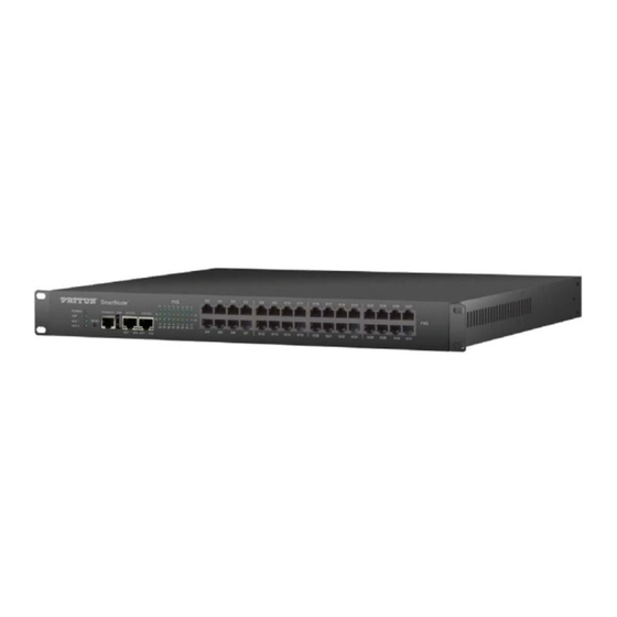
SmartNode 4740 Series
16–32 Port Analog High Density
Gateway
User Manual
This is a Class A device and is not intended for use in a residential environment.
REGULATORY MODEL NUMBER: 13269D4-001
Sales Office:
+1 (301) 975-1000
Technical Support:
+1 (301) 975-1007
E-mail:
support@patton.com
WWW:
www.patton.com
Part Number: 50000065, Rev. C
Revised: July 9, 2020
Advertisement
Table of Contents

Related Manuals for Patton SmartNode 4740 Series


Summary of Contents for Patton SmartNode 4740 Series
- Page 1 SmartNode 4740 Series 16–32 Port Analog High Density Gateway User Manual This is a Class A device and is not intended for use in a residential environment. REGULATORY MODEL NUMBER: 13269D4-001 Sales Office: +1 (301) 975-1000 Technical Support: +1 (301) 975-1007 E-mail: support@patton.com...
- Page 2 Copyright © 2020, Patton Electronics Company. All rights reserved. The information in this document is subject to change without notice. Patton Electronics assumes no liability for errors that may appear in this document. Warranty Information The software described in this document is furnished under a license and may be used or copied only in accordance with the terms of such license.
-
Page 3: Summary Table Of Contents
Port pin-outs SmartNode 4740 Series Factory Configuration ....................60 . -
Page 4: Table Of Contents
SmartNode 4740 Series Overview .........................19 Applications ................................20 SmartNode 4740 Series Rear Panel .........................22 SmartNode 4740 Series Front Panel .......................23 Installation............................27... - Page 5 SmartNode 4740 Series (16–32 Ports) User Manual Table of Contents Changing the WAN IP address (Optional) .....................36 Connecting the SmartNode to the Network ......................36 Loading the Configuration (optional)........................37 Additional Information ............................38 Contacting Patton for Assistance ........................39 Introduction ................................40...
- Page 6 SmartNode 4740 Series (16–32 Ports) User Manual Table of Contents ....................60...
-
Page 7: List Of Figures
SmartNode 4740 Series front panel (RJ11 version) ........ -
Page 8: List Of Tables
List of Tables General conventions ..............12 SN4740 Series rear panel descriptions . -
Page 9: About This Guide
About this guide This guide describes the SmartNode 4740 Series Analog High Density Gateway (16 to 32 ports) hardware, installation and basic configuration. For detailed software configuration information refer to the Trinity Soft- ware Configuration Guide and the available Knowledgebase, as well as the Wizard portal. -
Page 10: Safety When Working With Electricity
CAUTION Safety when working with electricity The SmartNode device contains no user serviceable parts, and is not be opened by the user. The equipment shall be returned to Patton Electronics for repairs or repaired by qualified service personnel. WARNING Mains Voltage: In systems without a power switch, line voltages are present in the power supply when the power cord is connected. -
Page 11: Deutsch
SmartNode 4740 Series (16–32 Ports) User Manual Hazardous network voltages are present in WAN ports regardless of whether power to the SmartNode is ON or OFF. To avoid electric shock, use caution when near WAN ports. When detaching the cables, detach the end away from the Smart- WARNING Node first. -
Page 12: General Observations
SmartNode 4740 Series (16–32 Ports) User Manual In Übereinstimmung mit den Anforderungen der Richtlinie 2002/96/EG über Elektro- und Elektronik-Altgeräte (WEEE) muss sichergestellt sein, dass Altgeräte von anderem Abfall und Schrott getrennt werden und dem Sammel- und Verwertungssystem für Elektro- und Elektronik-Altgeräte in Ihrem Land zum Recycling zugeführt werden. - Page 13 SmartNode 4740 Series (16–32 Ports) User Manual Table 1. General conventions (Continued) Convention Meaning The leading SN on a command line represents the nodename of the SmartNode An hash sign at the beginning of a line indicates a comment line.
-
Page 14: Quick
Chapter 1 Quick Start Chapter contents Default IP Settings ..............................15 ETH 0/0 .................................15 ETH 0/1 .................................15 Default Login ................................15 Analog Port Pinout..............................16 Console port................................17... -
Page 15: Default Ip Settings
You are responsible for creating a new administrator account to maintain system secu- rity. Patton Electronics accepts no responsibility for losses or damage caused by loss or misuse of passwords. Refer to Chapter 4 “Accessing the CLI” , section “Selecting a secure IMPORTANT password”... -
Page 16: Analog Port Pinout
SmartNode 4740 Series (16–32 Ports) User Manual 1 • Quick Start Analog Port Pinout For models with FXS ports terminated on RJ21 connectors, see the detailed pin-out in Appendix D, section “RJ21 Models” on page 54. Models that come with RJ11 ports use a 6-position RJ11 connector. The middle 2 positions (3 and 4) are used as follows: Pins not listed are not used. -
Page 17: Console Port
SmartNode 4740 Series (16–32 Ports) User Manual 1 • Quick Start Console port (N/C) (N/C) (N/C) Pins 1 & 3 are connected together Figure 2. EIA-561 (RJ-45 8-pin) port N/C means no internal electrical connection. Note Console Connection Settings: 19200bps •... -
Page 18: General Information
Chapter 2 General Information Chapter contents SmartNode 4740 Series Overview .........................19 Applications ................................20 SmartNode 4740 Series Rear Panel .........................22 SmartNode 4740 Series Front Panel .......................23... -
Page 19: Smartnode 4740 Series Overview
2 • General Information SmartNode 4740 Series Overview The SmartNode 4740 Series are analog high density VoIP gateways that are available in 16, 24, and 32-tele- phony port versions. The SN4740 is equipped with RJ11 or RJ21 50-pin FXS telco connectors. (see... -
Page 20: Applications
SmartNode 4740 Series (16–32 Ports) User Manual 2 • General Information Figure 4. SN4740 front panel (RJ21 version) Users for the SN4740 Series include: • Carriers/Service providers looking for a way to connect analog telephones of apartment buildings or deliver- ing telephony services by installing the SN4740 in street cabinets (MSAN approach deployment) •... -
Page 21: Hospitality Venues: Hotels, Motels, Etc
SmartNode 4740 Series (16–32 Ports) User Manual 2 • General Information Figure 5. Hospitality venues: hotels, motels, etc. Figure 6. Residential apartments, public administration office, care homes, etc. Figure 7. Factory Campus. Hospital - Emergency Telephones, etc. Applications... -
Page 22: Smartnode 4740 Series Rear Panel
SmartNode 4740 Series (16–32 Ports) User Manual 2 • General Information Figure 8. Mines, tunnels, etc. Figure 9. Train station platform telephones SmartNode 4740 Series Rear Panel The SmartNode 4740 Series rear panel (see on page 23) is described in... -
Page 23: Smartnode 4740 Series Front Panel
Used to secure the device connecting it to Earth Ground. Screw SmartNode 4740 Series Front Panel on page 24 shows the SmartNode 4740 Series front panel with RJ11 telephony ports. Figure 11 Figure 11 page 24 shows the SmartNode 4740 Series front panel with RJ21 telephony ports. -
Page 24: Smartnode 4740 Series Front Panel (Rj11 Version)
SmartNode 4740 Series (16–32 Ports) User Manual 2 • General Information Figure 11. SmartNode 4740 Series front panel (RJ11 version) Applications... -
Page 25: Smartnode 4740 Series Front Panel (Rj21 Version)
SmartNode 4740 Series (16–32 Ports) User Manual 2 • General Information Figure 12. SmartNode 4740 Series front panel (RJ21 version) Table 3. SN4740 Series front panel descriptions Button/LEDs/Ports Description POWER LED When lit, indicates power is applied. Blinks fast during bootloader phase and blinks slow during the boot process. - Page 26 SmartNode 4740 Series (16–32 Ports) User Manual 2 • General Information Table 3. SN4740 Series front panel descriptions Button/LEDs/Ports Description USB 2.0 Port USB 2.0 host port (see figure 11 on page 24 or figure 12) to connect a USB 3G/4G Cellular Modem. A list of supported USB Models can be...
-
Page 27: Smartnode Installation
Chapter 3 SmartNode Installation Chapter contents Planning the Installation............................28 Site log ................................28 Network information ............................28 Network Diagram ............................28 IP related information .............................28 Software tools ..............................29 Power source ..............................29 Location and mounting requirements ......................29 Installing the SmartNode 4740..........................29 Placing the SmartNode device .........................29 Installing cables ...............................30... -
Page 28: Planning The Installation
29 to install the device. Site log Patton recommends that you maintain a site log to record all actions relevant to the system, if you do not already keep such a log. Site log entries should include information such as listed in table Table 4. -
Page 29: Software Tools
If you suspect that your AC power is not reliable, for example if room lights flicker often or there is machinery with large motors nearby, have a qualified professional test the power. Patton recommends that you include an uninterruptible power supply (UPS) in the installation to ensure that VoIP service is not impaired if the power fails. -
Page 30: Installing Cables
Connecting the 10/100/1000Base-T Gigabit Ethernet LAN and WAN cables The SmartNode 4740 Series has automatic MDX (auto-cross-over) detection and configuration on the Ether- net ports. Any of the two ports can be connected to a host or hub/switch with a straight-through wired cable. -
Page 31: Analog Fxs Connection
SmartNode 4740 Series (16–32 Ports) User Manual 3 • SmartNode Installation Installing interface cables on the SmartNode device’s FXS interface ports The SmartNode comes with: • 16, 24 or 32 FXS RJ11 analog ports (see figure 3 on page 19) •... - Page 32 10 on page 23). There are no user-serviceable parts in the power supply section of the model SN4740 Series. Contact Patton Electronics Techni- cal Support at support@patton.com for more information CAUTION 2. Verify that the AC power cord included with your device is compatible with local standards. If it is not, refer to “Contacting Patton for Assistance”...
-
Page 33: Initial
Chapter 4 Initial Configuration Chapter contents Introduction ................................34 Connecting the SmartNode to Your Laptop PC ....................34 Configure the Desired IP Address..........................35 Factory-default IP Settings ..........................35 Login ................................35 Changing the WAN IP address (Optional) .....................36 Connecting the SmartNode to the Network ......................36 Loading the Configuration (optional)........................37... -
Page 34: Introduction
CAUTION mechanical serviceability. The SmartNode 4740 Series is equipped with Auto-MDX Ethernet ports, so you can use straight-through cables for host or hub/switch connections (see figure 14). -
Page 35: Configure The Desired Ip Address
You are responsible for creating a new administrator account to maintain system secu- rity. Patton Electronics accepts no responsibility for losses or damage caused by loss or misuse of passwords. Refer to Chapter 4 “Accessing the CLI” , section “Selecting a secure IMPORTANT password”... -
Page 36: Changing The Wan Ip Address (Optional)
Node to offer routing services to the PC hosts on LAN (ETH 0/1) port (IP Routing License Required at addi- tional cost). The SmartNode 4740 Series is equipped with Auto-MDX Ethernet ports, so you can use straight through or crossover cables for host or hub/switch connections. (See figure 15 on page 37). -
Page 37: Loading The Configuration (Optional)
Loading the Configuration (optional) WebWizard Community provides a collection of Wizards that help to reduce the setup time of a Patton device. Simply download the Wizard to your device, execute it locally, and you are ready to do phone calls after the SmartNode has rebooted. -
Page 38: Additional Information
Press 'yes' to restart, 'no' to cancel : yes The system is going down NOW Additional Information For detailed information about configuring and operating guidance, set up procedures, and troubleshooting, refer to the Trinity Software Configuration Guide available online at www.patton.com/manuals. Additional Information... -
Page 39: Contacting Patton For Assistance
Chapter 5 Contacting Patton for Assistance Chapter contents Introduction ................................40 Contact information..............................40 Contacting Patton Technical Services for Free Support ...................40 Warranty Service and Returned Merchandise Authorizations (RMAs)..............40 Warranty coverage ............................40 Out-of-warranty service ..........................41 Returns for credit ............................41 Return for credit policy ..........................41... -
Page 40: Introduction
(RMA). Contact information Patton Electronics offers a wide array of free technical services. If you have questions about any of our other products we recommend you begin your search for answers by using our technical knowledge base. Here, we have gathered together many of the more commonly asked questions and compiled them into a searchable database to help you quickly solve your problems. -
Page 41: Rma Numbers
RMA#: xxxx 7622 Rickenbacker Dr. Gaithersburg, MD 20879-4773 USA Patton will ship the equipment back to you in the same manner you ship it to us. Patton will pay the return shipping costs. Warranty Service and Returned Merchandise Authorizations (RMAs) -
Page 42: A Compliance Information
Appendix A Compliance Information Chapter contents Compliance ................................43 ................................43 Safety ................................43 Radio and TV Interference (FCC Part 15) ......................43 EC Declaration of Conformity ..........................43 Authorized European Representative ........................43... -
Page 43: Compliance
SmartNode 4740 Series (16–32 Ports) User Manual A • Compliance Information Compliance • FCC Part 15, Class A • EN55032, Class A • EN55024 Safety • UL 62368-1/CSA C22.2 N0. 62368-1 • IEC/62368-1 Radio and TV Interference (FCC Part 15) This equipment generates and uses radio frequency energy, and if not installed and used properly—that is, in... -
Page 44: Specifications
Appendix B Specifications Chapter contents Capacity ................................45 SIP Signaling .................................45 Voice Processing..............................45 Call Switching & Services............................45 FXS Connectivity ..............................46 FXO Connectivity (coming soon) .........................46 Connectivity................................46 Quality of Service, SLA Assurance .........................47 Management .................................47 Power ..................................47 Dimensions & Packaging ............................47 Environment .................................48 Safety &... -
Page 45: Capacity
SmartNode 4740 Series (16–32 Ports) User Manual B • Specifications Refer to the software feature matrix for the most up-to-date specifications. Note Capacity Up to 32 simultaneous low bandwidth voice or HD calls with SRTP** or T.38 fax calls SIP Signaling •... -
Page 46: Fxs Connectivity
SmartNode 4740 Series (16–32 Ports) User Manual B • Specifications • Digit collection, call distribution and hunt groups • Transparent line extension • Fallback Routing: Soft fallback to alternative route(s) FXS Connectivity • 2-wire Loopstart on RJ-11 or RJ21 (Telco 50-pin) •... -
Page 47: Quality Of Service, Sla Assurance
SmartNode 4740 Series (16–32 Ports) User Manual B • Specifications • ICMP • Dynamic and static NAT and NAPT • Intelligent ACL • DNS, DynDNS • STP Client Quality of Service, SLA Assurance • Patton Cloud based Call Quality Monitoring & Alerting** •... -
Page 48: Environment
Specifications subject to change without notice | Product images shown may not be an exact representation of the actual product | * Depending on model | ** Licensed Feature at additional charge Patton Cloud based features & services depend on Cloud Service plans which are to be purchased separately Environment... -
Page 49: Cabling
Appendix C Cabling Chapter contents Introduction ................................50 Ethernet ................................50 Analog FXS ................................51... -
Page 50: Introduction
SmartNode 4740 Series (16–32 Ports) User Manual C • Cabling Introduction This section provides information on the cables used to connect the SmartNode to the existing network infra- structure and to third party products. Ethernet Ethernet devices (10/100/1000 Base-T) are connected to the SmartNode over a cable with RJ-45 plugs. All Ethernet ports on the SN4740 Series are Auto-MDX. -
Page 51: Analog Fxs
SmartNode 4740 Series (16–32 Ports) User Manual C • Cabling Analog FXS The Interconnecting cables shall be acceptable for external use and shall be rated for the proper application with respect to volt- age, current, anticipated temperature, flammability, and CAUTION mechanical serviceability. - Page 52 Appendix D Port pin-outs Chapter contents Introduction ................................53 Ethernet ................................53 port................................53 RJ11 Models ..............................53 RJ21 Models ..............................54 Pin-outs for 16 and 24-Port Models ......................54 Pin-outs for 32-Port Devices ........................57...
-
Page 53: D Port Pin-Outs
SmartNode 4740 Series (16–32 Ports) User Manual D • Port pin-outs Introduction This section provides pin-out information for the ports of the SmartNode. Ethernet Table 7. 10/100Base-T RJ-45 socket Signal Pins not listed are not used. Note Table 8. 1000Base-T RJ-45 Socket... -
Page 54: Rj21 Models
SmartNode 4740 Series (16–32 Ports) User Manual D • Port pin-outs Figure 19. RJ-11 pinout diagram RJ21 Models The FXS ports brought out on at least one 50-pin RJ-21 connector (see figure 20) use the following pin-out: • For 16 and 24-port devices, see section “”... -
Page 55: Band Marked Color Code For 16 And 24 Fxs Port Models
SmartNode 4740 Series (16–32 Ports) User Manual D • Port pin-outs Table 10. Band Marked Color Code for 16 and 24 FXS port models Wire/Color Code Tip and Pair 50 Pin SmartNode Ring Number Positions Config-Port Main Color Stripe White... - Page 56 SmartNode 4740 Series (16–32 Ports) User Manual D • Port pin-outs Table 10. Band Marked Color Code for 16 and 24 FXS port models (Continued) Wire/Color Code Tip and Pair 50 Pin SmartNode Ring Number Positions Config-Port Main Color Stripe...
-
Page 57: Band Marked Color Code For Rj21 Connector A (Ports 0/0-0/23)
SmartNode 4740 Series (16–32 Ports) User Manual D • Port pin-outs Pin-outs for 32-Port Devices Connector A (ports 0/0–0/23) (see figure 21 table 11). Figure 21. RJ21 connector 0/0–0/23 Table 11. Band Marked Color Code for RJ21 connector A (ports 0/0–0/23) - Page 58 SmartNode 4740 Series (16–32 Ports) User Manual D • Port pin-outs Table 11. Band Marked Color Code for RJ21 connector A (ports 0/0–0/23) (Continued) Wire/Color Code Tip and Pair 50 Pin SmartNode Ring Number Positions Config-Port Main Color Stripe Black...
-
Page 59: Band Marked Color Code For Rj21 Connector B (Ports 0/24-0/31 )
SmartNode 4740 Series (16–32 Ports) User Manual D • Port pin-outs Connector B (ports 0/24–0/31) (see figure 22 table 12). Figure 22. RJ21 connector 0/24–0/31 Table 12. Band Marked Color Code for RJ21 connector B (ports 0/24–0/31 ) Wire/Color Code... -
Page 60: E Smartnode 4740 Series Factory Configuration
Appendix E SmartNode 4740 Series Factory Configuration Chapter contents Introduction ................................61... -
Page 61: Introduction
SmartNode 4740 Series (16–32 Ports) User Manual E • SmartNode 4740 Series Factory Configuration Introduction The factory configuration settings for SmartNode 4740 Series can be obtained with the following command through the CLI; login: admin password: <Enter> 192.168.1.1>show config:shipping-config Refer to Chapter 4, "Initial Configuration"... -
Page 62: F Reset Button Functions
Appendix F Reset Button Functions Chapter contents Introduction ................................63 Resetting the SmartNode device when it is operating and the POWER LED is lit ..........64 Very exceptional case—minimal config recovery ....................65... -
Page 63: Introduction
SmartNode 4740 Series (16–32 Ports) User Manual F • Reset Button Functions Introduction The RESET button (see figure 23 for the SN4141E) is used to do the following: • Reboot the SmartNode device (see section “Resetting the SmartNode device when it is operating and the POWER LED is lit”... -
Page 64: Resetting The Smartnode Device When It Is Operating And The Power Led Is Lit
SmartNode 4740 Series (16–32 Ports) User Manual F • Reset Button Functions Resetting the SmartNode device when it is operating and the POWER LED is lit The RESET button has the following behaviors depending on how many seconds (see figure... -
Page 65: Very Exceptional Case-Minimal Config Recovery
64, the SmartNode device is still not operational, the following may remedy the problem by erasing the entire contents of flash memory (no exceptions). However it is recommended that in such a case the device be sent to Patton for analysis and repair. See section “Warranty Service and Returned Merchandise Authorizations (RMAs)”... -
Page 66: Using The Reset Button To Switch To A Backup Image
SmartNode 4740 Series (16–32 Ports) User Manual F • Reset Button Functions 2. The POWER LED will begin a series of blink pattern starting with 1-blink, pause. Table 14. Using the Reset button to switch to a backup image LED Blink Pattern... -
Page 67: G End User License Agreement
Appendix G End User License Agreement Chapter contents End User License Agreement ..........................68 1. Definitions ..............................68 2. Title ................................68 3. Term ................................68 4. Grant of License ............................68 5. Warranty ..............................69 6. Termination ..............................69 7. Notices ...............................69 8. Other Licenses ............................69 9. -
Page 68: End User License Agreement
End User agrees to the following conditions: 1. Definitions “Effective Date” shall mean the earliest date of purchase or download of a product containing the Patton Electronics Company Program(s) or the Program(s) themselves. “Program(s)” shall mean all software, software documentation, source code, object code, or executable code. -
Page 69: Warranty
Program(s), even if Patton Electronics Company has been advised of the possi- bility of such damages. Because some states do not allow the exclusion or limitation of liability for consequen- tial or incidental damages, the above limitation may not apply to you. -
Page 70: Unenforceable Provisions
State of Maryland, USA for any dispute arising under or relating to this agreement and waives user’s right to institute legal proceedings in any other jurisdiction. Patton shall be entitled to institute legal proceedings in connection with any matter arising under this agreement in any juris- diction where User resides, does business, or has assets.
Need help?
Do you have a question about the SmartNode 4740 Series and is the answer not in the manual?
Questions and answers