Sign In
Upload
Manuals
Brands
Patton Manuals
Gateway
SmartNode 2300
Patton SmartNode 2300 Manuals
Manuals and User Guides for Patton SmartNode 2300. We have
1
Patton SmartNode 2300 manual available for free PDF download: Getting Started Manual
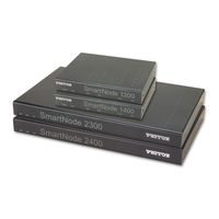
Patton SmartNode 2300 Getting Started Manual (181 pages)
SmartNode 1000 & 2000 Series VoIP Media Gateways
Brand:
Patton
| Category:
Gateway
| Size: 7.12 MB
Table of Contents
Table of Contents
3
Contents
3
Compliance
9
Emc
9
PSTN Regulatory (SN1200 & SN1400)
9
Safety
9
FCC Part 68 (ACTA) Statement (SN2300 & SN2400 with T1V Card)
10
Industry Canada Notice (SN2300 & SN2400 with T1V Card)
10
Service
11
Compliance Information
9
Radio and TV Interference (FCC Part 15)
9
Declaration of Conformity
9
About this Guide
13
Audience
13
How to Read this Guide
13
Precautions
14
Safety When Working with Electricity
15
General Observations
16
Preventing Electrostatic Discharge Damage
16
Structure
14
Typographical Conventions Used in this Document
17
General Conventions
17
Mouse Conventions
17
General Information
19
Chapter 1 General Information
21
Introduction
21
Smartnode 1200 Description
22
Front Panel
22
Rear Panel
23
Clock Mode Configuration (Model SN1200)
25
Smartnode 1400 Description
25
Front Panel
25
Rear Panel
26
Clock Mode Configuration (Model SN1400)
27
Smartnode 2300 Description
28
Front Panel
29
Rear Panel
29
Expansion Slots
30
On-Board Ports
30
Smartnode 2400 Description
32
Front Panel
32
Rear Panel
33
Expansion Slots
33
On-Board Ports
33
Interface Cards Descriptions
35
IC-4FXS Gateway Interface Card for 4 Analog FXS Ports
35
Front Panel
35
Description
36
Ports
36
IC-4BRV 8-Channel Gateway Interface Card for ISDN BRI
37
Front Panel
37
Ports
37
Description
38
Hardware Bypass
38
Operating Modes
38
Network Integration
39
Line Power Jumper Settings
41
S-Bus Line Power
41
Jumper Settings for IC-4BRV and PM-48V-INT (or PM-40V-INT)
42
IC-4BRV-8V 8-Channel Gateway Interface Card for ISDN BRI
43
Description
44
Front Panel
44
Ports
44
Line Power Jumper Settings
45
Operating Modes
45
S-Bus Line Power
45
IC-4BRV-8VR-8-Channel Gateway Interface Card for ISDN BRI with Hardware Bypass (Emergency) Relay
46
IC-E1V 30-Channel E1 Gateway Interface Card for ISDN PRI
47
Description
47
Front Panel
47
Interface
47
Interface Modes
48
IC-E1V-0 E1 Gateway Interface Card for ISDN PRI (Circuit Switching Only)
48
IC-E1V-15 15-Channel E1 Gateway Interface Card for ISDN PRI
48
IC-T1V 23-Channel T1 Gateway Interface Card for ISDN PRI
48
Description
49
Front Panel
49
Interface
49
Interface Modes
50
IC-T1V-0 T1 Gateway Interface Card for ISDN PRI (Circuit Switching Only)
50
IC-T1V-15 15-Channel T1 Gateway Interface Card for ISDN PRI
50
General Information
45
Jumper Settings for IC-4BRV-8V
46
Product Overview
51
Chapter 2 Product Overview
53
Introduction
53
System Model of the Smartnode 1000 and 2000 Series
54
Voice Routing
54
Smartnode Deployment
55
Customer Premises Gateway; Multi-Service Providers
55
Small Office or Home Office (SOHO)
55
Small and Medium Enterprise (SME)
56
Multi-Service Gateway/Router for Private Enterprise Networks
58
Company Branch Office
58
Company Headquarters
59
IP Access to the WAN
59
ISDN Gateway; LAN-Based PBX or Call Center Applications
60
LAN-Based Telephony Gateways (GW)
60
Planning the Installation
61
Chapter 3 Planning the Installation
63
Introduction
63
Installation Checklist
64
Site Log
64
Network Information
65
Network Diagram
65
IP Related Information
65
ISDN Related Information
65
S-Bus Installation
65
Installing an S-Bus Power Supply
66
Smartnode BRI Port Configured in NET Mode
66
Smartnode BRI Port Configured in USR Mode and Connected to an S-Bus
66
Synchronous Serial Interface
66
Software Tools
67
Power Source
67
Where to Go Next
67
Smartnode 1200 Installation
69
Chapter 4 Smartnode 1200 Installation
71
Hardware Installation
71
Mounting the Smartnode 1200
71
Desktop Installation
71
Wall-Mounted Installation
72
Connecting Cables
73
Installing the Ethernet Cables
73
Installing the BRI Cables
74
External S-Bus Power Supply
76
Installing the Power Cord
79
Smartnode 1400 Installation
81
Chapter 5 Smartnode 1400 Installation
83
Hardware Installation
83
Mounting the Smartnode 1400
83
Desktop Installation
83
Wall-Mounted Installation
84
Connecting Cables
85
Installing the Ethernet Cables
85
Installing the BRI Cables
86
External S-Bus Power Supply
88
Installing the Power Cord
90
Smartnode 2300 Installation
91
Chapter 6 Smartnode 2300 Installation
93
Hardware Installation
93
Mounting the Smartnode 2300
93
Desktop Installation
94
Rack-Mounted Installation
94
Connecting Cables
96
Installing the Ethernet Cables
97
Installing the Serial Interface Cable
98
Installing the Interface Card Cables
101
Installing the IC-4FXS Interface Card Cables
101
Installing the IC-4BRV-8V Interface Card Cables
102
Installing the IC-E1V Interface Card Cables
105
Installing the IC-T1V Interface Card Cables
106
Installing the Power Cord
107
Smartnode 2400 Installation
109
Chapter 7 Smartnode 2400 Installation
111
Hardware Installation
111
Mounting the Smartnode 2400
111
Desktop Installation
112
Rack-Mounted Installation
112
Connecting Cables
114
Installing the Ethernet Cables
115
Installing the Interface Card Cables
116
Installing the IC-4FXS Interface Card Cables
117
Installing the IC-4BRV-8V Interface Card Cables
118
Installing the IC-E1V Interface Card Cables
120
Installing the IC-T1V Interface Card Cables
121
Installing the Power Cord
123
Line Power Module Installation
125
Chapter 8 Line Power Module Installation
127
Introduction
127
Safety Recommendation
127
Internal PM-48V-INT or PM-40V-INT Line Power Module Installation
127
Smartnode 2300 Line Power Module Installation
128
Smartnode 2400 Line Power Module Installation
130
Completing the Installation
131
External S-Bus Power Supply
132
Interface Card Installation
133
Chapter 9 Interface Card Installation
135
Introduction
135
Safety Recommendation
135
Installing Interface Cards
136
Card Locating Screws
137
Getting Started with the Smartnode Device
139
Chapter 10 Getting Started with the
141
Introduction
141
Configure IP Address
142
Power Connection and Default Configuration
142
Connect with the Serial Interface
142
Login
143
Changing the IP Address
143
Connect the Smartnode to the Network
144
Load Configuration
145
Bootloader
145
Start Bootloader and Login
145
Main Shell and Domains
146
Route Table Manager (RTM)
147
Download Agent
148
Diagnostic
150
Additional Information
150
Monitoring Status
151
Status Leds
153
Contacting Patton for Assistance
155
Introduction
157
Contact Information
157
Patton Support Headquarters in the USA
157
Alternate Patton Support for Europe, Middle East, and Africa (EMEA)
157
Warranty Service and Returned Merchandise Authorizations (Rmas)
157
Warranty Coverage
157
Out-Of-Warranty Service
158
Return for Credit Policy
158
Returns for Credit
158
RMA Numbers
158
Shipping Instructions
158
A Specifications
160
Appendix A Specifications
161
Physical Description
161
Sn1200
161
Sn1400
161
Sn2300
161
Sn2400
161
IC-4Brv-8V
162
IC-E1V
162
IC-4Fxs
162
Line Power Module
162
T1/E1 Daughter Card Hardware Interface (Software Selectable)
163
Indication Leds
163
Identification of the Smartnode Devices Via SNMP
163
B Cabling
166
Appendix B Cabling
167
Introduction
167
Serial Console
167
Ethernet 10Base-T and 100Base-T
168
And X.21
169
Bri
171
E1 Pri
173
T1 Pri
174
C Port Pin-Outs
178
Introduction
179
Console Port
179
Ethernet 10Base-T and 100Base-T Port
179
BRI Port
179
FXS Port
180
PRI Port
180
Serial Port
181
Advertisement
Advertisement
Related Products
Patton SmartNode 2000 Series
Patton SN4112S
Patton SmartNode SN4170
Patton SmartNode SN10100A Series
Patton SmartNode SN4940/1E24V/EUI
Patton SN4970/4E24VR/EUI
Patton SN4970/4E96VR/EUI
Patton SN10100/4E/UI
Patton SN10100/8E/UI
Patton SN10100/8E/R48
Patton Categories
Extender
Network Router
Gateway
Grill
Modem
More Patton Manuals
Login
Sign In
OR
Sign in with Facebook
Sign in with Google
Upload manual
Upload from disk
Upload from URL