Table of Contents
Advertisement
For Quick
Start Installation
SmartNode 4300
IpChannel Bank
User Manual
Important
This is a Class A device and is not intended for use in a residential environment.
Sales Office:
+1 (301) 975-1000
Technical Support:
+1 (301) 975-1007
E-mail: support@patton.com
WWW: www.patton.com
Part Number: 07MSN4300, Rev. J
Revised: July 30, 2015
Advertisement
Table of Contents

Related Manuals for Patton SmartNode 4300


Summary of Contents for Patton SmartNode 4300
-
Page 1: User Manual
For Quick Start Installation SmartNode 4300 IpChannel Bank User Manual Important This is a Class A device and is not intended for use in a residential environment. Sales Office: +1 (301) 975-1000 Technical Support: +1 (301) 975-1007 E-mail: support@patton.com WWW: www.patton.com Part Number: 07MSN4300, Rev. - Page 2 Under no condition shall Patton Electronics be liable for any damages incurred by the use of this product. These damages include, but are not limited to, the following: lost profits, lost savings and incidental or consequential damages arising from the use of or inability to use this product.
-
Page 3: Summary Table Of Contents
Summary Table of Contents General Information ............................14 Applications Overview ............................20 Hardware installation............................23 Getting Started with the SmartNode 4300 Series....................34 Contacting Patton for Assistance ........................42 Compliance Information ........................... 45 Specifications ..............................47 Port Pin-outs ..............................53 Factory Configuration ............................ -
Page 4: Table Of Contents
............................13 General conventions General Information ............................14 SmartNode 4300 Series overview...........................15 SmartNode 4300 Series detailed description......................16 ........................17 SmartNode 4300 Series front panel .........................18 SmartNode 4300 Series rear panels ..........................19 Reset button behavior Applications Overview ............................20 ................................21 Introduction SmartNode 4300 Series applications........................21... - Page 5 Connecting power .................30 Grounding the Model SN4300—AC and DC units .......................31 Installing the power cables—AC units ......................32 Installing the power cables—DC units Getting Started with the SmartNode 4300 Series....................34 ................................35 Introduction ............................35 1. Configure IP address ..........................35 Factory-default IP settings .......................35...
- Page 6 SmartNode 4300 Series User Manual Table of Contents ............................48 Voice connectivity - FXO ..............................48 Ethernet interface Console port................................48 ..............................48 FXS/FXO ports ..........................49 PPP and Frame-Relay support .........................49 Voice processing (signaling dependent) Fax and modem support............................49 ..............................50 Voice signaling ..........................50 Voice routing-session router .................................50...
-
Page 7: List Of Figures
SmartNode 4300 rear panels ........ -
Page 8: List Of Tables
List of Tables General conventions ..............13 Front panel LEDs . -
Page 9: About This Guide
About this guide This guide describes the SmartNode 4300 Series IpChannel Bank hardware, installation and basic configura- tion. For detailed software configuration information refer to the SmartWare Software Configuration Guide and the available Configuration Notes. Audience This guide is intended for the following users: •... -
Page 10: Precautions
SmartNode 4300 Series User Manual Precautions Notes, cautions, and warnings, which have the following meanings, are used throughout this guide to help you become aware of potential problems. Warnings are intended to prevent safety hazards that could result in per- sonal injury. -
Page 11: Safety When Working With Electricity
SmartNode 4300 Series User Manual Safety when working with electricity • Do not open the device when the power cord is connected. For sys- tems without a power switch and without an external power adapter, line voltages are present within the device when the power cord is WARNING connected. -
Page 12: General Observations
SmartNode 4300 Series User Manual Electrostatic Discharge (ESD) can damage equipment and impair electrical circuitry. It occurs when electronic printed cir- cuit cards are improperly handled and can result in complete or CAUTION intermittent failures. Do the following to prevent ESD: •... -
Page 13: Typographical Conventions Used In This Document
SmartNode 4300 Series User Manual Typographical conventions used in this document This section describes the typographical conventions and terms used in this guide. General conventions The procedures described in this manual use the following text conventions: Table 1. General conventions... -
Page 14: General Information
Chapter 1 General Information Chapter contents SmartNode 4300 Series overview ..........................15 SmartNode 4300 Series detailed description ......................16 SmartNode 4300 Series front panel ........................17 SmartNode 4300 Series rear panels .........................18 Reset button behavior ..........................19... -
Page 15: Smartnode 4300 Series Overview
47 for a complete feature description of the SN4300 Series. The SmartNode 4300 Series comes equipped with one 10/100Base-T Ethernet port and from 12 to 32 FXS or FXO ports. This provides voice-over-IP (VoIP) and Internet telephony integrated with WAN access. -
Page 16: Smartnode 4300 Series Detailed Description
1 • General Information SmartNode 4300 Series detailed description The SmartNode 4300 Series IpChannel Bank provides VoIP calling from 12 to 32 analog phone lines. Inte- grated within the IpChannel Bank is one Ethernet port for WAN connectivity. The front panel contains LED indicators for system status-at-a-glance, and the rear panel provides connectivity for the FXS or FXO analog ports, a WAN port, and an RS-232 control port. -
Page 17: Smartnode 4300 Series Front Panel
SmartNode 4300 Series User Manual 1 • General Information SmartNode 4300 Series front panel The front panel LEDs display the status of the power, system, VOIP channels, Ethernet ports, and call load. The front panel includes the following LEDs. figure 2 shows the front panel LED indicators and table 2 pro- vides a description of the LED indicators’... -
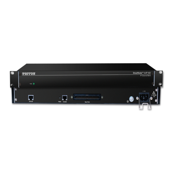
Page 18: Smartnode 4300 Series Rear Panels
SmartNode 4300 Series User Manual 1 • General Information SmartNode 4300 Series rear panels The SmartNode 4300 rear panel ports are shown in figure 3 and described in Table 3 on page 18. Model SN4332 0 -2 0 -6 rt s... -
Page 19: Reset Button Behavior
SmartNode 4300 Series User Manual 1 • General Information Reset button behavior For those SmartNode devices that have a Reset button on the rear panel, its behavior is as follows: • To restart the unit with the current startup configuration—Press for less than 1 second and release the Reset button. -
Page 20: Applications Overview
Chapter 2 Applications Overview Chapter contents Introduction ................................. 21 SmartNode 4300 Series applications........................21 Enterprise FXS concentration and extension over IP and T1/E1..............21 Bulk analog line extensions ..........................22 Legacy MTU/MDU migration to VoIP based networks .................22... -
Page 21: Introduction
SmartNode 4300 Series applications Like all members of the SmartNode family of VoIP solutions, the SmartNode 4300 Series supports all indus- try-standard VoIP signaling protocols, including SIP, H.323, T.38 fax-relay, plus fax- and modem-bypass. The SmartNode 4300 is interoperable with leading softswitches and VoIP servers... -
Page 22: Bulk Analog Line Extensions
SmartNode 4300 Series User Manual 2 • Applications Overview Bulk analog line extensions The SN4300 models used in combination enable enterprises to extend up to 32 analog phone lines over any IP link – be it the public Internet, a leased line or a WiMax link. 600kBit/s bandwidth are enough for 32 simultaneous voice or fax conversations, using G.723 compressed voice transmission. -
Page 23: Hardware Installation
Chapter 3 Hardware installation Chapter contents Introduction ................................24 Planning the installation ............................24 Installation checklist ............................25 Site log ................................25 Network information ............................26 Network diagram ............................26 IP related information ..........................26 Configuration tools ............................26 AC Power Mains .............................26 Location and mounting requirements ......................27 Installing the IpChannel Bank..........................27 Unpacking the Model SN4300 series IpChannel Bank... -
Page 24: Introduction
SmartNode 4300 Series User Manual 3 • Hardware installation Introduction This chapter contains information for planning the installation of the SmartNode 4300 IpChannel Bank with the following installation procedures: • Section “Unpacking the Model SN4300 series IpChannel Bank” on page 27 lists the contents of the shipping •... -
Page 25: Installation Checklist
The installation checklist (see table 4) lists the tasks for installing a SmartNode 4300 Series IpChannel Bank. Make a copy of this checklist and mark the entries as you complete each task. For each SmartNode 4300, include a copy of the completed checklist in your site log. This installation checklist is also available in appen- dix F, “Installation checklist”... -
Page 26: Network Information
Draw a network overview diagram that displays all neighboring IP nodes, connected elements and telephony components. IP related information Before you can set up the basic IP connectivity for your SmartNode 4300 series you should have the following information (see table 6): •... -
Page 27: Location And Mounting Requirements
Location and mounting requirements The SmartNode 4300 is intended to be placed on a desktop or similar sturdy, flat surface that offers easy access to the cables or be installed in a standard 19-inch rack chassis. Allow sufficient space at the rear of the chassis for cable connections. -
Page 28: Connecting Cables
SmartNode 4300 Series User Manual 3 • Hardware installation 5. Place the IpChannel Bank at the desired position in the rack. 6. Secure the IpChannel Bank in position with the mounting screws. 7. Go to section “Connecting cables” on page 28... -
Page 29: Connecting The Ethernet Port
SmartNode 4300 Series User Manual 3 • Hardware installation Connecting the Ethernet port The IpChannel Bank has one 10/100 Ethernet interface for the WAN connection. The Ethernet port will auto-sense the correct speed of the network and automatically negotiate to half- or full-duplex operation. This section describes connecting the IpChannel Bank to the Ethernet LAN via an Ethernet hub or switch. -
Page 30: Connecting The Eia-561 Rs-232 Configuration Port (Dce Configured)
SmartNode 4300 Series User Manual 3 • Hardware installation Connecting the EIA-561 RS-232 configuration port (DCE configured) Install the supplied RJ-45-to-RJ-45 cable with the DB9-RJ45 adapter between the SN4300 IpChannel Bank RS-232 console port (figure 10) and an open serial port on your computer. If you need to assemble your own- cable, refer to the pinout diagram in figure 10. -
Page 31: Installing The Power Cables-Ac Units
SmartNode 4300 Series User Manual 3 • Hardware installation Power cable retainer clip IEC-320 connector (2 places) Grounding stud Figure 11. IEC-320 connector and grounding stud locations 2. Install the grounding wire between the grounding stud (see figure 11) and the grounding source. -
Page 32: Installing The Power Cables-Dc Units
5. Connect the male end of the power cord to an appropriate power outlet. 6. Verify that the green POWER LED is lit. Hardware installation is complete. Refer to chapter 4, “Getting Started with the SmartNode 4300 Series” page 34. Installing the power cables—DC units Mains Voltage: Do not open the case the when the power cord is attached. -
Page 33: Dc Connector, -Dc And +Dc Input View
The 36–72 VDC source is to be reliably connected to earth ground. 6. Verify that the green POWER LED is lit. Hardware installation is complete. Refer to chapter 4, “Getting Started with the SmartNode 4300 Series” page 34. Installing the IpChannel Bank... -
Page 34: Getting Started With The Smartnode 4300 Series
Chapter 4 Getting Started with the SmartNode 4300 Series Chapter contents Introduction ................................35 1. Configure IP address ............................35 Factory-default IP settings ..........................35 Connect to the RS-232 console port .......................35 2. Connecting the SmartNode to the network .......................37 3. Loading the configuration (optional) .........................37 Bootloader................................38 Start Bootloader... -
Page 35: Introduction
SmartNode 4300 Series User Manual 4 • Getting Started with the SmartNode 4300 Series Introduction This chapter leads you through the basic steps to set up a new SmartNode and to download a configuration. Setting up a new SmartNode consists of the following main steps:... -
Page 36: Connecting To The Rs-232 Console Port
SmartNode 4300 Series User Manual 4 • Getting Started with the SmartNode 4300 Series 0 -2 0 -6 rt s lc o o le Console port 0 /0 Model 16F-561 adapter and cable Laptop PC Figure 14. Connecting to the RS-232 Console port Terminal emulation program settings: •... -
Page 37: Connecting The Smartnode To The Network
2. Connecting the SmartNode to the network In general, the SmartNode will connect to the network via the ETH 0/0 (WAN) port. The SmartNode 4300 Series is equipped with an Auto-MDI-X Ethernet port, so you can use a straight-through or crossover cables for host or hub/switch connections (see figure 14). -
Page 38: Bootloader
SmartNode 4300 Series User Manual 4 • Getting Started with the SmartNode 4300 Series In this example we assume the TFTP server on the host with the IP address 172.16.1.11 and the configuration named SN.cfg in the root directory of the TFTP server. -
Page 39: Start-Up With Factory Configuration
SmartNode 4300 Series User Manual 4 • Getting Started with the SmartNode 4300 Series Start-up with factory configuration Step Command Purpose RedBoot> fis load Copies the SmartWare application image from the persistent memory (flash:) to the volatile memory (RAM) from where it will be executed. - Page 40 SmartNode 4300 Series User Manual 4 • Getting Started with the SmartNode 4300 Series Step Command Purpose RedBoot> go Starts the application image that was down- loaded into the volatile memory (RAM). Note With the Bootloader, only the Ethernet interface 0/0 is available. The Boot- loader applies the IP address, subnet mask, and default gateway that were last configured by the Bootloader itself or by another application (e.g.
-
Page 41: Load A New Application Image (Smartware) Via The Serial Link
This type of download takes about 25 minutes since it uses a serial link at only 9600 bps. Additional information For detailed information about configuring and operating guidance, set up procedures, and troubleshooting, refer to the SmartNode Series SmartWare Software Configuration Guide available online at www.patton.com/ manuals. Additional information... -
Page 42: Contacting Patton For Assistance
Chapter 5 Contacting Patton for Assistance Chapter contents Introduction ................................43 Contact information..............................43 Warranty Service and Returned Merchandise Authorizations (RMAs)..............43 Warranty coverage ............................43 Out-of-warranty service ..........................44 Returns for credit ............................44 Return for credit policy ..........................44 RMA numbers ..............................44 Shipping instructions ..........................44... -
Page 43: Introduction
SmartNode warranty and obtaining a return merchandise authorization (RMA). Contact information Patton Electronics offers a wide array of free technical services. If you have questions about any of our other products we recommend you begin your search for answers by using our technical knowledge base. Here, we... -
Page 44: Out-Of-Warranty Service
RMA#: xxxx 7622 Rickenbacker Dr. Gaithersburg, MD 20879-4773 USA Patton will ship the equipment back to you in the same manner you ship it to us. Patton will pay the return shipping costs. Warranty Service and Returned Merchandise Authorizations (RMAs) -
Page 45: Compliance Information
Appendix A Compliance Information Chapter contents Compliance ................................46 EMC compliance: ............................46 Low Voltage Directive (Safety): ........................46 PSTN: ................................46 Radio and TV Interference (FCC Part 15) ......................46 CE Declaration of Conformity ..........................46 Authorized European Representative ........................46... -
Page 46: Compliance
CE Declaration of Conformity Patton Electronics, Inc declares that this device is in compliance with the essential requirements and other rele- vant provisions of Directive 1999/5/EC. The Declaration of Conformity may be obtained from Patton Elec- tronics, Inc at www.patton.com/certifications. -
Page 47: Specifications
Appendix B Specifications Chapter contents Voice connectivity - FXS ............................48 Voice connectivity - FXO ............................48 Ethernet interface ..............................48 Console port................................48 FXS/FXO ports ..............................48 PPP and Frame-Relay support ..........................49 Voice processing (signaling dependent) .........................49 Fax and modem support............................49 Voice signaling ..............................50 Voice routing-session router ..........................50 Management... -
Page 48: Voice Connectivity - Fxs
SmartNode 4300 Series User Manual B • Specifications Voice connectivity - FXS 2-wire Loopstart Short haul loop 1.1 km @3REN EuroPOTS (ETSI EG201 188) Programmable AC impedance, feeding, and ring voltage; on-hook voltage 48 VDC Caller-ID Type-1 FSK and ITU V.23/Bell 202 generation... -
Page 49: Ppp And Frame-Relay Support
SmartNode 4300 Series User Manual B • Specifications PPP and Frame-Relay support • Frame-Relay (8 PVCs) • RFC1440, FRF.12 fragmentation • LMI, Q.933D, ANSI 617D, Gang of Four (an encapsulation method created by the four companies: Cisco, Northern Telecom, StrataCom, and DEC which differs from the IETF encapsulation) •... -
Page 50: Voice Signaling
SmartNode 4300 Series User Manual B • Specifications Voice signaling H.323v4: • RAS, H.225, H.245 • Fast-connect, early H.245 • Gatekeeper autodiscovery • Alias registration • Overlap sending • Empty capability set (call transfer, hold) • H.323v1 call transfer, hold •... -
Page 51: Operating Environment
SmartNode 4300 Series User Manual B • Specifications Operating environment Temperature Operating range: 32–104°F (0–40°C) Internal temperature: Available in real-time on the IpChannel Bank web pages Humidity 5 to 90% relative humidity (RH), non-condensing Altitude Maximum operating altitude: 15,000 feet (4,752 meters) System •... -
Page 52: Identification Of The Smartnode Devices Via Snmp
SmartNode 4300 Series User Manual B • Specifications Identification of the SmartNode devices via SNMP All SmartNode devices have assigned sysObjectID (.iso.org.dod.internet.mgmt.mib-2.system.sysObjectID) numbers (see table 9). Table 9. SmartNode Models and their Unique sysObjectID SmartNode Model SysObjectID SN4308/JS/RUI 1.3.6.1.4.1.1768.100.4.14.1 SN4312/JS/RUI 1.3.6.1.4.1.1768.100.4.14.2... - Page 53 Appendix C Port Pin-outs Chapter contents Introduction ................................54 Console port................................54 Ethernet 10Base-T and 100Base-T port ........................54 FXS/FXO ports ..............................55...
-
Page 54: C Port Pin-Outs
SmartNode 4300 Series User Manual C • Port Pin-outs Introduction This section provides pin-out information for the ports of the SmartNode. Console port Configuration settings: Asynchronous data rate of 9600 bps, 2 bits, no parity, 1 stop bit, no flow control... -
Page 55: Fxs/Fxo Ports
SmartNode 4300 Series User Manual C • Port Pin-outs FXS/FXO ports The FXS/FXO ports are accessed through a 64-pin RJ-21X connector (see table 10 for pin-outs) or through a 50-pin RJ-21X connector (see Table 11 on page 57 for pin-outs) located on the rear panel of the IpChannel Bank. - Page 56 SmartNode 4300 Series User Manual C • Port Pin-outs Table 10. Band marked wiring key for the 64-pin RJ-21X connector (Continued) 64 Pin Tip & Ring Pair Number Positions Tip 17 Pair 17 Ring 17 Tip 18 Pair 18 Ring 18...
-
Page 57: Band Marked Wiring Key For The 50-Pin Rj-21X Connector
SmartNode 4300 Series User Manual C • Port Pin-outs Table 11. Band marked wiring key for the 50-pin RJ-21X connector 50 Pin Tip & Ring Pair Number Positions Tip 1 Pair 1 Ring 1 Tip 2 Pair 2 Ring 2... - Page 58 SmartNode 4300 Series User Manual C • Port Pin-outs Table 11. Band marked wiring key for the 50-pin RJ-21X connector (Continued) 50 Pin Tip & Ring Pair Number Positions Tip 19 Pair 19 Ring 19 Tip 20 Pair 20 Ring 20...
-
Page 59: Factory Configuration
Appendix D Factory Configuration Chapter contents Introduction ................................60... -
Page 60: Introduction
SmartNode 4300 Series User Manual D • Factory Configuration Introduction The factory configuration settings for SmartNode 4300 Series devices are as follows: #----------------------------------------------------------------# # 4300 Series # Factory configuration file #----------------------------------------------------------------# sntp-client ... -
Page 61: E End User License Agreement
Appendix E End user license agreement Chapter contents End User License Agreement ..........................62 1. Definitions ..............................62 2. Title ................................62 3. Term ................................62 4. Grant of License ............................62 5. Warranty ..............................62 6. Termination ..............................63 7. Other licenses .............................63... -
Page 62: End User License Agreement
(including, without limitation, damages for loss of business profits, business interruption, loss of business information, or other pecuniary loss) arising out of the use of or inability to use the Program(s), even if Patton Electronics Company has been advised of the possibility End User License Agreement... -
Page 63: Termination
A) The End User may terminate this agreement by returning the Designated Equipment and destroying all copies of the licensed Program(s). B) Patton Electronics Company may terminate this Agreement should End User violate any of the provi- sions of section on page 62. -
Page 64: Installation Checklist
Appendix F Installation checklist Chapter contents Introduction ................................65... -
Page 65: Introduction
Introduction This appendix lists the tasks for installing a SmartNode 4300 IpChannel Bank (see table 12). Make a copy of this checklist and mark the entries as you complete each task. For each IpChannel Bank, include a copy of the completed checklist in your site log. -
Page 66: Accessories
Appendix G Accessories Chapter contents Introduction ................................67... -
Page 67: Introduction
SmartNode 4300 Series User Manual G • Accessories Introduction The cables listed in table 13 are available as accessories for the SmartNode 4300 Series products. Table 13. Accessory cables Description Part Number 64-pin telco to open end cable, 10 ft/3.048 m (64-pin FSX port)
Need help?
Do you have a question about the SmartNode 4300 and is the answer not in the manual?
Questions and answers