Table of Contents
Advertisement
Available languages
Available languages
Quick Links
Download this manual
See also:
Programming Manual
Advertisement
Chapters
Table of Contents

Related Manuals for GRAUPNER MX-12 - PROGRAMMATION


Summary of Contents for GRAUPNER MX-12 - PROGRAMMATION
-
Page 2: Table Of Contents
Servoweg-Anzeige............25 zwecken, kann ohne Vorankündigung geändert werden. Funktionsmodus HUBSCHRAUBERMODELL Bitte erkundigen Sie sich bei der Gemein- Die Firma GRAUPNER übernimmt keine Verantwortung deverwaltung die zuständige Entsorgungs- Dual Rate und Expo............. 26 oder Haftung für Fehler bzw. Ungenauigkeiten, die im stelle. -
Page 3: Sicherheitshinweise
Zubehörteile verwendet werden. Verwenden Sie nicht gekürzt oder verlängert werden. Die Antenne sollte können zum unverhofften Anlaufen des Motors und/oder immer nur zueinander passende, original GRAUPNER möglichst weit weg von Elektromotoren, Rudermaschi- zu herumfliegenden Teilen führen, die Sie erheblich Steckverbindungen gleicher Konstruktion und gleichen nen, metallischen Gestängen, Strom führenden Leitun-... - Page 4 Sicherheitshinweise Einbau der Servos Die Doppelbelegung eines Frequenzkanals verursacht Diese Überprüfung bei laufendem Motor wiederholen, Servos stets mit den beigefügten Vibrationsdämpfer- Störungen und kann andere Modelle zum Absturz während ein Helfer das Modell festhält. gummis befestigen. Nur so sind diese vor allzu harten bringen.
- Page 5 Komponenten und Zubehör pazitätsminderung führen, deshalb sollten Stromquellen angebracht, die auf Grund ihrer niedrigen Windungs- Die Firma GRAUPNER GmbH & Co. KG als Hersteller spätestens alle 6 Monate auf Kapazität überprüft und zahlen im Blockierfall ein Vielfaches ihres Nennstromes empfiehlt, Komponenten und Zubehörprodukte zu ver- bei deutlichem Leistungsabfall ersetzt werden.
-
Page 6: Einführung
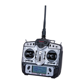
Computer System mx-12 6-Kanal Digital-Proportional-Fernlenkset • Universell einsetzbares Fernlenksystem voll ausge- baut • Hochwertiges Fernlenksystem für F3A-, F3B-, F3C-, F3E-, Delta- und V-Leitwerk-Modelle. Auf 6 Steuer- funktionen, 4 proportional, trimmbar, 2 schaltbar, voll ausgebaut • Komfort-Mode-Selector zur einfachen Umschaltung des Betriebs-MODES 1-4 (Gas rechts/links). Alle Mixer-, Einstell- und Reverse- Speicherdaten werden automatisch mit umgestellt. - Page 7 Die Sets enthalten: 4179.1 Lehrer/Schüler Kabel für mx-12 Kanalraster 10 kHz Microcomputer-Sender mx-12 mit eingebautem NiMH- Für die Kombination von Graupner Empfindlichkeit ca. 10 µV Akku 8 NH-1700 TX, Empfänger R 700 der entspre- Handsendern mit DSC-Buchse Ansteckbare Servos chenden Frequenz, Quarzpaar aus dem entspre- 3290.8...
-
Page 8: Laden Des Senderakkus
Die auf dem Markt befindlichen Ladekabel anderer Her- den durch Überhitzung im Sender zu vermeiden. erfolgt in gleicher Weise. steller weisen oft abweichende Polaritäten auf. Verwen- Keinesfalls Lötstellen auf der Senderplatine mit den Sie deshalb nur original GRAUPNER-Ladekabel. Standard-Ladegeräte metallischen Gegenständen berühren! Best.-Nr. 6422 Minilader 2 Ladestrom Best.-Nr. -
Page 9: Senderbeschreibung
(für HELI) bzw. Sollten Sie dennoch einen Knüppel in einer anderen Fahrwerk (für HELI+ Länge benötigen, so erkundigen Sie sich im guten Fach- Trainer Schalter Flächenmodell) handel nach dem GRAUPNER Knüppelsortiment. Querruder- D/R Schalter (Roll) Stellschraube linker Knüppel Motor AUS-... - Page 10 Gasknüppel Ladebuchse für Die Voreinstellung für den Gasknüppel ist die Raster- Senderakku führung. Wenn Ihnen diese Einstellung nicht zusagt, (Graupner 8NH-1700 TX können Sie sie mit den nachfolgenden Arbeitsschritten Best-Nr. 3414 beiliegend) ändern. Sie benötigen dazu einen Kreuzschlitzschrau- Batteriefach-Abdeckung Batteriefach-Abdeckung bendreher und eine Flachzange.
-
Page 11: Direct Servo Control
Direct Servo Control (DSC) wegen) und von seinem Lager abheben. Direct Servo Control Gründe, mit DSC zu arbeiten: 8. Hebel und Feder in umgekehrter Reihenfolge an der Für eine saubere DSC-Verbindung bitte beachten: 1. Mit DSC können Sie die Funktion Ihrer Steuerele- rechten Knüppeleinheit einbauen (das Lager befindet 1. -
Page 12: Einbau Und Anschlüsse
FLAP Ihr Fernsteuersystem muss unbedingt richtig im Modell Querruder (links) (AUX1) eingebaut sein. Hier einige Vorschläge zum Einbau der AKKU GRAUPNER-Ausrüstung: 1. Wickeln Sie den Empfänger in Schaumgummi von Fahrwerks- mindestens 6mm Dicke. Fixieren Sie den Schaum GEAR Kanal gummi mit Gummibändern am Empfänger, um ihn bei einem Crash oder einer harten Landung zu schützen. - Page 13 Einbau und Anschlüsse Helikoptermodelle AUX1 Roll/Pitch (links) AKKU GYRO GYRO Fahrwerkskanal- GEAR Servo RUDD Heckrotorservo SCHALTERKABEL ELEV Nickservo bzw. LADEBUCHSE Nick/Pitch (hinten) AILE EMPFÄNGER ANTENNE Rollservo bzw. Roll/Pitch (rechts) THRO Gasservo WARNUNG Antenne nicht kürzen! Einbau und Anschlüsse HELIKOPTERMODELLE...
-
Page 14: Tasteneingaben Und Anzeige
Sie die gewünschte Funktion an. wenden Sie sich dazu an Ihren Händler oder an eine GRAUPNER-Servicestelle. Die Anschrift Ihrer GRAUPNER-Servicestelle finden Sie auf Seite 47. Das Wechseln der Batterie darf nur von Ihrem Fach- händler durchgeführt werden, da bei fehlerhaftem... -
Page 15: Eingabemodus, Eingabefunktionen
Eingabemodus, Eingabefunktionen Normalmodus Modernste digitale Trimmung - Advanced Digital Trim (A.D.T.) Name des Modells Die digitalen Trimmfunktionen der mx-12 greifen auf Sender-Akkuspannung Sender-Akkuspannung Sender-Akkuspannung Sender-Akkuspannung (falls vorhanden) die Direct Access-Technik mit Statusanzeige auf dem Display zurück, d.h. in der Normalanzeige wird bei Än- Modelltyp : Flächenmodell derungen an einem Trimmhebel automatisch die neue... -
Page 16: Funktionsmodus
Funktionsmodus Sie gelangen in den Funktionsmodus, indem Sie die Flächenmodell Helikoptermodell Helikoptermodell UP- und SELECT-Tasten gleichzeitig gedrückt halten und danach den Sender einschalten. In der Anzeige steht 1. Dual Rate und EXPonential 13. Dual Rate & EXPonential nun das zuletzt aktive Programm. Durch Drücken der UP- oder der DOWN-Taste durchlaufen Sie nacheinan- 2. -
Page 17: Systemmodus
Systemmodus Sie gelangen in den Systemmodus, indem Sie die Flächenmodell Helikoptermodell Helikoptermodell UP- und SELECT-Taste gleichzeitig gedrückt halten und danach den Sender einschalten. In der Anzeige steht nun das zuletzt aktive Programm. Durch Drücken der 26. MODEL SELect 26. MODEL SELect UP- oder der DOWN-Taste durchlaufen Sie nacheinan- (Modell auswählen) (Modell auswählen) -
Page 18: Funktionsmodus (List)
Funktionsmodus (List) Sie gelangen aus dem Funktionsmodus in den Funkti- onslisten-Modus, indem Sie den Sender EIN- schalten, dann gleichzeitig die UP und SELECT gedrückt halten. Mit der DOWN- und SELECT Taste scrollen Sie durch: Flächenmodell Helikoptermodell Helikoptermodell FUNKTIONSLISTE 1 FUNKTIONSLISTE 1 FUNKTIONSLISTE 2 FUNKTIONSLISTE 2 SYSTEMLISTE 1... -
Page 19: Funktionsmodus Flächenmodell
Funktionsmodus FLÄCHENMODELL Dual Rate und Exponentialfunktion; Servorichtungs-Umkehrung Dual Rate und Expo Dual Rate und Expo 8. Durch Drücken der DOWN-Pfeiltaste gelangen Sie ins Bild SERVO TRAVEL (Servoweg). Kanal 9. Durch das gleichzeitige Drücken der DOWN und Dual Rate-Position AILE: Querruder Zum Menü... -
Page 20: Servo-Mitteneinstellung (Sub Trim)
Funktionsmodus FLÄCHENMODELL Servo-Mitteneinstellung (Sub Trim); Servoweg (Travel Adjust) meter. +/- 125% (+/- 30° Servoausschlag) justieren. Die Sub Servoweg (Travel Adjust) Servoweg (Travel Adjust) Notieren Sie dabei die Ausschlagrichtung jeder Trim Funktion hilft Ihnen, den Servoarm präzise auf Steuerfläche. Neutral einzustellen, wenn er sich nicht durch einfaches 5. - Page 21 Funktionsmodus FLÄCHENMODELL Mischer Höhenruder auf Klappen; Mischer Quer- auf Seitenruder die Sie einstellen wollen. Ein Pfeil links vom Travel „Immer AN“ aus. RIGHT FWD: Fahrwerksschalter nach vorn AN RIGHT REA: Fahrwerksschalter nach hinten AN Adjust - Wert zeigt die derzeit eingestellte Richtung 7.
-
Page 22: Leerlaufschalter (Throttle Cut)
Funktionsmodus FLÄCHENMODELL Leerlaufschalter (Throttle Cut); Klappensystem Leerlaufschalter (Throttle Cut) Leerlaufschalter (Throttle Cut) 5. Mit der UP-Taste wechseln Sie zur Funktion Zum Menü Leerlauf Wert ändern/Schalter Diese Funktion bindet den Schalter THRO CUT an AIL > RUD MIX. wählen Zum Menü Ele den Druckknopf oben rechts am Sender. -
Page 23: Mischer Für Querruder-Differenzierung
Funktionsmodus FLÄCHENMODELLE Mischer für Querruderdifferenzierung; Programmierbare Mischer (1~4) 7. Wechseln Sie durch Drücken der UP-Taste zur Differenzierungswert: Differenzierungswert: Funktion MIX 1. Norm. 8. Sie können die Funktion FLAP SYSTEM verlassen, indem Sie DOWN und SELECT gleichzeitig drücken. Diff. Mischer für differenzierte Querruder (Differential) Mischer für differenzierte Querruder (Differential) Dieses Servo mit AUX 1/ Quer- Dieses Servo mit dem Querru-... -
Page 24: Fail Safe
Funktionsmodus FLÄCHENMODELL Fail Safe aus, und das Seitenruder läuft automatisch in die Rich- So kommen Sie zur Funktion Programmierbare Display angezeigt. tung und mit dem Wert, der im Mixer vorgegeben ist. Mischer: Das Mischen erfolgt proportional, d.h. kleine Eingaben 1. Ein/Aus-Schalter auf EIN stellen. Einstellen des Offset für den Mischerkanal: am Master ergeben kleine Ausschläge am Slavekanal. -
Page 25: Servoweg-Anzeige
Funktionsmodus FLÄCHENMODELL Servoweg-Anzeige Funktion SERVO TRAVEL. Anzeige 4: Seitenruder Anzeige der Fail Safe Seite 8. Wechseln Sie durch Drücken von UP zur Funktion Anzeige 5: Fahrwerk MIXING FUNCTIONS. Anzeige 6: Klappen 9. Sie können die Funktion FAIL SAFE durchgleichzei- 4. Mit der UP-Taste wechseln Sie in die D/R & EXP tiges Drücken von DOWN und SELECT verlassen. -
Page 26: Funktionsmodus Hubschraubermodell
Funktionsmodus HUBSCHRAUBERMODELL Dual Rate und Expo; Servorichtungs-Umkehrung Dual Rate und Expo Dual Rate und Expo weg, 100% ist der volle Expowert. Je höher der 8. Durch Drücken der DOWN-Pfeiltaste kommen Sie Expowert, desto weniger Servobewegung erfolgt bei zum Bild SERVO TRAVEL (Servoweg). Kanal: Steuerbewegungen um den Nullpunkt herum. -
Page 27: Servo-Mitteneinstellung (Sub Trim)
Funktionsmodus HUBSCHRAUBERMODELL Servo-Mitteneinstellung (Sub Trim); Servoweg (Travel Adjust) 5. Legen Sie fest, für welchen Kanal Sie die Aus- 0-150% (0°-60° Servoausschlag) vom Neutralpunkt aus, Zum Menü Servo- weg-Einstellung schlag-Umkehrfunktion haben wollen,und wählen Wert ändern und kann nach jeder Richtung gesondert eingestellt Zum Menü... -
Page 28: Taumelscheiben Mischer (Ccpm-Ts)
Auswahlfenster im Systemmodus ausgewählt werden. versetzt sind. Diese CCPM-Form ist die verbreiteste, on markiert ist. Wenn kein TS-Typ gewählt ist, wird diese Option sie ist bei Graupner und bei anderen Herstellern zu 5. Mit (+) oder (-) erhöhen oder verringern Sie die übersprungen. finden. -
Page 29: Autorotation (Throttle Hold)
Funktionsmodus HUBSCHRAUBERMODELL Leerlaufschalter; Autorotation Ch6 = Linkes TS-Servo Achtung: Durch Drücken auf CLEAR wird die Motor AUS-Funktion gesperrt und bis zur Reaktivie- rung abgestellt. 4. Wechseln Sie mit der DOWN-Taste zur Mischerfunk- tion TRAVEL ADJ . 5. Wechseln Sie mit der UP-Taste zur Funktion Gas Servo Position für Autorotations „Motor AUS“-Schalter... -
Page 30: Gaskurven (Throttle Curve)
Funktionsmodus HUBSCHRAUBERMODELL Gaskurven 7. Wechseln Sie mit der DOWN-Taste zur Funktion Der Sender ist werksseitig auf die Gaskurve eingestellt, Achtung: In jeder Kurve ist als Werkseinstellung für THROTTLE CUT. die im Bild unten durchgehend gezeichnet ist. Die Ein- die Punkte 1 und 3, also bei 25% und 75%, 8. -
Page 31: Pitchkurven (Pitch Curve)
Funktionsmodus HUBSCHRAUBERMODELL Pitchkurven Hinweis: Änderungen am Gas-Trimmhebel wirken sich Schwebegas-Trimmung Zum Menü Drehzahl- Motorleistung Arbeitsbereich (Parallel) Arbeitsbereich (Parallel) mischer Wert ändern/Schalter- nicht auf die Eingabewerte für einen der stellung Zum Menü Gaskurve Punkte auf der Gaskurve aus. Sie bewirken POS-Wert auf 0 nur Anpassungen der Stellung für die Leer- Zu ändernde- zurücksetzen oder... - Page 32 Funktionsmodus HUBSCHRAUBERMODELL Pitchkurven drücken Sie zuerst SELECT, um die Funktion NORM Pitch zu markieren, und dann auf (+) od. (-), um die Funk- tion STUNT anzuwählen. Führen Sie die Schritte 4 und 5 so oft aus, bis der Vorgang abgeschlossen ist. 7.
-
Page 33: Statischer Drehmomentausgleich Dma
Funktionsmodus HUBSCHRAUBERMODELL Statischer Drehmomentausgleich „DMA“ (nicht für Heading-Lock-Gyrosysteme) Statischer Drehmomentausgleich Statischer Drehmomentausgleich (Revo Mix) (Revo Mix) 4. Durch Drücken der SELECT-Taste markieren Sie Programmierbare Mischer (1~2) rogrammierbare Mischer (1~2) (nicht für Heading-Lock-Gyrosysteme) oder die Flugphasenschalter-Stellung. Wenn der Mit der mx-12 können 2 programmierbare Mischer für Die Funktion Statischer Drehmomentausgleich be- Flugmodusschalter und der Gasknüppel jeweils in beliebig viele Zwecke benutzt werden. -
Page 34: Fail Safe
Funktionsmodus HUBSCHRAUBERMODELL Fail Safe Der Mischer-Offset dient dazu,den Neutralpunkt des Einstellen der Mischwerte: Mischen leichter verstehen. Seine Einsatzmöglich Slave-Kanals neu festzulegen. 8. Drücken Sie den Master-Knüppel in die Richtung, in keiten werden nur durch Ihre Phantasie begrenzt. Slave-Kanal der Sie mischen wollen, drücken Sie dann die (+) Master-Kanal oder (-) -Taste, um den Mischwert für den Slave-Ka- Fail Safe... -
Page 35: Servoweg Anzeige
Funktionsmodus HUBSCHRAUBERMODELL Servoweg Anzeige Achtung: Die Failsafe-Funktion arbeitet Servobezogen, 100% nicht Funktionsbezogen. Neutral Vorsicht bei gemischten Taumelscheibenanlenkungen! So kommen Sie zur Funktion Fail Safe 1. Stellen Sie den Ein/Aus-Schalter auf EIN. 2. Wählen Sie den Funktionsmodus durch gleichzeiti- ges Drücken von DOWN und SELECT an. Drücken Sie dann die UP oder DOWN-Taste, bis Zum Menü... -
Page 36: Systemmodus
System-Modus Modell-Auswahl; Eingabe des Modellnamens Modell-Auswahl (Model Select) Auswahl (Model Select) angezeigt wird,können Sie durch gleichzeitiges So kommen Sie zur Funktion Model Select: Das System mx-12 bietet Speicherplatz für 10 völ- Drücken von DOWN und SELECT die Funktion 1. Halten Sie UP und SELECT gleichzeitig gedrückt lig verschiedene Modelle. -
Page 37: Modelltyp Auswahl (Model Type)
System-Modus Modelltyp-Auswahl; Modell kopieren Modelltyp-Auswahl Modelltyp-Auswahl (Model Type) (Model Type) indem Sie gleichzeitig auf DOWN und SELECT wählen, auf den das aktuelle Modell kopiert werden Die mx-12 ist eine leistungsfähige Fernsteuerung mit drücken. soll. allen Funktionen sowohl für Hubschraubermodelle als 4. -
Page 38: Modulation
4. Wenn Sie auf CLEAR drücken, wird die Steueran Die Funktion Wahl der Modulation (Modulation Selection) Modulationsart oben rechts angezeigt. ordnung auf die Werkseinstellung (Mode 1) zurück- gibt Ihnen die Möglichkeit, eine Reihe von GRAUPNER gesetzt. - Empfängern mit Ihrer mx-12 anzusprechen. Sie können Steueranordnung (Stick Mode) teueranordnung (Stick Mode) 5. -
Page 39: Lehrer/Schüler-Funktion (Trainer)
Verbindung mit einem weiteren, mit Pilot Link 4179.1 Lehrer/Schüler Kabel für mx-12 ausgestatteten Sender als Slave fungieren kann. Für die Kombination von Graupner Normalmodus: - In dieser Betriebsart arbeitet der Handsendern mit DSC-Buchse Sender als konventionelles „Buddy-Box“ - System. Der 3290.8... -
Page 40: Schalter-Auswahl (Switch Select)
System-Modus Schalter-Auswahl Wenn andere Sendermodelle benutzt werden, In der Funktion Modulation (Flächenmodelle): INHIBIT ist es nötig, daß der Slave-Sender im PPM- Dual Rate Der Fahrwerkskanal ist gesperrt und auf Mitte gesetzt, Modus arbeitet, damit er mit der mx-12 zusam- D/R INDIVID (Voreinstellung) D/R INDIVID (Voreinstellung) er kann so als Slave-Kanal fürs Mischen fungieren. -
Page 41: Leitwerkstyp Auswahl (Wing Type)
System-Modus Leitwerkstyp-Auswahl COM ELEV ELEV D/R ELEV D/R sie gleichsinnig ausschlagen und so als Klappen oder In diesem Modus sind die Dual Rate-Werte für Quer-, Der Flugmodus wird mit dem Höhenruder-Dual-Rate- Spoiler dienen. Seiten- und Höhenruder im Schalter ELEV D/R zusam- Schalter gewählt. - Page 42 Als weiteren Leitwerstyp für die mx-12 gibt es den mit dem Höhenruderanschluß (ELEV) Ihres Feintrimmung und Querruderdifferenzierung Mischertyp Elevon. Auch er braucht 2 Flächenservos. GRAUPNER-Empfängers. einrichten. Es gibt jedoch kein Höhenruder am Modell. Stattdessen 6. Prüfen Sie, ob die Servos in der richtigen Richtung Hinweis: Die Einstellung des Servoausschlags nach bewirkt eine Bewegung Höhensteuerknüppel, daß...
- Page 43 Systemmodus Hinweis: Die Ausschlagrichtung jedes einzelnen Ser- 11. Sie können die Funktion WING TYPE verlassen, richtige Auf/Ab-Steuerbefehl ausgeführt wird. Sollten vos läßt sich über die Funktion Servo-Um- indem Sie gleichzeitig auf DOWN und SELECT die Ruder sich nicht korrekt bewegen, benützen Sie kehrung einstellen.
- Page 44 Zurück zur Werksein- stellung Es gibt folgende TS-Optionen: 1 Servo: Nicht-CCPM, mechanische Mischung 2 Servo/180° CCPM 3 Servo/120° CCPM (System GRAUPNER, weitver- breitet ) 4 Servo/90° CCPM So wählen Sie die TS-Typen: 1. Halten Sie DOWN und SELECT gleichzeitig ge- drückt und stellen Sie dabei den Ein/Aus-Schalter...
-
Page 45: Zulässige Betriebsfrequenzen
Zulässige Betriebsfrequenzen, lieferbare Quarze, Frequenzflaggen Der Betrieb der Fernsteueranlage ist nur für das jeweilige EU-Land national zugelassenen Frequenzen/Kanälen zulässig. Bitte beachten Sie die jeweilige Gesetzeslage. Das Benutzen der Fernsteueranlage auf davon abweichenden Frequenzen/Kanälen ist verboten /PN.JH-01 43963 Id.-Nr. Zulässige Betriebsfrequenzen... -
Page 46: Zulassungsurkunde Konformitätserklärung
Zulassungsurkunde Konformitätserklärung Zulassung/Konformität... -
Page 47: Garantieurkunde
Sur ce produit nous accordons une garantie de mois Servicestellen / Service / Service après-vente Die Fa. Graupner GmbH & Co. KG, Henriettenstraße 94- Cette garantie ne remet pas en cause les droits et 96, 73230 Kirchheim/Teck gewährt ab dem Kaufdatum prétentions légaux du consommateur. - Page 50 Function mode HELICOPTER If you don’t know the location of your nearest of the GRAUPNER company. GRAUPNER accepts no Dual Rates and Exponential.........26 disposal centre, please enquire at your local responsibility or liability for errors or inaccuracies which Servo Reversing............
-
Page 51: Safety Notes
Even small models can cause serious personal injury genuine matching GRAUPNER connectors of the same The receiver aerial is permanently attached to the recei- and damage to property if they are handled incompe- design with contacts of the same material. - Page 52 Safety notes Installing the servos Pre-flight checking correctly and in the appropriate direction to the transmit- Always install servos using the vibration-damping If there are several modellers at the site, check carefully ter commands at a suitable ground range. grommets supplied. The rubber grommets provide with all of them that you are the only one on „your“...
- Page 53 As manufacturers, we at GRAUPNER are not in a positi- depending on the motor type; the sparking generates on the working of the radio control system.
-
Page 54: Introduction
Computer system mx-12 6 channel digital proportional radio control system • All-purpose radio control system, fully expanded as standard • High-quality radio control system for F3A, F3B, F3C, F3D, F3E model aircraft, deltas and V-tail models. Fully expanded, offering 6 channels: 4 proportional channels with trims, 2 switched channels •... -
Page 55: Description Of Radio Control System
Servo functions 3290.8 Trainer lead for mx-12 C 577 servo, switch harness, battery holder for receiving For use with Graupner mc-… trans- system Temperature range -15° ... + 55° C mitters with trainer sockets Six-channel micro-computer radio control system, Aerial length approx. -
Page 56: Charging The Transmitter Battery
If you intend to charge the transmitter battery at by other manufacturers are often made up with the op- a current higher than 1.5 A, the battery must be posite polarity. For this reason use genuine GRAUPNER removed beforehand, otherwise the transmitter charge leads exclusively. -
Page 57: Transmitter Description
Flap Mixing SW (For AIRPLANE) (for AIRPLANE) 2mm set screw. If you desire longer sticks, GRAUPNER Carrying Bar offers a stick that is approximately one inch longer than standard. This stick, crafted from bar stock aluminum, is available at your local GRAUPNER dealer. - Page 58 If you don`t like this feeling, please follow the following Charging Jack instruction to change it. You will be required a posidrive for transmitter batteries (Graupner 8NH-1700 TX screwdriver and a pair of tweezers; Order No. 3414 included) Battery Cover 1.
-
Page 59: Direct Servo Control
Direct servo control (DSC) 9. The left side of the right-hand assembly has a metal For proper DSC hook-up and operation: Why you should use the DSC function: strip which provides the ratched friction action. This 1. Leave the transmitter power switch in the OFF posi- 1. -
Page 60: Connections And Installations For Airplane
It is extremely important that your radio system be cor- CHANNEL (AUX1) rectly installed in your model. Here a few suggestions BATTERY installing your GRAUPNER equipment: 1. Wrap the receiver in protective foam rubber that GEAR is no less than 3/8 inch thick. Secure the foam to GEAR CHANNEL the receiver with #64 rubber bands. -
Page 61: For Helicopter
Connections and installations For Helicopter AUX1 PITCH SERVO BATTERY GYRO GEAR GEAR CHANNEL RUDD RUDDER SERVO SWITCH HARNESS ELEV ELEVATOR SERVO CHARGING JACK AILE RECEIVER ANTENNA AILERON SERVO R700 RECEIVER THRO THROTTLE SERVO WARNING Do not cut or fold the antenna! Connections and installations... -
Page 62: Key Input And Display
Key input and display; Alarm and error display Battery alarm and display When the transmitter voltage drops below 9.0 volts DC, the display flashes “BATT LOW“ and an alarm sounds. If you are flying when this occurs, land immediately. Up Key Increase Key Backup error display Down Key... -
Page 63: Input Mode And Function
Input mode and function Normal mode Advanced Digital Trim (A.D.T.) The mx-12 digital trims feature the Direct Access display Model Name function. While at the Normal display screen, if a trim Transmitter voltage (If there is) lever is moved, the screen will automatically change to display the graphic position for the trim being adjusted. -
Page 64: Function Mode
Function mode To enter the Function mode, switch the transmitter AIRPLANE HELICOPTER power switch to the On position. Press the Down and Select keys simultaneously, and the display will show 1. Dual Rate & EXPonential 13. Dual Rate & EXPonential the last active program. -
Page 65: System Mode
System mode To enter the System mode, press the Down and AIRPLANE HELICOPTER Select keys simultaneously, then turn the power switch to the ON position. The display will show the last active program. Pressing either the Up or Down key then 26. -
Page 66: List Mode
List mode To enter the Function List mode from the Function mode, HELICOPTER switch the transmitter power switch to the ON position. FUNCTION LIST 1 Press the Up und Select keys simultaneously. To scroll the functions, first press the Down and Select keys. FUNCTION LIST 1 FUNCTION LIST 2 FUNCTION LIST 2... -
Page 67: Function Mode Airplane
Function mode AIRPLANE Dual Rates and Exponential; Servo Reversing Dual Rates and Exponential 7. Press the Up arrow key to access the REVERSING SW menu. Channel 8. Press the Down arrow key to access the SERVO AILE: AILERON D/R POSITION Go to Reversing ELEV: ELEVATOR TRAVEL SCREEN. -
Page 68: Sub Trim
Function mode AIRPLANE Sub Trim; Travel Adjust 3. Press either the Up or Down key until TRAVEL ly adjustable for all six channels with a range of +/- Travel Adjust ADJ appears in the upper portion of the LCD. 125% (+/- 30 degrees servo travel). 4. -
Page 69: Elevator To Flap Mixing
Function mode AIRPLANE Elevator to flap mixing; Aileron to rudder mixing highlighted. Up key. RIGHT FWD: Gear SW Forward side On 5. Move the appropriate control stick (lever, switch, 8. Access the AIL RUD MIX Mixing function by pres- RIGHT REA: Gear SW Rear etc.) to the right or left of center to the direction of... -
Page 70: Throttle Cut Switch
Function mode AIRPLANE Throttle Cut switch; Flap System Throttle Cut switch 5. Access the AIL RUD MIX function by pressing the Go to Throttle cut Change value/Select menu This function assigns the Throttle Cut switch to the push Up key. switch Go to Ele... -
Page 71: Differential Aileron Mixing
Function mode AIRPLANE Differential aileron mixing; Programmable Mixing (1~4) the Down key. Differential Value direction and to the value input. Mixing is proportional, 7. Access the MIX 1 function by pressing the Up key. so small inputs of the master channel will produce small 8. -
Page 72: Fail Safe
Function mode AIRPLANE Fail Safe Accessing the Programmable Mixing Function Setting the Mixing Channel Offset Fail Safe Side Display 1. Place the transmitter switch in the ON position. 1. Press the Select key until offset is highlighted. The 2. Press the Down and Select keys simultaneously display will show the current mixing channels at the to enter the Function mode. -
Page 73: Servo Travel Screen
Function mode AIRPLANE Servo Travel Screen Up key. Indicator 3: Elevator 8. Access the MIXING FUNCTIONS function by pres- Indicator 4: Rudder sing the Up key. Indicator 5: Gear 9. Exit the FAIL SAFE function by pressing the Down Indicator 6: Flap and Select keys simultaneously. -
Page 74: Function Mode Helicopter
Function mode HELICOPTER Dual Rate and Exponential; Servo Reversing Dual Rates and Exponential ential value, the less servo action or sensitivity you will 8. Press the Down arrow key to access the SERVO notice around the neutral setting. TRAVEL SCREEN. Channel Either switch position may be selected as the low or 9. -
Page 75: Sub Trim
Function mode HELICOPTER Sub Trim; Travel Adjust corresponding control surfaces. 60 degrees) from neutral, or center, and it can be ad- Go to travel Adj 5. After determining which channel(s) need to have the menu Change value justed for each direction individually. The factory default Go to Reversing throw directions reversed, use the Select key to call (Data Reset) value is 100% for each direction of servo... -
Page 76: Ccpm Swashplate Mixing
120 degrees apart. This is the most nels. Indicates the CCPM type selected common form of CCPM, and is found in Graupner 7. Access the TRAVEL ADJ function by pressing the and other brands of Helicopters. Down key. -
Page 77: Throttle Cut Switch
Function mode HELICOPTER Throttle Cut Switch; Throttle Hold Ch6 = Pitch Throttle cut function. 3 servo (120°) Note: Pressing the Clear key will Inhibit the Throttle Ch2 = Aileron Cut, turning it off until it has been reactivated. Ch2 = Elevator 4. -
Page 78: Throttle Curves
Function mode HELICOPTER Throttle Curves 7. Access the THROTTLE CUT function by pressing 4. Press the Select key to select the point of the curve Go to Pitch Curve menu the Down key. Change value/Switch you want to change. selection Go to Throttle Hold 8. -
Page 79: Pitch Curves
Function mode HELICOPTER Pitch Curves trim lever has no effect on positions 1 or throttle hold. Hovering Throttle Knob Go to Revolution Operating Range (Parallel) Output Value Mixing menu Change Value/Switch Note: Making changes to the throttle trim lever does selection Go to Throttle Curve not change the input values for any of the points... - Page 80 Function mode HELICOPTER press the Up key once again until “H“ is displayed, Throttle Pitch and repeat steps 4 and 5. 8. Access the REVO MX function by pressing the Up key. 9. Access the THROTTLE CURVE function by pres- sing the Down key.
-
Page 81: Revolution Mixing (Non-Heading Lock Gyro Only)
Function mode HELICOPTER Revolution Mixing (Non-heading lock Gyros only), Programmable Mixing (1~2) Revolution Mixing (Non-heading lock Gyros only) pears at the top of the LCD. Programmable Mixing (1~2) The Revolution Mixing function mixes tail rotor with the 4. Pressing the Select key will highlight either the Up The mx-12 offers two programmable mixes to be used Throttle and Pitch Curve functions to counteract torque mix, Down mix, or the flight mode switch position. -
Page 82: Fail Safe
Function mode HELICOPTER Fail Safe active (ON). broadcast signal of you mx-12 transmitter. SW display ALWAYS ON: Always Mixing On Mixing Operation and Switches Note: The throttle Fail Safe position is defaulted to the RIGHT FWD: Gear SW Forward sideOn Each mixing program can be turned on and off by a idle position for added safety. -
Page 83: Servo Travel Screen
Function mode HELICOPTER Servo Travel Screen 6. Repeat steps 4 and 5 until all six controls have been 3. Move the sticks. The indicators correspond to the set. following: 7. Access the SERVO TRAVEL screen by pressing the Indicator 1: Throttle Up key. -
Page 84: System Mode Model Selection
System Mode Model Selection; Model Name Entry Model Selection pressing the Down and Channel keys simultane- select mode. The mx-12 system offers memory for ten completely ously will exit the Model Selection function and 2. Press the Up or Down key until MODEL NAME is separate models. -
Page 85: Model Type Selection
System Mode Model Type Selection; Model Copy Function Model Type Selection 8. Press the Down and Select keys simultaneously 4. Next, press the Clear key. The current model will The mx-12 is capable of performing as a helicopter or to exit the MODEL TYPE function. then be copied to the selected model. -
Page 86: Modulation Selection
The Modulation Selection function enables your mx-12 Fixed-wing stick mode: rudder and throttle / airbrake for fixed-wing models; roll, to transmit to a variety of GRAUPNER receivers. You MODE 1 (Throttle at right stick) MODE 2 (Throttle at left stick) -
Page 87: Trainer Function
Trainer lead for mx-12 Trainer mode selected used as a slave or as a master: however in this mode, For use with Graupner mc-… trans- the reversing switches and trims must be adjusted so mitters with trainer sockets Go to Switch Select the slave transmitter matches the master transmitter. -
Page 88: Switch Select
System Mode Switch Select Switch Select COM AILE ELEV D/R The mx-12 allows the several options to be programmed In this mode the aileron, elevator and rudder dual rates The flap channel operates from the elevator dual rate for the dual rate, gear and flap switches (flight mode are combined on the AILE D/R switch. -
Page 89: Wing Type Selection
System Mode Wing Type Selection ELEV D/R Go to Model Select menu The gear channel operates from the elevator dual rate Turn selected type on or off Go to Switch Select switch. menu INHIBIT Return to Default mode The gear channel is inhibited and is centered making it Definition of Wing Types useful as a slave channel for mixing. - Page 90 5. Plug the left elevon servo to the aileron (AILE) of 8. Press the Up key to access the MODEL SEL func- information, refer to the Differential Aileron your GRAUPNER receiver. Connect the right elevon tion. Mixing section of this manual.
- Page 91 System Mode V-Tail Type Selection in this manual. V-tail mixing is available as an option with your mx-12. 7. Once the servos direction has been set, adjust their V-tail equipped aircraft require two servos. travel direction, travel adjust, dual rates, sub-trim. Note: The applicable channel‘s left or right, up or Connect left servo to the Connect right servo to the...
-
Page 92: Swashplate Selection
The Swashplate options are: 1 Servo: Non-CCPM, standard mixing type helicopter 2 Servo/180° CCPM 3 Servo/120° CCPM (GRAUPNER style, most popular) 4 Servo/90° CCPM Definition of Swashplate Types 1. While pressing the Down and Select keys, switch the transmitter to the ON position to enter the sys- tem mode. -
Page 93: Approved Operating Frequencies
Approved operating frequencies, available crystals, frequency pennants situation in your own country. It is prohibited to operate a radio control system on any frequency and channel other than those listed. Approved operating frequencies... -
Page 94: Approval Certificate Conformity
Approval certificate Conformity Approval/Conformity... - Page 95 Sur ce produit nous accordons une garantie de mois Servicestellen / Service / Service après-vente Die Fa. Graupner GmbH & Co. KG, Henriettenstraße 94- Cette garantie ne remet pas en cause les droits et 96, 73230 Kirchheim/Teck gewährt ab dem Kaufdatum prétentions légaux du consommateur.
- Page 98 être changé sans préavis. La SOCIETE Fonctions mode HÉLICOPÉRE Renseignez-vous auprès de votre mairie GRAUPNER ne peut être tenue responsable d’erreurs Dual Rate et Exponentiel..........26 pour avoir accès aux différents centres de ou des inexactitudes qui peuvent se trouver dans la Sens de rotation des servos (Servo Reverse)....
- Page 99 100 cm et ne doit en aucun cas être lisation pour les personnes autour pouvant causer des produits originaux GRAUPNER. Il en va de même dans raccourcie ou rallongée. L’ antenne devrait toujours être blessures physiques graves et occasionner des dégâts la compatibilité...
- Page 100 Instructions de sécurité Mise en place des servos de commande L’ émission des signaux électroniques sur une même Utilisation pour les avions, hélicoptères, voitures, Toujours les fixer avec les caoutchoucs antivibration, fréquence occasionne de grandes interférences et peut bateaux seule cette solution permettra de leur éviter toute amener le modèle de votre collègue à...
- Page 101 ! défaut. N’utilisez que des accus GRAUPNER ! Allumage électronique Conseils d’entretien L‘ allumage électronique des moteurs à essence génère Ne jamais nettoyer le boîtier de l’émetteur, l’antenne etc.
- Page 102 Computer System mx-12 Set d‘émissions digital-proportionnel-6 voies • Ensemble d’émission complet, programmes • Complets pour les modes F3A-, F3B-, F3C-, F3E-, Delta- empennage en V. 6 possibilités de comman de, 4 voies proportionnelles trimmables, 2 voies sur interrupteur, le tout livré d’origine. •...
- Page 103 4179.1 Câble écolage pour mx-12 pour batterie au lithium. Pour l’utilisation avec d’autres émet Incrémentation des 10 kHz teurs Graupner avec prise DSC canaux Les sets contiennent: 3290.8 Cordon écolage pour la mx-12 Sensibilité 10 µV Emetteur mx-12 avec accu NiMH 8 NH-1700 TX, récep- Avec émetteurs de la série mc-...
- Page 104 Les cordons de charge d’autres fabricants disponibles Chargeurs Standards sur le marché peuvent avoir une polarité différente. Réf. N° 6422 Minilader 2 N’utilisez que du matériel GRAUPNER. Réf. N° 6427 Multilader 3 Réf. N° 6426 Multilader 6E* Courant de charge Réf.
- Page 105 Si les différents réglages ne vous convi- ennent pas adressez vous à votre revendeur ou au SAV Graupner pour un autre choix de manches disponibles. Fixation de la sangle Au sommet de la mx-12 vous trouverez un anneau auquel vous pouvez fixer votre sangle.
- Page 106 Prise de charge pour selon les étapes suivantes. Un tournevis cruciforme et l’accu d’émission (Graupner 8NH- une pince plate vous seront nécessaires. 1700 TX Réf. N° 3414 fournie) 1. Retirer le quartz d’émission situé à l’arrière de Couvercle de batterie l’ensemble.
- Page 107 Direct Servo Control (DSC) Déplacer le manche et le ressort dans l’autre sens. Direct Servo Control L ’intérêt de l’utilisation du système DSC: 8. Sur le „nouveau“ côté droit se trouve une languette Pour une utilisation correcte du système DSC, 1.
- Page 108 Votre installation de réception à l’intérieur de votre (AUX1) modèle doit être faite correctement. Ci-après quelques ACCU conseils pour les équipements GRAUPNER. 1. Enveloppez votre récepteur dans une mousse d’au Train rentrant moins 6mm d’épaisseur. Fixez cette mousse à l’aide GEAR d’élastiques, cela évitera d’endommager votre récep-...
- Page 109 Installation et connectique Hélicoptère AUX1 Servo du Pitch ACCU Gyro Servo train GEAR rentrant RUDD Servo anticouple Interrupteur ELEV Servo du tangage Fiche de charge AILE Récepteur Antenne Servo du roulis Récepteur R700 THRO Servo des gaz Attention Ne pas raccourcir I‘antenne! Installation et connections pour hélicoptères...
- Page 110 Dans ce cas, adressez-vous à votre revendeur ou à un Avec les touches de fonctions vous naviguez entre les Avec les touches + et – vous modifiez les valeurs des réparateur GRAUPNER agrée. différents menus. Avec la touche de sélection vous fonctions choisies.
- Page 111 Affichage et modifications des informations Mode Normal Advanced Digital Trim (A.D.T.) Les fonctions digitales des réglages de trims de la Nom du modèle mx-12 utilisent la Technique Direct Access et permet un Tension d‘ alimentation (Si indique) affichage direct des valeurs sur votre écran de contrôle. Toute modification physique sur une molette de trim Type du modèle : avion...
- Page 112 Mode Fonctions Vous accédez au menu fonctions en pressant simulta- Avions Hélicoptére nément les touche UP et SELECT et ensuite seulement allumer votre émetteur. L’affichage n’indiquera que le 1. Dual Rate und EXPonential 13. Dual Rate & EXPonential dernier programme actif. En appuyant sur UP ou DOWN vous parcourrez l’ensemble des fonctions selon les dia- 2.
- Page 113 Mode Système Vous accédez au menu fonctions en pressant simulta- Avions Hélicoptère nément les touche UP et SELECT et ensuite seulement allumer votre émetteur. L’affichage n’indiquera que le dernier programme actif. En appuyant sur UP ou DOWN 26. MODEL SELect 26.
- Page 114 Mode Fonctions (List) Vous passez du mode fonctions dans le mode liste de fonctions en appuyant simultanément sur ON et UP et SELECT. Avec la touche DOWN et SELECT faites défiler la liste: Avions Hélicoptères LISTE 1 LISTE 1 LISTE 2 LISTE 2 LISTE 1 LISTE 1...
- Page 115 Mode Fonctions pour AVIONS Dual Rate et fonctions Exponentielles; Sens et inversion de rotation des Servos Dual Rate und Expo 8. En pressant la touche DOWN vous accédez à la fonction SERVO TRAVEL (course Servo). Voie 9. En pressant conjointement les touches DOWN et Position Dual Rate AILE: Aileron Menu Inversion...
- Page 116 Mode Fonction pour AVIONS Ajustement du neutre (Sub Trim); Course du Servo (Travel Adjust) Potentiomètres. Notez le sens de débattement de ajustables de +/- 125% (+/- 30° de course). La fonction Course du servo (Travel Adjust) chaque fonction. Sub Trim vous aide à positionner avec précision le 5.
- Page 117 Mode Fonction pour AVIONS Mixages profondeur/volets et ailerons/direction Une barre située à gauche de la valeur travel adjust Mixage Ailerons et directions Vers le menu mixage Charger la valeur/ Ce mixage permet que le volet de dérive s’active alors AileronDirection vous indique le sens de débattement actuel.
- Page 118 Mode fonctions AVIONS Coupure moteur (Throttle Cut); Volets d‘atterrissage de direction qui sera mixé avec vos ailerons. Pour Commutateur de coupure (Throttle Cut) Système de volets (Flap System) inverser le sens du mixage appuyez sur CLEAR. Les Cette fonction est activée par le bouton poussoir THRO Cette fonction commande la commande de profondeur valeurs de mixage retombent à...
- Page 119 Mode Fonctions pour AVIONS Mixage pour le différentiel des ailerons; Mixages programmables (1~4) Mixages pour différents systèmes de mixage Mixages programmables (1~4) Voie esclave Voie maître différentiel La mx-12 offre 4 possibilités de mixages qui peuvent Si vous voulez utiliser différents mixages pour vos aile- être utilisés à...
- Page 120 Mode Fonctions pour AVIONS Fail Safe Accès aux fonctions de programmation des mixa- Réglage de la fonction Offset pour les voies de Affichage du sens Fail Safe ges: mixage: 1. Allumez votre émetteur. 1. Pressez sur SELECT jusqu’à l’affichage de „Offset“. 2.
- Page 121 Mode Fonctions AVIONS Affichage du sens des servos 7. Pressez la touche UP pour accéder au menu 4: Direction MIXING FUNCTIONS. 5: Train rentrant 8. Quittez le mode FAIL SAFE en appuyant simultané- 6: Volets ment sur les touches DOWN et SELECT. 4.
- Page 122 Mode Fonctions pour Hélicoptères Dual Rate et fonctions Exponentielles; Sens et inversion de rotation des Servos Dual Rate et Expo Accès aux fonctions Dual Rate et EXPO: 1. Allumez l’émetteur Voie: Position Dual Rate 2. Choisissez le mode Fonctions, en pressant simulta- AILE: Aileron ELEV: Profondeur nément les touches DOWN et SELECT.
- Page 123 Mode Fonction pour Hélicoptères Ajustement du neutre (Sub Trim); Course du Servo (Travel Adjust) 10. L’appui simultané sur les touches UP et SELECT 4. Presser SELECT jusqu’à ce que la voie à modifier Vers le menu vous permet de quitter la fonction SERVO REVER- apparaisse.
- Page 124 à 120°. Ce mode de CCPM est le plus connu, sélectionner le type de plateau que vous voulez utiliser 6. Répéter ces opérations pour les voies restant dispo- et est utilisé chez Graupner et les autres fabri- dans le menu Système. Si vous désirez ne faire aucun nibles.
- Page 125 Mode Fonctions Hélicoptères Commutateur autorotation; Maintien des gaz Commutateur autorotation (Throttle Cut) Throttle Hold (maintien des Gaz) Accès à la fonction maintien des gaz: Cette fonction est activée par le bouton poussoir THRO Cette fonction a pour but de positionner d’une certaine 1.
- Page 126 Mode Fonctions pour HÉLICOPTÈRES Courbe des Gaz Gaskurve (Throttle Curve) Et STUNT pour l’acrobatie. Dans cet exemple Règlage du mode de vol La mx-12 propose 2 courbes de gaz différentes nous nous intéresserons plus particulièrement avec chacune 5 points de règlage. Ceci afin de vous de la courbe de stationnaire.
- Page 127 Mode Fonctions HÉLICOPTÈRES Courbe de Pitch Réglage du trim d’autorotation Bouton stationaire Vers le menu mixage Amplitude Ètendue de travail Modifications des vitesse de rotation Le curseur de trim de gaz n’est activé que quand valeurs/interrupteurs Menu courbe des gaz l’interrupteur mode de vol est en position Normal.
- Page 128 Mode Fonctions HÉLICOPTÈRES Courbes de Pitch Pour activer le mode STUNT, pressez d‘abord sur Pitch SELECT, afin de sélectionner la fonction NORM, et ensuite sur (+) ou (-) pour valider la fonction STUNT. Répétez les opérations 4 et 5 aussi longtemps que nécessaires pour créer votre courbe.
- Page 129 Mode Fonctions HÉLICOPTÈRES Mixage vitesse de rotation (uniquement pour gyro sans verrouillage automatique, Mixages programmables (1~2) Mixage vitesse de rotation uniquement pour gyro- 4. L’appui sur la touche SELECT sélectionne ou désé- ignorez l’oscillement du modèle lors d’une montée ou sans verrouillage automatique (Revo Mix) lectionne les valeurs de mixage ou le mode de vol.
- Page 130 Mode Fonctions HÉLICOPTÈRES Fail Safe L‘ offset de mixage sert à fixer le point neutre de la voie touche (+) ou (-). La valeur affichée est la valeur Fail Safe esclave. retenue pour le mixage. Déplacez le manche dans le Cette fonction n’est disponible qu’en mode de modulati- sens opposé...
- Page 131 Mode Fonctions HÉLICOPTÈRES Affichage sens des servos Accès à la fonction Servo Travel 100% 1. Allumez votre émetteur Neutral 2. Choisissez le mode Fonction en pressant simultané- ment les touches DOWN et SELECT. Pressez ensuite la touche UP ou DOWN jusqu’à affichage de la fonction FAIL SAFE.
- Page 132 Mode Systèmes Choix du modèle, entrée du nom du modèle Choix du modèle (Model Select) Pressant simultanément les touches DOWN et Accès à la fonction Model Select: La capacité de sauvegarde de la mx-12 est de 10 mo- SELECT, ceci validera le choix de votre modèle. 1.
- Page 133 Mode Système Choix du type de modèles, copie de modèle Choix du modèle (Model Type) Copier Modèle (Model Copy): information ou réglages sous peine d’en La mx-12 est un ensemble d’émission compatible Cette fonction vous permet de copier tous les réglages perdre les données.
- Page 134 6. En pressant sur la touche DOWN vous accédez à la Sélection)vous donne la possibilité d’utiliser toute la gam- fonction MODULATION. me des récepteurs GRAUPNER avec votre mx-12. Vous Affectation des manches (Stick Mode) 7. Avec la touche UP vous accédez à la fonction pouvez choisir entre les modes suivants: S-PCM (Pulse Fondamentalement il existe 4 modes différents...
- Page 135 4179.1 Cable écolage pour la mx-12. Pour l’utilisation d’émetteurs Mode normal: -dans cette configuration l’émetteur Graupner avec prise écolage de fonction en mode „Buddy-Box“. C’est à dire qu’il peut type DSC Choix du mode écolage être utilisé comme émetteur moniteur ou élève; il 3290.8...
- Page 136 Mode Système Choix des interrupteurs Lors de l’utilisation avec d’autres émetteurs, Dans la fonction Modulation (mode avions): INHIBIT il est nécessaire que l’émetteur élève module Dual Rate La voie du train est bloquée en position centrale de toujours en mode PPM afin de pouvoir se syn- D/R INDIVID (réglage initial) l’interrupteur, ce dernier peut être utilisé...
- Page 137 Mode Système Type de commande COM ELEV ELEV D/R Spoiler. Dans ce mode, les valeurs de D/R des ailerons, direc- Le mode de vol est sélectionné par l’interrupteur D/R de Elevon tion et profondeur sont rassemblées sur l’interrupteur la profondeur. Mode utilisé...
- Page 138 9. Vous pouvez quitte le menu MODEL TYPE, en sortie profondeur (ELEV) de votre récepteur de droite doit s’abaisser. pressant simultanément les touches DOWN et GRAUPNER. Si tel n’est pas le cas, utiliser la fonction inversion du SELECT. 6. Vérifiez si les servos se déplacent dans la bonne sens de rotation des servos afin de corriger le sens direction.
- Page 139 Mode Système Note: Chaque sens de débattement pour chaque Empennage en V (V-Tail) rique Servo Reversing de ce manuel. servo se règle avec la fonction d’inversion du Votre mx-12 gére aussi cette configuration pour vos 7. Quand les sens de rotation des servos sont établis, sens de rotation.
- Page 140 Retour réglages d‘ origine Différentes options de CP 1 Servo: non CCPM, Mixage Standard Heli 2 Servo/180° CCPM 3 Servo/120° CCPM (Système GRAUPNER, large- ment utilisé 4 Servo/90° CCPM Choix du type de CP: 1. Pressez simultanément les touches DOWN et SELECT et allumez votre émetteur...
- Page 141 Fréquences d‘utilisation autorisées, quartz disponsibles, fanions de fréquences L‘ u quence à utiliser. L‘ utilisation d‘ une autre fréquence dans un pays non autorisée est interdite ! Fréquence Bande Canal emission MHz-bande Fréquences d‘ utilisation...
- Page 142 Agréments Certificat de conformité européen Autorisation / Conformité...
- Page 143 Sur ce produit nous accordons une garantie de mois Servicestellen / Service / Service après-vente Die Fa. Graupner GmbH & Co. KG, Henriettenstraße 94- Cette garantie ne remet pas en cause les droits et 96, 73230 Kirchheim/Teck gewährt ab dem Kaufdatum prétentions légaux du consommateur.
Need help?
Do you have a question about the MX-12 - PROGRAMMATION and is the answer not in the manual?
Questions and answers