Table of Contents
Advertisement
Advertisement
Table of Contents

Related Manuals for GRAUPNER MX-12


Summary of Contents for GRAUPNER MX-12
-
Page 2: Table Of Contents
Function mode HELICOPTER If you don’t know the location of your nearest of the GRAUPNER company. GRAUPNER accepts no Dual Rates and Exponential.........26 disposal centre, please enquire at your local responsibility or liability for errors or inaccuracies which Servo Reversing............ -
Page 3: Introduction
Even small models can cause serious personal injury genuine matching GRAUPNER connectors of the same The receiver aerial is permanently attached to the recei- and damage to property if they are handled incompe- design with contacts of the same material. - Page 4 Safety notes Installing the servos Pre-flight checking correctly and in the appropriate direction to the transmit- Always install servos using the vibration-damping If there are several modellers at the site, check carefully ter commands at a suitable ground range. grommets supplied. The rubber grommets provide with all of them that you are the only one on „your“...
- Page 5 As manufacturers, we at GRAUPNER are not in a positi- depending on the motor type; the sparking generates on the working of the radio control system.
- Page 6 Computer system mx-12 6 channel digital proportional radio control system • All-purpose radio control system, fully expanded as standard • High-quality radio control system for F3A, F3B, F3C, F3D, F3E model aircraft, deltas and V-tail models. Fully expanded, offering 6 channels: 4 proportional channels with trims, 2 switched channels •...
-
Page 7: Description Of Radio Control System
Current drain approx. 13 mA Neckstrap, 30mm wide Set contents Trainer lead for mx-12 4179.1 mx-12 micro-computer transmitter with integral NiMH 8 Channel spacing 10 kHz For use with Graupner hand-held NH-1700 TX battery, R 700 receiver on the appropriate Sensitivity approx. -
Page 8: Charging The Transmitter Battery
This applies in parti- To recharge the mx-12 system you will also need the transmitter the transmitter is immediately damaged by the excess cular if you are using an automatic charger desig- charge lead, Order No. -
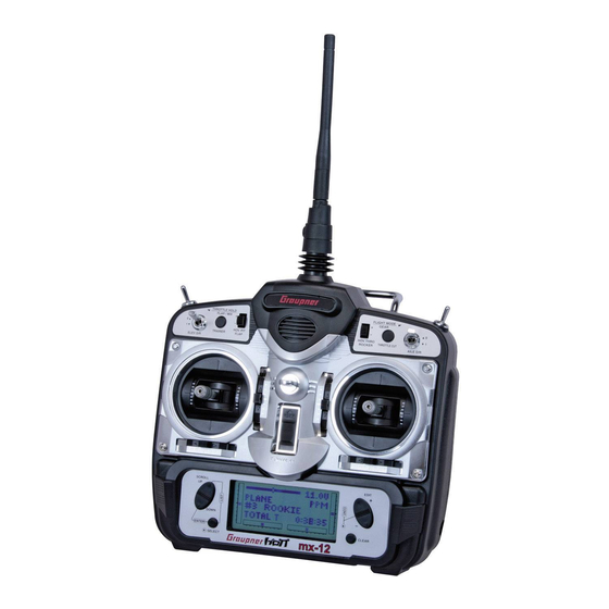
Page 9: Transmitter Description
TIGHTEN Elevator Rudder Stick Throttle Cut SW Neck strap attachment Elevator Trim An eyelet is provided on the face of the mx-12 transmit- Throttle (Pitch) ter that allows you to connect a Neck Strap. This hook Rudder Trim -Aileron Stick... -
Page 10: Transmitter Rear
If you don`t like this feeling, please follow the following Charging Jack instruction to change it. You will be required a posidrive for transmitter batteries (Graupner 8NH-1700 TX screwdriver and a pair of tweezers; Order No. 3414 included) Battery Cover 1. -
Page 11: Direct Servo Control
Turn the switch harness to the ON frequency, you can still adjust your aircraft and not Frequency notes The mx-12 can transmit in either Pulse Code Modulation position. interfere with the other pilot`s aircraft. (PCM) or Pulse Position Modulation (PPM, commonly... -
Page 12: Connections And Installations For Airplane
It is extremely important that your radio system be cor- CHANNEL (AUX1) rectly installed in your model. Here a few suggestions BATTERY installing your GRAUPNER equipment: 1. Wrap the receiver in protective foam rubber that GEAR is no less than 3/8 inch thick. Secure the foam to GEAR CHANNEL the receiver with #64 rubber bands. -
Page 13: For Helicopter
Connections and installations For Helicopter AUX1 PITCH SERVO BATTERY GYRO GEAR GEAR CHANNEL RUDD RUDDER SERVO SWITCH HARNESS ELEV ELEVATOR SERVO CHARGING JACK AILE RECEIVER ANTENNA AILERON SERVO R700 RECEIVER THRO THROTTLE SERVO WARNING Do not cut or fold the antenna! Connections and installations... -
Page 14: Key Input And Display
Key input and display; Alarm and error display Battery alarm and display When the transmitter voltage drops below 9.0 volts DC, the display flashes “BATT LOW“ and an alarm sounds. If you are flying when this occurs, land immediately. Up Key Increase Key Backup error display Down Key... -
Page 15: Input Mode And Function
Input mode and function Normal mode Advanced Digital Trim (A.D.T.) The mx-12 digital trims feature the Direct Access display Model Name function. While at the Normal display screen, if a trim Transmitter voltage (If there is) lever is moved, the screen will automatically change to display the graphic position for the trim being adjusted. -
Page 16: Function Mode
Function mode To enter the Function mode, switch the transmitter AIRPLANE HELICOPTER power switch to the On position. Press the Down and Select keys simultaneously, and the display will show 1. Dual Rate & EXPonential 13. Dual Rate & EXPonential the last active program. -
Page 17: System Mode
System mode To enter the System mode, press the Down and AIRPLANE HELICOPTER Select keys simultaneously, then turn the power switch to the ON position. The display will show the last active program. Pressing either the Up or Down key then 26. -
Page 18: List Mode
List mode To enter the Function List mode from the Function mode, HELICOPTER switch the transmitter power switch to the ON position. FUNCTION LIST 1 Press the Up und Select keys simultaneously. To scroll the functions, first press the Down and Select keys. FUNCTION LIST 1 FUNCTION LIST 2 FUNCTION LIST 2... -
Page 19: Function Mode Airplane
Dual-Rate switch for the both the 0 and 1 switch positions is 100%. channels of the mx-12 offer reversible servo direction. channel that you have selected. Either a 0 or a 1 will Exponential reduces the sensitivity in the middle portion... -
Page 20: Sub Trim
8. Access the D/R & EXP function by pressing the Select keys simultaneously. operation. The mx-12 offers travel adjust for all six Down key. 3. Press either the Up or Down key until SUB TRIM channels. -
Page 21: Elevator To Flap Mixing
Function mode AIRPLANE Elevator to flap mixing; Aileron to rudder mixing highlighted. Up key. RIGHT FWD: Gear SW Forward side On 5. Move the appropriate control stick (lever, switch, 8. Access the AIL RUD MIX Mixing function by pres- RIGHT REA: Gear SW Rear etc.) to the right or left of center to the direction of... -
Page 22: Throttle Cut Switch
Function mode AIRPLANE Throttle Cut switch; Flap System Throttle Cut switch 5. Access the AIL RUD MIX function by pressing the Go to Throttle cut Change value/Select menu This function assigns the Throttle Cut switch to the push Up key. switch Go to Ele... -
Page 23: Differential Aileron Mixing
Programmable Mixing (1~4) the ailerons (one on each). In the Function Mode, use The mx-12 offers four programmable mixes to be used the UP or DN key to select Differential Aileron Mixing for any number of different purposes. This function al- and access by pressing the UP and DN keys simulta- lows mixing any one channel to any other channel. -
Page 24: Fail Safe
5. When using the servo setting position, move the Mixing Operation and Switches ning to the broadcast signal of your mx-12 transmitter. corresponding control stick to the position where you Each mixing program can be turned on and off by a want the servo if the radio enters into the fail safe lever or switch. -
Page 25: Servo Travel Screen
Function mode AIRPLANE Servo Travel Screen Up key. Indicator 3: Elevator 8. Access the MIXING FUNCTIONS function by pres- Indicator 4: Rudder sing the Up key. Indicator 5: Gear 9. Exit the FAIL SAFE function by pressing the Down Indicator 6: Flap and Select keys simultaneously. -
Page 26: Function Mode Helicopter
The Reverse Switch function is an electronic means of reversing the throw of a given channel (servo). All six 2. Access the Function mode by pressing the Down channels of the mx-12 offer reversible servo direction. Go to Reversing Change channel SW menu and Select keys simultaneously. -
Page 27: Sub Trim
EL 3: Elevator RU 4: Rudder tion. The mx-12 offers travel adjust for all six channels. position to be adjusted GE 5: Gear The Travel Adjust range is from 0-150% (0 degrees to 6. -
Page 28: Ccpm Swashplate Mixing
The CCPM Swashplate Mixing Function (Cyclic 120° CCPM or 180° CCPM appears in the middle Type Function will not appear on the LCD screen in Collective Pitch Mixing) of the mx-12 is designed to be left portion of the LCD. this section. -
Page 29: Throttle Cut Switch
Function mode HELICOPTER Throttle Cut Switch; Throttle Hold Ch6 = Pitch Throttle cut function. 3 servo (120°) Note: Pressing the Clear key will Inhibit the Throttle Ch2 = Aileron Cut, turning it off until it has been reactivated. Ch2 = Elevator 4. -
Page 30: Throttle Curves
Note: In each curve, the factory setting indicates INH curve points The mx-12 offers two (2) separate throttle curves with for points 1 and 3. These values are 25% and The transmitter is factory preset to the throttle curve as five adjustable points per curve. -
Page 31: Pitch Curves
Function mode HELICOPTER Pitch Curves trim lever has no effect on positions 1 or throttle hold. Hovering Throttle Knob Go to Revolution Operating Range (Parallel) Output Value Mixing menu Change Value/Switch Note: Making changes to the throttle trim lever does selection Go to Throttle Curve not change the input values for any of the points... - Page 32 Function mode HELICOPTER press the Up key once again until “H“ is displayed, Throttle Pitch and repeat steps 4 and 5. 8. Access the REVO MX function by pressing the Up key. 9. Access the THROTTLE CURVE function by pres- sing the Down key.
-
Page 33: Revolution Mixing (Non-Heading Lock Gyro Only)
5. Press the (+) key to increase the right tail compen- Mix number 1 is of the standard variety, in that the digital the tail rotor pitch at the same time. The mx-12 offers sation or press the (-) key to increase the left com-... -
Page 34: Fail Safe
8. While holding the master stick in the direction you pears in the upper portion of the LCD screen. the mx-12 transmitter in PCM modulations. This function want to mix, press the (+) or (-) keys to increase or 3. Use the Select key to highlight the servo function to is designed to help minimize damage to your aircraft decrease the mixing value for the slave channel. -
Page 35: Servo Travel Screen
Function mode HELICOPTER Servo Travel Screen 6. Repeat steps 4 and 5 until all six controls have been 3. Move the sticks. The indicators correspond to the set. following: 7. Access the SERVO TRAVEL screen by pressing the Indicator 1: Throttle Up key. -
Page 36: System Mode Model Selection
8. Press the Down and Select keys simultaneously to Model Name Entry exit the MODEL NAME function. The mx-12 allows on 8-digit name to be input for each of the ten models available. The current model will be Selectable character: Model Name (If programmed) displayed in the Normal display. -
Page 37: Model Type Selection
8. Press the Down and Select keys simultaneously 4. Next, press the Clear key. The current model will The mx-12 is capable of performing as a helicopter or to exit the MODEL TYPE function. then be copied to the selected model. -
Page 38: Modulation Selection
The Modulation Selection function enables your mx-12 Fixed-wing stick mode: rudder and throttle / airbrake for fixed-wing models; roll, to transmit to a variety of GRAUPNER receivers. You MODE 1 (Throttle at right stick) MODE 2 (Throttle at left stick) -
Page 39: Trainer Function
Pilot Link + Slave: - This mode is used only wehen the 7. To exit the TRAINER function, press the Down and mx-12 is being used as a slave transmitter and the other Select keys simultaneously. Master transmitter has a Pilot Link program active. By... -
Page 40: Switch Select
Switch Select COM AILE ELEV D/R The mx-12 allows the several options to be programmed In this mode the aileron, elevator and rudder dual rates The flap channel operates from the elevator dual rate for the dual rate, gear and flap switches (flight mode are combined on the AILE D/R switch. -
Page 41: Wing Type Selection
System Mode Wing Type Selection ELEV D/R Go to Model Select menu The gear channel operates from the elevator dual rate Turn selected type on or off Go to Switch Select switch. menu INHIBIT Return to Default mode The gear channel is inhibited and is centered making it Definition of Wing Types useful as a slave channel for mixing. - Page 42 Elevon Wing Mixing is available as an option with your 11. To exit the WING TYPE function, press the Down not move as described above, use the Servo Rever- mx-12. This style of aircraft also employs two wing and Select keys simultaneously. System Mode...
- Page 43 System Mode V-Tail Type Selection in this manual. V-tail mixing is available as an option with your mx-12. 7. Once the servos direction has been set, adjust their V-tail equipped aircraft require two servos. travel direction, travel adjust, dual rates, sub-trim.
-
Page 44: Swashplate Selection
System Mode Swashplate Type Selection Swashplate Type Selection Switch function, press the Down key. The Swashplate Mixing function enables the mx-12 5. Press the Up key to access the MODEL SELECT system to operate many different types of swashplate function. -
Page 45: Approved Operating Frequencies
Approved operating frequencies, available crystals, frequency pennants situation in your own country. It is prohibited to operate a radio control system on any frequency and channel other than those listed. Approved operating frequencies... -
Page 46: Approval Certificate Conformity
Approval certificate Conformity Approval/Conformity... -
Page 47: Guarantee Certificate
Sur ce produit nous accordons une garantie de mois Servicestellen / Service / Service après-vente Die Fa. Graupner GmbH & Co. KG, Henriettenstraße 94- Cette garantie ne remet pas en cause les droits et 96, 73230 Kirchheim/Teck gewährt ab dem Kaufdatum prétentions légaux du consommateur.
Need help?
Do you have a question about the MX-12 and is the answer not in the manual?
Questions and answers