
Related Manuals for GRAUPNER mx-16 HOTT


Summary of Contents for GRAUPNER mx-16 HOTT
- Page 1 33116.mx-16 HoTT.2.gb H O P P I N G T E L E M E T R Y T R A N S M I S S I O N mx-16 Programming Manual...
-
Page 2: Table Of Contents
Contents General Information Digital trims ..............40 Examples............. 111 Fixed-wing model aircraft..........42 “Swashplate mixers” ..........112 Safety Notes ..............3 Receiver socket sequence ....... 43/44 Safety notes and handling instructions relating “Servo display” ............113 Model helicopters ............46 to Nickel-Metal-Hydride rechargeable batteries .... -
Page 3: Safety Notes
fi bre components, servos, electric motors, fuel pumps, matching Graupner connectors of the same design with pectedly, with the result that parts may fl y off at great cabling of all kinds, etc.. - Page 4 Safety Notes any other installed equipment in the model, but in an Ensure that no metal parts are able to rub against each from other transmitters and any interference, and may easily accessible position. Under no circumstances al- other, e. g. when controls are operated, when parts respond.
- Page 5 Keep the receiving system an adequate distance away tant to avoid short-circuits. Do this by fi rst connecting the Refer to the main Graupner FS catalogue or the Internet from the ignition system. banana plugs on the charge lead to the charger, taking website at www.graupner.de for more information on...
- Page 6 Liability exclusion / Compensation effects on the system’s electrical characteristics and It is not possible for Graupner to ensure that the user radiation pattern. observes the installation and operation instructions, and •...
- Page 7 For your notes...
-
Page 8: Safety Notes And Handling Instructions Relating To Nickel-Metal-Hydride Rechargeable Batteries
Safety notes and handling instructions relating to Nickel-Metal-Hydride rechargeable batteries As with all sophisticated technical products, it is vitally charge. Never exceed the maximum fast-charge cur- with every charge / discharge process. Stored batteries important that you observe the following safety notes rent specifi... - Page 9 NiCd and tion points, Graupner retail outlets, and any other shop NiMH batteries. If you are not sure about this, please where dry and rechargeable batteries of the same type refer to the operating instructions supplied with your are sold.
-
Page 10: Foreword
This (air-) space available. The simple fact that no frequency cess with your mx-16 HoTT - a radio control system of means that the transmitter requires no additional mod- control procedure is necessary equates to an enormous the latest generation. -
Page 11: Description Of Radio Control Set
Computer System Eight-channel radio control set with Graupner HoTT 2.4 GHz technology (Hopping Telemetry Transmission) • Micro-computer radio control system exploiting the latest Graupner HoTT 2.4 GHz technology • Bi-directional communication between transmitter and receiver • Five different languages German and English;... - Page 12 Computer System Eight-channel radio control set with Graupner HoTT 2.4 GHz technology (Hopping Telemetry Transmission) specifi c programming and set-up parameters linkages (1 servo, 2 servo, 3sv(2roll), 3sv(140°), servos only) 3sv(2nick (pitch-axis)), 4 SV (90°)) • Seven switches (two three-way switches, three two- •...
-
Page 13: Recommended Battery Chargers
Description For details of additional battery chargers, and details of the chargers 2498.4FBEC 4NH-2000 RX RTU, fl at-pack listed here, please refer to the main Graupner FS catalogue, or our 33800 HoTT transmitter aerial Internet site at www.graupner.de. Description of radio control set... -
Page 14: Transmitter Power Supply
Transmitter power supply 200 mA. Removing the transmitter battery The mx-16 HoTT transmitter is fi tted as standard with The transmitter must be switched “OFF” for the whole To remove the transmitter battery, fi rst disengage the period of the charge process. Never switch on the... - Page 15 Battery timer, bottom left corner of the screen This timer displays the cumulative operating time of the transmitter since the last time the transmitter battery was charged. This timer is automatically reset to “0:00” when the transmitter detects that the voltage of the transmitter battery is signifi...
-
Page 16: Receiver Power Supply
Note: Henriettenstr. 94 - 96 wish to charge the standard Ni-MH battery using an Please refer to the main Graupner FS catalogue or visit automatic charger designed for Ni-Cd batteries. D-73230 Kirchheim unter Teck the Internet site at www.graupner.de for full details of •... -
Page 17: Adjusting The Stick Length
Graupner Service Centre to carry out the work for you. Hold the bottom half of the knurled grip fi rmly, and C A U T I O N... -
Page 18: Changing The Stick Mode
Operating Notes Converting the dual-axis stick units Self-centring action Either or both sticks can be converted from self-neutral- Folding aerial ising to non self-neutralising action: start by opening the transmitter as described on the previous page. If you wish to change the standard stick unit arrange- ment, start by locating the screw on the left-hand stick unit shown circled in white in the photo below. - Page 19 Brake spring and ratchet Stick centring force You can alter the braking force of the stick by adjusting The centring force of the sticks is also variable to suit the outer of the two screws circled in white in the next your preference.
-
Page 20: Description Of Transmitter
Attaching the transmitter neckstrap Central Status LED You will fi nd a strap lug mounted in the centre of the front face of the mx-16 HoTT transmitter, as shown in Aerial with folding / rotating base Neckstrap lug the drawing on the right. This lug is positioned in such a... -
Page 21: Rear Of Transmitter
For connecting the optional Smart-Box, Order No. 33700. Transmitter battery For more details about the Smart-Box please refer to the charge socket Battery compartment cover main Graupner FS catalogue, or refer to that product on the Internet at www.graupner.de. Case screw Case screw Description of transmitter... -
Page 22: Dsc (Direct Servo Control)
Data storage Direct Servo Control Card slot micro-SD and micro-SDHC When you switch off the mx-16 HoTT transmitter and The original function of this socket was for “Direct Servo PUPIL stop 0:00 Control”, and that’s why the abbreviation is still in use. - Page 23 PC stop 0:00 or laptop. The data can subsequently be analysed on a 0:00 compatible PC using the PC program available on the Download page for the transmitter at www.graupner.de. 5.2V HoTT 3:33h 5.5V Importing voice fi les As mentioned in the “Headphone socket”...
-
Page 24: Screen And Keypad
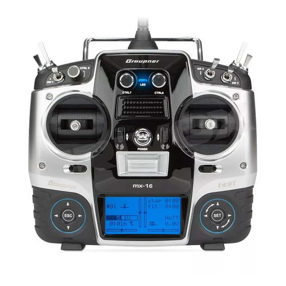
Screen and keypad Visual display of the trim lever positions; alternatively - if rota- ry controls CTRL 7 … 9 are operated - display of the current settings of these two controls Model type display Model name See page 28 for possible warnings (fi... -
Page 25: Operating The "Data Terminal
Operating the “Data Terminal” Input buttons ESC, SET, CLEAR, Short-Cuts symbols On-screen telemetry symbols Buttons to the right of the screen You can call up particular menus or options directly us- ing the following button combinations: The active model memory is not yet “bound” •... -
Page 26: Language Selection, Screen Contrast
Activate the value fi eld by pressing the central but- These voice messages are collected in a voice package of the mx-16 HoTT transmitter can be accessed from ton of the right-hand touch-key: and stored in the transmitter’s internal memory, but they... - Page 27 Changing the language HIDDEN MODE SD-CARD CONTRAST Use the arrow buttons of the left or right-hand touch-key INSERT LANGUAGE ENGLISH to move to the “VOICE” line: VOICE ENGLISH HIDDEN MODE … appears, then there is no memory card in the card CONTRAST 22/100% slot, or the card cannot be read.
-
Page 28: On-Screen Warnings
Warnings On-screen function fi elds SEL, STO, SYM, ASY, Warnings The bottom line of the screen displays function fi elds CAN‘T which vary according to the menu selected. RECEIVE “Binding not present” No bound receiver in range. DATA No receiver is bound to the BIND N/A currently active model mem- ory. -
Page 29: Position Indicator, Rotary Controls Ctrl 7 + 8
CTRL 7 + 8 on the centre console, a small symbol ap- the touch-keys, and with them access to all the set-up options, from the base display of the mx-16 HoTT pears to the right of the two vertical position indicators:... -
Page 30: Using The Transmitter For The Fi Rst Time
Using the transmitter for the fi rst time Preliminary notes regarding the mx-16 HoTT transmitter For more information please visit our Internet site at www.graupner.de Preliminary notes Within this period you can switch off the RF signal if At the right of the same line a display in the same format required by moving the black fi... - Page 31 Universal / EUROPE mode! • You can operate up to eight servos using the mx-16 HoTT transmitter and the receiver sup- plied in the set, which is already bound to the transmitter. However, in the interest of maximum possi- ble fl...
-
Page 32: Using The Receiver For The Fi Rst Time
Receiving system about one second. socket is defi ned by the radio control system, and may The mx-16 HoTT radio control set includes a GR-16 differ according to the make and type. Firmware update In the case of Graupner radio control systems the 2.4 GHz bi-directional receiver which is suitable for con-... - Page 33 connect its power supply; release the button again. If the reset is carried out with the transmitter switched off, or if the receiver is not already bound, the receiver LED fl ashes red slowly after about two or three sec- onds;...
-
Page 34: Installation Notes
The sequence in which the servos are connected to the Regardless of which Graupner receiving system you are model: receiver is dictated by the model type. Please see the using, the procedure is always the same: Wrap the receiver in foam rubber at least 6 mm thick. -
Page 35: Receiving System Power Supply
Nanophosphate® pack presents no problems to tends to produce a creeping increase in transfer resist- connected to the receiver. Graupner HoTT receivers, nor to those servos, speed ance. Auxiliary function controllers, gyros, etc. which are expressly approved for It is also true that even small servos, such as the Graup- use at these higher voltages. - Page 36 Nanophosphate® types. The comparatively high nominal voltage of 7.4 Volt of a two-cell LiPo pack presents no problems to Graupner HoTT receivers, nor to those servos, speed controllers, gyros, etc. which are expressly approved for use at these higher voltages.
- Page 37 For your notes...
-
Page 38: Defi Nition Of Terms
Defi nition of terms Control functions, transmitter controls, function inputs, control channels, mixers, switches, control switches To make it easier for you to understand the mx-16 • The switches SW 4/5 and 6/7, and CTRL 9 and 10 affect multiple servos at the branching point of the mixer HoTT manual, the following section contains defi... -
Page 39: Switch And Transmitter Control Assignment
The mx-16 For both model types the mx-16 HoTT transmitter’s and assign the switch again, this time with the switch HoTT allows you to assign several functions to a single direction you prefer. -
Page 40: Digital Trims
Digital trims Description of function, and Ch 1 cut-off trim Digital trims with visual and audible indicators 1. Fixed-wing models 2. Model helicopters The Ch 1 trim features a special cut-off trim which is In helicopter mode the Ch 1 trim has another feature in Both the dual-axis stick units are fi... - Page 41 For your notes...
-
Page 42: Fixed-Wing Model Aircraft
Fixed-wing model aircraft This program provides convenient support for normal tail, you need to select the tail type “V-tail” in the “Basic “Dual Rate” and “Exponential” can be programmed model aircraft with up to two aileron servos and two fl ap settings”... -
Page 43: Receiver Socket Sequence
Receiver socket assignment for models with up to two ailerons and two fl aps, plus “normal” tail type, V-tail, Installation notes and two elevator servos (3 + 8) The servos MUST be connected to the receiver outputs in the following order: Outputs not required are simply left vacant. - Page 44 Receiver socket assignment for models of the “Delta / Flying wing” type, with up to two fl aps As there are several possible combinations of servo orientation and control surface linkage, you may fi nd that the direction of rotation of one or more servos is incor- rect.
- Page 45 For your notes...
-
Page 46: Model Helicopters
The helicopter program of the mx-16 HoTT can cope the “Helicopter mixers” menu provides fi ve-point curves the motor in any fl ight phase. By default the proportional with all current model helicopters equipped with 1 …... -
Page 47: Receiver Socket Sequence
Note for modellers upgrading from earlier Graupner menu described on page 64 / 65. Installation notes systems: All menus which are relevant to model helicopters are The servos MUST be connected to the receiver Compared with the previous receiver channel sequence, marked with a “helicopter”... -
Page 48: Program Descriptions Setting Up A New Model Memory
Detailed description of programming Reserving a new memory If you have already read through the manual to this => select model point, you will undoubtedly have made your fi rst attempt free clear model => at programming the system already. Even so, it is impor- free copy mod–>mod =>... - Page 49 responding symbol, then again press the central directly to the corresponding option. For more de- ready been entered in the “Basic settings” menu button of the right-hand touch-key briefl y in confi rmation. tailed information on binding a receiver please refer (pages 56 and 64), together with an indicator that the This initialises the selected model type for the model to pages 61 and 70.
- Page 50 max. 8 remain steadfastly at their centre position. If you set up a new model helicopter, servo 6 may also re- spond to some extent to the controls - depending on the position of the throttle limiter CTRL 6. For both model types this situation only changes once you have carried out the appropriate assignments in the “Transmitter control settings”...
- Page 51 For your notes...
-
Page 52: Model Memories
Model memories Calling up a model, erasing a model, copying model model The section on pages 24 and 25 explains the basic select model clear model method of using the buttons, while the previous two => => select model select model double-pages explains how to move to the Multi-function =>... - Page 53 Caution: select the target memory using the arrow buttons Export to SD The erasure process is irrevocable. All data in the of the left or right-hand touch-key, and confi rm your Use the arrow buttons of the left or right-hand selected model memory is reset to the factory choice with SET.
- Page 54 copied to the SD card. => select model model Notes: clear model => copy mod–>mod => ULTIMATE • If the warning … => => free expor t to SD SD-CARD => => impor t ? impor t from SD INSERT Use the arrow buttons of the left or right-hand You can interrupt the process with NO;...
- Page 55 For your notes...
-
Page 56: Base Settings" (Model) Fixed-Wing Model Aircraft
Base settings Basic model-specifi c settings for fi xed-wing model aircraft Before you start programming specifi c parameters, in the name by touching one of the arrow buttons the Select fi eld framed: some basic settings must be entered which apply only of the right-hand touch-key, or its central button. - Page 57 The throttle warning message “Throttle too • Depending on your choice in this menu, the Ch 1 trim cut off high”, see page 28, and the option “cut off” acts “normally” (over the full control travel), or just Note: are activated. In the “Wing mixer” menu the at the idle end of the range, i.
- Page 58 ble range of the throttle stick using the switch which has tail type with two elevator servos. When the eleva- tor stick is moved, the servo connected yet to be assigned in the right-hand column. to receiver output 8 moves in parallel with mod name GRAUBELE However, if you want to set an individual threshold after...
- Page 59 here. The software provides a maximum of twelve the stopwatch. motor at C1 idle re. ready-made mixers for up to two aileron servos and two The method of assigning a physical switch or a control cut off –125% +100% camber-changing fl ap servos. switch is described on page 39.
- Page 60 For maximum fl exibility in terms of receiver socket switches assigned to phase 3 or 4 is also closed, or (CLEAR), once you have halted the timer. assignment, the mx-16 HoTT software provides the phase 3, if the switches assigned to phases 3 and 4 Note: means to swap over the servo outputs 1 to max.
-
Page 61: Binding Receivers
4 landing Graupner HoTT receivers have to be “instructed” to key - refers exclusively to the “control channels”, i. e. the receiv out communicate exclusively with a particular model (i. e. outputs are NOT swapped over. -
Page 62: Range-Checking
Contact your nearest tons of the left or right-hand touch-key to move rx bind Service Centre of Graupner GmbH & Co. KG. to the “Test range” line, and initiate range-check mode by briefl y pressing the central button of the right- Carry out the range-check before every fl... - Page 63 phase 4 landing receiv out rx bind range test 99sec RF transmit Now you can use the right-hand arrow buttons to switch between OFF and ON. Touch the central button of the right-hand touch-key again to conclude the input. Program description: base settings - fi xed-wing model...
-
Page 64: Model Helicopter
Base settings Basic model-specifi c settings for model helicopters Before you start programming specifi c parameters, tons of the right-hand touch button, or its central is now framed: some basic settings must be entered which apply only button, to move to the next position in the name, at mod name STARLET to the currently active model memory. - Page 65 As part of the auto-rotation set-up procedure of the roll servos (left and right). For collective mx-16 HoTT transmitter’s Helicopter program there is pitch control all three servos move the the option to defi ne a “motor OFF” position for the throt- swashplate axially.
- Page 66 default settings are -100% for the “Motor OFF” position rotation of the main rotor using the arrow buttons of the mod name STARLET of the throttle servo and +150% for the throttle curve: right-hand touch-key, after briefl y pressing the central stick mode button: swashplate...
- Page 67 Collective pitch min. “rear”: minimum collective pitch when the collective … using the switch symbol at the bottom right-hand pitch stick (Ch 1) is “back” (towards you). side of the screen. The assigned switch starts both tim- stick mode ers, and also halts the stopwatch. Simultaneously pressing the buttons of swashplate...
- Page 68 off the time elapsed after reaching zero. To make this swashplate 3sv(2rol) rotor direct right clear, the over-run time is shown highlighted (black cut off –125% +100% 1 pitch min rear background). rotor direct right timer 10:01 pitch min rear phase 2 hover –––...
- Page 69 You can now assign phase 3 speed In the helicopter program of the mx-16 HoTT the a switch to the phase as described on page 39. We autorotat. outputs for one collective pitch servo and the throttle...
-
Page 70: Binding Receivers
At the same time the word When operating the system, please note that only Carry out the range-check of the Graupner HoTT system “BINDING” starts fl ashing in the frame of the “rx bind” the receiver which was bound last will establish a in accordance with the following instructions. - Page 71 100% the case, do not use the system. Contact to the “Test range” line, and initiate range-check your nearest Graupner Service Centre. Now you can use the right-hand arrow buttons to switch mode by briefl y pressing the central button of Carry out a range-check before every fl...
-
Page 72: Servo Settings
Servo settings Servo direction, centre, travel connected, assuming that these have not been swapped Column 3 “Centre” 100% 100% over. This means that changing the stick mode does not The facility to offset the servo travel centre is intended 100% 100% affect the numbering of the servos. - Page 73 Column 4 “- Servo travel +” directly by a stick channel, or by means of any type of mixer function. In this column you can adjust servo travel symmetrically or asymmetrically (different each side of neutral). The adjustment range is 0 … 150% of normal servo travel. The reference point for the set values is the setting in the “Centre”...
-
Page 74: Transmitter Control Settings
In addition to the two dual-axis stick units for the control you like, and that you are not required deliberately to functions 1 to 4, the mx-16 HoTT is fi tted as standard “program away” the transmitter controls which are not Column 2 “Assigning transmitter controls and... - Page 75 will fi nd in the “Transmitter control settings” menu as Column 3 “-Travel+” touch-key to alter the values: “Control 9” and “Control 10”, provide a centre position in In this column the transmitter control can be adjusted +100% +100% addition to the two end-points. symmetrically or asymmetrically, i.
-
Page 76: Model Helicopter
This may seem rather inconvenient at fi rst sight, but key, and the corresponding input fi eld is highlighted. functions 1 to 4, the mx-16 HoTT is fi tted as standard it is the only way to ensure that you can select any of... - Page 77 or 9). Note that the rotary proportional controls are not +100% +100% +100% +100% detected until they have moved a few “ratchet clicks”, i. e. free +100% +100% free +100% +100% they need to be operated for slightly longer. If the travel ctrl 7 +100% +100% ctrl 7...
- Page 78 Important: “Throttle” „Gyr“ In contrast to servo travel adjustments, changing the +100% +100% +100% +100% transmitter travel setting affects all mixer and coupling free +100% +100% free +100% +100% inputs derived from it, i. e. in the fi nal analysis all the ctrl 7 +100% +100%...
-
Page 79: Throttle Limit Function
You can call up the “Servo display” menu to check the off an electric motor directly. At the other extreme, the fl exible with the mx-16 HoTT program, and can be throttle servo or speed controller can, of course, only infl... - Page 80 To complete this basic set-up you still have to adjust the Last idle position Current trim position idle trim range to coincide with point “1” of the throttle Throttle limit cont stop curve. This is accomplished by setting point “1” of the input “Ch 1 throttle”...
- Page 81 For your notes...
-
Page 82: Fixed-Wing Model Aircraft
D/R Expo Switchable control characteristics for aileron, elevator and rudder Use the arrow buttons of the left or right-hand touch- tions (aileron, elevator and rudder), without forfeiting “Base settings” menu (see page 60), then this appears key to leaf through to the “D/R Expo” menu point of the full travel at the end-points of stick movement. - Page 83 … and assign a physical switch as described in the sec- which indicates the direction of operation when you Combined Dual Rate and Expo tion “Assigning switches and control switches” on page move the switch. If you enter values for both Dual Rates and Expo, the 39.
-
Page 84: Model Helicopter
D/R Expo Switchable control characteristics for roll, pitch-axis and tail rotor Another application for exponential is to improve the the desired line “Roll”, “Pitch” or “Tail” using the arrow roll 100% ––– linearity of rotary-output servos, which are the standard buttons of the left or right-hand touch-key. - Page 85 edge of the screen, and set the values for each of the tion. Combined Dual Rate and Expo two switch positions separately in the highlighted fi eld Select the right-hand column, marked with EXPO at If you enter values for both Dual Rates and Expo, the using the arrow buttons of the right-hand the bottom edge of the screen, in order to change the...
-
Page 86: Phase Trim" (Fi Xed-Wing)
Phase trim Flight phase-specifi c trims for fl aps, ailerons and elevator If you have not assigned a switch to phases 2, 3 and 4 If you wish to enter values other than “0”, e. g. to have • dist(ance) in the “Basic settings”... - Page 87 Note: P H A S E T R I M In this menu you will have at least one control function normal (ELE), and a maximum of three functions (ELE, AIL and takeoff FLA), available for phase-specifi c trim settings, depend- speed ing on the settings you have entered in the “Aileron / thermal...
-
Page 88: What Is A Mixer
“No (motor)” and “2AIL 2FL”). Left rudder / elevator The mx-16 HoTT transmitter’s program contains a se- V-tail mixer ries of pre-programmed coupling functions, and all you Right rudder / elevator have to do is set the mixer ratios and (optionally) assign a switch. - Page 89 Notes: ing fl aps are defi ned; this is intentional, as it elimi- end-point of the transmitter control the full mixer value is nates the danger of errors when a fl ap command is applied. • There are various alternative methods of positioning given.
- Page 90 have to be “designed in” when the model is built, and the For aerobatic fl ying it is necessary to set low absolute Note: degree of differential cannot be altered subsequently. differential values, to ensure that the model rotates Negative values are not usually necessary if the correct In any case signifi...
- Page 91 fl aps (Aileron fl ap) brak elev (Airbrake elevator) brak fl ap (Airbrake fl ap) This mixer feeds a variable amount of the aileron signal Extending any form of airbrakes usually generates an When you operate the brake function (Ch 1 stick), both into the fl...
- Page 92 servos move together for the landing approach; the This inter-action between the fl aps, ailerons and elevator part of the elevator signal to the fl ap servos. The mixer mixer ratio can be set to any value in the range -150% is used to control the glide angle on the landing ap- direction must be set so that the fl...
- Page 93 When the camber-changing fl aps are lowered, either Note: right-hand touch-key (CLEAR) resets an altered value using “Phase trim” or by means of a transmitter control If you assign a transmitter control to inputs 5 and 6 in to 0%. assigned to input “6”, a pitch trim change (up or down) the “Transmitter control settings”...
-
Page 94: Heli Mixer
Helicopter mixers Flight phase-specifi c mixers for collective pitch, throttle and tail rotor In the “Basic settings” menu a method of switching of the following names: (CLEAR). fl ight phases can be activated by assigning the appropri- • hover The name of the currently selected fl ight phase is ate switches to “Phase 2”, “Phase 3”... - Page 95 the right-hand touch-key (CLEAR) resets an altered The programming procedure in detail However, the optional points “2” and “4” can also be value to the default value. activated. In the next example we activate point “2” at The throttle / collective pitch stick can now be used to -50% …...
- Page 96 Helicopter with glow engine or electric motor and in the mx-16 HoTT program is more fl exible, and can STANDARD SPEED CONTROLLER be fi ne-tuned more accurately, than the “idle-up” system...
- Page 97 Typical throttle curves for different fl ight phases: in the “Lim” line of the “Transmitter control settings” contrast to the usual socket sequence - and the throttle menu. However, the throttle curve itself has to be fi ne- curve adjusted so that it can simply assume the role of +100% +100% +100%...
- Page 98 tail rotor (static torque compensation) tems. tail We recommend that you set up switchable fl ight phases tail for this, and set different gain settings for each phase in input the “Gyro” line; values between -125% and +125% are output input possible.
- Page 99 • The mechanical control system should be as free- gyro In the mx-16 HoTT transmitter a software function has moving and accurate (slop-free) as possible. inp8 the effect of limiting the overall swashplate travel, i. e. the •...
-
Page 100: Setting Up Throttle And Collective Pitch Curves
Reference point 1 of the throttle curve defi nes the throttle In the mx-16 HoTT program the trim lever of control help you with the basic set-up. setting when the helicopter is in a descent, but without function 1 only affects the throttle servo, i. - Page 101 of this manual for a full explanation of the digital trims. b) Rotational speed too low already fully open and no further power increase is pos- +100% sible (this assumes that the motor is correctly adjusted), Remedy: on the “Collective Around the mid-point of the collective pitch stick the pitch”...
- Page 102 Important fi nal notes in premature wear of the clutch and gear train. The main +100% rotor blades are generally free to swivel, and they may Before you start the motor, check carefully that the throt- be unable to keep pace with such swift acceleration, in tle limiter is completely closed, so that the throttle can This diagram only shows the which case they might respond by swinging far out of...
- Page 103 For your notes...
-
Page 104: Auto-Rotation Setting
Helicopter mixers Auto-rotation settings Auto-rotation allows full-size and model helicopters to cilities which are designed to help you fl y your helicopter tive pitch minimum value at Point 1 to ensure that your land safely in a crisis, i. e. if the power plant should fail. in its unpowered state. - Page 105 For practice, then, you should set the value in this line Depending on the friction and running resistance of the so that the motor runs at a reliable idle during auto- gearbox, you may fi nd that the fuselage still yaws slightly rotation, but without the clutch engaging, so that you in an auto-rotation descent.
-
Page 106: General Notes Re. Freely Programmable Mixers
In addition to the pre-programmed mixers mentioned channel which is programmed as the mixer output. D/R expo phase trim above, the mx-16 HoTT offers three freely program- • … the neutral point, which is also termed the wing mixer... -
Page 107: Free Mixers
Free mixers Linear mixers Regardless of the selected model type, three linear mix- screen, touch the central button of the right- control functions 5 … 8 for a fi xed-wing model, or 5, 7 ers are available for each of the twenty model memories, hand touch-key again, and assign a switch if desired, and 8 for a model helicopter, in the “Transmitter control with the additional possibility of setting up non-linear... - Page 108 Erasing mixers Additional special features of free mixers • Model helicopters: If you set up a mixer whose input is the same as its Depending on the type of helicopter, up to four ser- If you need to erase a mixer that you have already output, e.
- Page 109 Mixer ratios and mixer neutral point “Transmitter control settings” menu MIX1 Now that we have explained the wide-ranging nature of free +100% +100% the mixer functions, we can move on to the method of ctrl 7 +100% +100% programming linear and non-linear mixer curves. free +100% +100% For each of the three available mixers the mixer curves...
- Page 110 Notes: need to be established through a fl ight testing pro- MIX1 gramme. • If you wish, you can move the offset value back to centre or otherwise adjust it as follows: select SEL tr v MIX1 using the arrow button of the left or right-hand offs touch-key, followed by briefl...
-
Page 111: Examples
the left and right sides. tral button of the right-hand touch-key. MIX1 According to the travel setting selected in the “Trans- Examples: mitter control settings” menu and the switch posi- tr v +20% +20% The switch SW3 has already been assigned to con- tion, the offset value now jumps to +X% or -X%, e. -
Page 112: Swashplate Mixers
Swashplate mixers Collective pitch, roll and pitch-axis mixers on all the collective pitch servos you are using, with- the proper manner, then the fi rst step is to change the SP – MIXER out affecting the throttle servo. mixer directions (“+” or “-”), before you attempt to correct ptch +61% the directions of servo rotation. -
Page 113: Servo Display
Servo display Use the arrow buttons of the left or right-hand touch-key this does not relieve you of the need to check all your to leaf through to the “Servo display” menu point of the programming steps carefully on the model before oper- multi-function menu: ating it for the fi... -
Page 114: Basic Settings
In this menu you can enter basic settings which are Batt war ning 4.7v You can adjust the contrast of the mx-16 HoTT’s in- specifi c to the transmitter. Touch Sense tegral screen to optimise its legibility in varying weather... - Page 115 remains on when you switch the transmitter on, and Voice volume stop 0:00 after the last button-press. 0:00 Touch Sense The available values are “unlimited” “30 s”, 60 s” and Contrast “120 s”. 5.2V HoTT Display light unlim Simultaneously pressing the arrow buttons 3:33h 5.5V RF Country...
-
Page 116: Fail-Safe
Fail-Safe transmitter to receiver. The receiver outputs 1 … 8 can and 1 s). FAIL SAFE optionally … Simultaneously pressing the arrow buttons maintain (“hold”) their current position: of the right-hand touch-key (CLEAR) resets the high- lighted fi eld to the default value of 0.75 s. If interference should occur, all servos programmed hold to “hold”... -
Page 117: Telemetry
If you register your product under http://www.graupner. when carrying out the programming. Do not make any alterations unless the motor is de/en/service/product_registration you will automatically switched off and the fl... -
Page 118: Setting & Data View
Basic menu operation R-VOLT :05.0V DATA In general terms the “Telemetry” menu is operated just L.R-VOLT:04.5V like the other menus of the mx-16 HoTT transmitter. SENSOR1 :00.0V 00°C SENSOR2 :00.0V 00°C The few differences are described below: … appears instead of the desired sub-menu when you... - Page 119 When operating a model this value should not fall below which the radio control system went into Fail-Safe mode. L.R-VOLT Lowest receiver operating voltage -90 dBm; if it does, reduce the distance between the since the last power-on, in Volt Operating voltage (R-VOLT) pilot and the model.
- Page 120 RX SERVO channel (e. g. 01). The following parameters always (control surface travel) for the servo connected to the refer to the channel which you set at this point: control channel selected in the “OUTPUT CH” line. The RX SERVO value is set separately for each side of centre.
- Page 121 A similar alternative, albeit slightly more diffi cult to ac- functions of the mx-16 HoTT transmitter can be cess, is to use the “FAIL-SAFE ALL” option described on Assign one and the same INPUT CH (control chan- shared out between several receivers if necessary, or the next double-page.
- Page 122 lay time” set in the “DELAY” line. for example, to prevent the operation of a retractable un- RX FAIL SAFE OUTPUT CH: 01 dercarriage or similar function if the receiver is switched • HOLD INPUT CH: 01 on accidentally. However, during normal model opera- If interference occurs, a servo set to “HOLD”...
- Page 123 RX FAIL SAFE RX FAIL SAFE RX WING Tail type NORMAL, V-TAIL OUTPUT CH: 06 OUTPUT CH: 04 MIXER ELEVON INPUT CH: 04 INPUT CH: 01 (aileron / elevator MODE : OFF MODE : FAI-SAFE F.S.Pos. : 1670μsec F.S.Pos. : 1500μsec mixer for deltas DELAY : 0.75sec...
- Page 124 TAIL TYPE at NOR- instead of the “D/R Expo” menu (see page 82) of the CURVE2 CH MAL. mx-16 HoTT transmitter - which offers more individual TYPE : However, if you prefer to use the receiver’s integral CURVE3 CH...
- Page 125 The servo follows the stick movement with a linear Now select START with one of the arrow buttons of the ALARM Alarm limit for 50 … 80 °C response. right-hand touch-key: TEMP+ excessive receiver Default setting: C: EXPO = +100% and DUAL RATE = 70% RX SERVO TEST temperature 70 °C...
-
Page 126: Satellite Operation With Two Receivers
For more details on this please visit R-VOLT :03.7V a single function (e. g. ailerons), to ensure that the L.R-VOLT:03.5V www.graupner.de on the Internet. groups of servos run absolutely synchronously. SENSOR1 :00.0V 00°C All channels of the HoTT receiver which is confi gured SENSOR2 :00.0V... - Page 127 If the receiver programmed as the satellite (SUMO) are recommended. However, if each of the two re- suffers signal reception failure, the servos connected ceivers is to be powered by its own battery, then it is to that receiver take up the Fail-Safe positions pro- essential to withdraw grammed in the satellite receiver, regardless of the the central (red) wire...
-
Page 128: Simple Data View
For more information on these temperature modules please see the Appendix, or refer to the prod- uct on the Internet at www.graupner.de. RECEIVER Depending on the types of sensor fi tted to the modules, RX–S QUA: 100%... - Page 129 The meanings are as follows: on this module please see the Appendix, or refer to the RX + VARIO product on the Internet at www.graupner.de. Value Explanation m/1s RXSQ Depending on the types of sensor fi tted to the module,...
-
Page 130: Rf Status View
Volt since the last time it was switched information on this module please see the Appendix, or hand touch-key to open the selected sub-menu: refer to the product on the Internet at www.graupner.de. R100% The centre of the screen shows the current positional... -
Page 131: Voice Trigger
VOICE TRIGGER VOICE TRIGGER VOICE TRIGGER VOICE TRIGGER REPEAT 1SEC REPEAT 1SEC First select the desired menu line using the arrow but- TRIG ––– TRIG tons of the left or right-hand touch-key … VARIO ––– VARIO TRANSFER TRANSFER TELEMETRY RECEIVER RECEIVER SETTING &... - Page 132 Note: VOLT: TEMP: MODELTIME: STRENGTH: The voice output you select here is completely inde- BATTERYTIME: VOLT: pendent of the “VARIO” outputs. STOPWATCH: LOWVOLT: RUNTIME: TIME: RECEIVER SENSOR Select the desired menu line with the arrow buttons This line only appears if you have already activated one of the left or right-hand touch-key …...
- Page 133 For your notes...
-
Page 134: Trainer Mode
-P on the left of the display). tions. The mx-16 HoTT Teacher transmitter MUST ALWAYS You still have to assign a Trainer transfer switch on the right of the screen so that you can actually transfer con- BE SWITCHED ON FIRST. - Page 135 Pupil transmitter - even those operating on the “classic” 35 / 40 MHz band. For example, an mx- be found in the main Graupner FS catalogue and on the If you wish to transfer other control functions to the 16 HoTT Teacher transmitter can certainly be used in Internet at www.graupner.de.
- Page 136 T“ to „ P“, the 3290.7 Trainer lead for connecting a Teacher trans- Trainer system is working properly. mitter with DSC socket (e. g. mx-16 HoTT), • However, if both the “ Trainer” menu and the transmit- or a transmitter retro-fi tted with the option- ter’s basic display show the following warning mes-...
-
Page 137: Wiring Diagrams
Trainer mode operations with the mx-16 HoTT transmitter Due to the constant expansion of our range of products please visit the Internet at www.graupner.de for the latest information. mx-16 HoTT Pupil transmitter mx-16 HoTT Teacher transmitter mitter Trainer lead, Trainer lead,... -
Page 138: Wireless Hott System
The trainer model must be programmed completely, i. e. with all its functions including trims and any mixer Teacher transmitter functions, both in a model memory of the mx-16 HoTT ser vo set. contr set. Pupil transmitter and also in the mx-16 HoTT Teacher... - Page 139 2FL” setting in the “Basic settings” menu), or two eleva- … and immediately afterwards that of the Teacher TRAINER/Teach tor servos connected to 3 and 8 (“2Sv EL” setting in the transmitter: “Basic settings” menu). TRAINER/Teach You still have to assign a Trainer transfer switch on the 1 2 3 4 5 6 7 8 right of the screen so that you can actually transfer con- BIND:...
- Page 140 Trainer mode operations ing signals. At the same time “RFC-” fl ashes in the basic TRAINER display, and the following warning is displayed: … it is no problem for the Teacher and Pupil to stand Wireless Link a little way apart. However, you should never exceed a distance of 50 m (this is known as the call range), and student no other persons should stand between the Teacher and...
- Page 141 For your notes...
-
Page 142: Info
11:22:33s PC program available for the corresponding product available SD-CARD on the Internet at www.graupner.de; this requires that the transmitter should be connected to a PC in the appropriate manner. This line displays the version number of the transmitter This menu displays transmitter-specifi c information, software currently installed. - Page 143 The date and time of day can also be set using the PC program available for the corresponding product on the Internet at www.graupner.de; this requires that Display of the available memory in KB. the transmitter should be connected to a PC in the As already mentioned, it may take a certain amount of appropriate manner.
-
Page 144: Introduction
HoTT: if the programming is to go “smoothly” wing model aircraft, the ailerons can also be employed available for the down-movement. When this combina- as fl... - Page 145 er of the model’s settings. As your piloting skills improve back”), because the program’s default setting is “none” and braking system? Now, some solutions have proved and you gain experience, it is very likely that you will (i. e. no motor) when you fi rst set up a model memory. to be practical, and others less so.
-
Page 146: First Steps
First steps in programming a new model Example: non-powered fi xed-wing model aircraft When programming a new model you should start by is not possible to interrupt the process, i. e. you must cally move to this line: activating the … choose one or other model type. - Page 147 “Throttle too high”. Graupner sequence: … ... you can set various parameters relating to the ser- The “Motor stop” option is activated, and the “Brake vos, i.
- Page 148 it is the refi nements which will give you more long-term When a model aircraft turns, the down-going aileron stick mode pleasure in your fl ying. Assuming that you are already produces more drag than the up-going one if both move motor at C1 capable of controlling your model safely, it’s time to get through the same angle, and this causes the model to...
- Page 149 airbrake stick. The purpose of this is to increase the on the ground. Remember that a serious programming down-going aileron travel on the landing approach, with error may damage more than just the model. If you are the aim of improving aileron response. not sure of any point, please ask an experienced model pilot for advice.
-
Page 150: Including An Electric Power System
Including an electric power system when programming a model your speed controller to receiver output 8, moving to the the rotary proportional control: after a brief delay the en- … try “Transmitter control 7” will appear in the highlighted fi eld: “Basic settings”... - Page 151 Example 2 First check which receiver socket (5 or higher) is avail- free +100% +100% able to connect your speed controller. If you have as- Using a two-position switch, SW 2, 3 or 8 free +100% +100% signed two aileron servos in the “Basic settings” menu, free +100% +100% This variant implements a pure ON / OFF function, and...
-
Page 152: E-Motor And Butterfl Y (Crow) Using Ch1 Stick
To accomplish this you may have to move to the … “power pilot” might well decide on “zero point back”. The mx-16 HoTT transmitter can cope with whichever arrangement you prefer. However, the following section assumes that both “OFF” positions will be set to “for- ward”. - Page 153 “Servo settings” menu (page 72) Once you are confi dent that the direction of the Ch 1 MIX1 stick is “correct” as far as the motor is concerned, the 100% 100% next step is to ensure that you can switch its effect on tr v –100% –100% 100% 100%...
- Page 154 d i f f a i l e . +33% ––– –100 % –100 % + 88% rudd +55% ––– brak elev –5% ––– brak aile +44% – 88% elev aile ––– Note: Note: If you carry out this test with the receiving system The settings shown here are just examples, and must and power system switched on, please take great not be adopted under any circumstances without careful...
-
Page 155: Operating Timers
Operating the timers using the Ch 1 stick or a switch SW 1 … 9 If, following on from the model programming described you move the stick past the switching point in the direc- of the left-hand touch-key (CLEAR) button in the basic on the preceding pages, you have decided on Examp- tion of full-throttle, and that the stopwatch alone halts display, so that the stopwatch switches to the “Timer”... -
Page 156: Use Of Fl Ight Phases
Using fl ight phases Within any of the twenty model memories you can three-position switches SW 4/5 or 6/7, located at front the same. program up to four different fl ight phases (states of left and right on the transmitter. To change these settings, call up the …... -
Page 157: Servos Running In Parallel
Programming example: servos running in parallel In some cases a second servo is required to run in Two rudder servos second rudder control channel”, with suitable servo parallel with an existing servo; for example, if a second travel settings. An offset of +100% is then selected for In this example we will connect two rudders “in parallel”... -
Page 158: Deltas And Fl Ying Wings
Programming example: Delta / fl ying wing On page 144, where the section on fi xed-wing model high” (see page 28) and the “Motor Receiver power supply programming starts, you will fi nd general notes regard- stop” option are disabled. Auxiliary function ing the installation and set-up of the RC system in a •... - Page 159 Expo” menu (see page 82). Programming a model delta using the “normal” tail “normal” four-fl ap wing (two ailerons and two fl aps), and setting therefore has all the options associated with this wing If you select “Delta / fl ying wing”, all settings of the type.
- Page 160 “Free mixers” menu (pages 107 … 111) a similar fashion. These models also feature inboard with suitable travel settings. The offset for both mixers and outboard control surfaces: the former forward of should be +100%, as the Ch 1 stick is usually at the the Centre of Gravity, the latter aft of it.
- Page 161 For your notes...
-
Page 162: F3A Models
Programming example: F3A model aircraft F3A models belong to the category of powered fi xed- fi xed-wing models we have already described. Programming wing model aircraft designed for competition fl ying. They The auxiliary function “Retracts” is usually assigned to The basic programming of the transmitter has already may be powered by an internal combustion engine or one of the auxiliary channels 6 to 8. - Page 163 and corrections should be kept to a minimum, as the model suddenly ballooning up. stick mode judges will invariably notice any lack of smoothness and A little down-elevator must usually be mixed in to ensure motor at C1 idle re. dock a few points, so it is advisable to set exponential that the aeroplane does not climb when the ailerons / cut off...
- Page 164 These corrections can be achieved easily with the MIX1 mx-16 HoTT, exploiting the “free mixers” once When you reduce the throttle setting, the model may again. For example, if the model rotates to the right tend to roll slightly in one direction. Clearly an ai- tr v –66%...
- Page 165 “FAIL-SAFE settings” We strongly recommend that you make use of the safety potential of this option by at least setting the throttle position (glow-powered models) to idle, or the electric motor to stop, if a fail-safe event should be triggered. This simple precaution ensures that the model is much less likely to create havoc and cause property dam- age or personal injury.
-
Page 166: Model Helicopters
If, in contrast to the glow-powered machine described mx-16 HoTT. In this example our intention is to provide display. here, your main interest lies in electric-powered model... - Page 167 “Basic settings” menu (pages 64 … 71) … by selecting the characters available on the second stick mode page of the “mod name” line: This is accomplished by moving to the “rx bind” line: swashplate 3sv(2rol) cut off –100% +150% 1 phase 2 hover –––...
- Page 168 “Travel” column, and increase Note: free +100% +100% the value in the highlighted fi eld from 100% to 125%, Please note one important difference in later Graupner free +100% +100% with the throttle limiter at its forward end-stop.
- Page 169 Note: function, and a brief press on the central button of A rotor blade set-up gauge, e. g. the Graupner item, the right-hand touch-key takes you to the appropriate Order No. 61, is very useful when setting up blade pitch sub-menu.
- Page 170 about 2°. This gives slightly more pitch for fl aring the Simply switch “Auto-rotation” off, and move back to the thro model when practising “autos” at a later (!) date. fi rst menu list. Once you have set up the collective pitch curve, oper- Call up the set-up page of the “Ch1 tail rotor”...
- Page 171 2” (which you have just set up), and modify the settings accordingly. Since the mx-16 HoTT features digital Please be sure to read and observe the set-up This represents a safe fi xed value which is maintained instructions supplied with your gyro at this point, as long as the rotary control is at its right-hand end-stop.
- Page 172 Of course, the mx-16 HoTT provides further facilities to allow you to implement different rotational speeds in the individual fl ight phases. A practical suggestion, which includes the throttle limiter function, can be found in the section starting on page 97.
- Page 173 For your notes...
-
Page 174: 174 Appendix
Suitable for fi ve-cell or six-cell NiMH batteries, or two-cell LiPo or Specifi cation, vario • Resolution: 0.1 m LiFe packs. Graupner/JR, G3.5, G2 and BEC connector systems. • Altitude measurement: -500 m ... +3000 m • Sensitivity, vario: 0.5 m/3s, 1 m/3s, 0.5 m/s, 1 m/s, 3 m/s, program- •... - Page 175 Order No. 33610 Order No. 33611 Order No. 33620 General sensor for Graupner HoTT receivers and models with internal- General sensor for Graupner HoTT receivers and models with internal- General sensor for Graupner HoTT receivers and electric-powered combustion or electric power system:...
- Page 176 Graupner HoTT RPM magnet sensor Graupner HoTT Smart-Box Order No. 33700 Order No. 33616 A vast range of different functions combined in a single device: that’s Graupner HoTT RPM optical sensor what destines the SMART-BOX to be your intelligent companion in Order No.
-
Page 177: Conformity Declaration
Conformity declaration Conformity declaration... -
Page 178: Fcc Information
This device may not cause harmful interference. exposure requirement when used in combination with This device must accept any interference received, the genuine Graupner HoTT accessoires and operated including interference that may cause undesired op- with a minimum distance of 20 cm between the antenna eration. -
Page 179: Guarantee Certifi Cate
Guarantee certifi cate Sur ce produit nous accordons une garantie de mois Servicestellen / Service / Service après-vente Die Fa. Graupner GmbH & Co. KG, Henriettenstraße 94 - 96, D-73230 Kirchheim/Teck gewährt ab dem Kaufdatum auf Graupner-Zentralservice Servicehotline dieses Produkt eine Garantie von 24 Monaten. Die Garantie Graupner GmbH &... - Page 180 D-73220 KIRCHHEIM/TECK inform you of your nearest stockist. We accept no liability information and printing errors. Graupner reserves the right to alter the characteristics GERMANY for printing errors.
Need help?
Do you have a question about the mx-16 HOTT and is the answer not in the manual?
Questions and answers