H3C SR6604 Manual
Hide thumbs
Also See for SR6604:
- Installation manual (182 pages) ,
- Configuration manual (23 pages) ,
- Faq (22 pages)

Related Manuals for H3C SR6604


Summary of Contents for H3C SR6604
- Page 1 H3C SR6604[6608] Routers Hardware Information and Specifications New H3C Technologies Co., Ltd. http://www.h3c.com Document version: 6W100-20230508...
- Page 2 The information in this document is subject to change without notice. All contents in this document, including statements, information, and recommendations, are believed to be accurate, but they are presented without warranty of any kind, express or implied. H3C shall not be liable for technical or editorial errors or omissions contained herein.
- Page 3 Preface This document describes hardware information and specifications for H3C SR6604 and SR6608 routers. It contains the following sections: • Chassis views and technical specifications. • Removable components. • LEDs. • Slot arrangement and interface numbering. This preface includes the following topics about the documentation: •...
- Page 4 GUI conventions Convention Description Window names, button names, field names, and menu items are in Boldface. For Boldface example, the New User window opens; click OK. Multi-level menus are separated by angle brackets. For example, File > Create > Folder. >...
- Page 5 It is normal that the port numbers, sample output, screenshots, and other information in the examples differ from what you have on your device. Documentation feedback You can e-mail your comments about product documentation to info@h3c.com. We appreciate your comments.
-
Page 6: Table Of Contents
Contents 1 Chassis views and technical specifications ·············································· 1-1 Chassis views ················································································································································· 1-1 SR6604 ··················································································································································· 1-1 SR6608 ··················································································································································· 1-3 Dimensions and weights ································································································································· 1-8 Chassis ··················································································································································· 1-8 Cards ······················································································································································· 1-8 Power supplies ········································································································································ 1-9 Power consumption······································································································································· 1-10 Cards ····················································································································································· 1-10... -
Page 7: Chassis Views And Technical Specifications
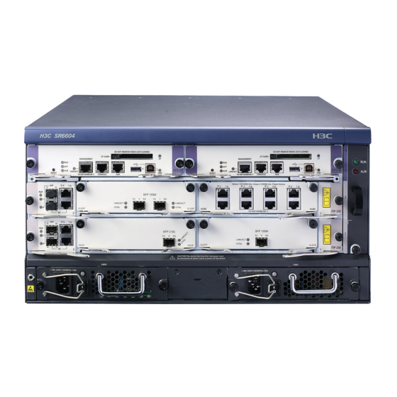
(4) Power supply slots NOTE: • The SR6604 router installed with RPE-X3, RPE-X5, or RPE-X5E MPUs has the same front view as installed with RPE-X1 MPUs. • Before installing an RPE-X1, RPE-X3, RPE-X5, or RPE-X5E MPU, install a compatible carrier in... - Page 8 Figure1-2 SR6604 front view (an RSE-X1 MPU installed) (1) MPU slot (slot 1) (2) MPU/service module/switching fabric module slot (slot 2) (3) Service module/switching fabric module slot (slot 3) (4) Power supply slots (5) Fan tray Figure1-3 SR6604 front view (an MCP-X1 installed)
-
Page 9: Sr6608
Figure1-4 SR6604 front view (an MCP-X2 installed) (1) MPU slot (slot 1) (2) MPU/service module/switching fabric module slot (slot 2) (3) Service module/switching fabric module slot (slot 3) (4) Power supply slots (5) Fan tray Figure1-5 SR6604 rear view (1) Rear cover handle... - Page 10 Figure1-6 SR6608 front view (an RPE-X1 MPU installed) (1) MPU slot (slot 0 and slot 1) (2) Service module/switching fabric module slots (slot 2 through slot 5) (3) Fan tray (4) Power supply slots NOTE: • The SR6608 router installed with RPE-X3, RPE-X5, or RPE-X5E MPUs has the same front view as installed with RPE-X1 MPUs.
- Page 11 Figure1-7 SR6608 front view (an RSE-X1 MPU installed) (1) MPU slot (slot 1) (2) MPU/service module/switching fabric module slot (slot 2) (3) Service module/switching fabric module slot (slot 3 through slot 5) (4) Power supply slots (5) Fan tray Figure1-8 SR6608 front view (an MCP-X1 installed) (1) MPU slot (slot 1) (2) MPU/Service module/switching fabric module slot (slot 2) (3) Service module/switching fabric module slots (slots 3 through 5)
- Page 12 Figure1-9 SR6608 front view (an MCP-X2 installed) (1) MPU slot (slot 1) (2) MPU/Service module/switching fabric module slot (slot 2) (3) Service module/switching fabric module slots (slots 3 through 5) (4) Power supply slots (5) Fan tray Figure1-10 SR6608-DS front view (1) MPU slots (slots 0 and 1) (2) Switching fabric module slot (slot 2) (3) Service module/switching fabric module slot (slot 3)
- Page 13 IMPORTANT: • An SFE-L2 switching fabric module is provided with the SR6608-DS router. As a best practice, install the module in slot 2. For the installation procedure, see H3C SR6604[6608] Routers Installation Guide. • To install an SFE-L2 switching fabric module in slot 3 on the SR6608-DS router, first install an SFU carrier in the slot.
-
Page 14: Dimensions And Weights
(3) Grounding terminal and sign (4) Air vents Dimensions and weights Chassis Table1-1 Dimensions and weights Specification Item SR6604 SR6608 Height (H) 220 mm (8.66 in) (5 RU) 308 mm (12.13 in) (7 RU) Width (W) 436 mm (17.17 in) 436 mm (17.17 in) -
Page 15: Power Supplies
Model Net weight Dimensions (H × W × D) RPE-X5E 0.95 kg (2.09 lb) 40 × 198.6 × 284.4 mm (1.57 × 7.82 × 11.20 in) RT-BKEB 44.1 × 376.6 × 414.8 mm (1.74 × 14.83 × 16.33 in) RT-BKEC 44.1 ×... -
Page 16: Power Consumption
Model Net weight Dimensions (H × W × D) PSR1200-D 2.25 kg (4.96 lb) 41 × 140 × 340 mm (1.61 × 5.51 × 13.39 in) Power consumption Cards Table1-4 Card power consumption Model Min. power consumption Max. power consumption RPE-X1 12.60 W 16.40 W... -
Page 17: Fan Trays
Fan trays Table1-5 Fan tray power consumption Model Power consumption SR6604 fan tray 28.30 W to 35.20 W SR6608 fan tray 28.90 W to 36.11 W 1-11... - Page 18 Contents 2 Removable components ·········································································· 2-1 MPUs ······························································································································································ 2-1 RPE-X1 ··················································································································································· 2-1 RPE-X3 ··················································································································································· 2-2 RPE-X5 ··················································································································································· 2-3 RPE-X5E ················································································································································· 2-4 RSE-X1 ··················································································································································· 2-5 MCP-X1/MCP-X2 ···································································································································· 2-6 Components ············································································································································ 2-7 Switching fabric modules ······························································································································ 2-11 SFE-L1 ·················································································································································· 2-11 SFE-L2 ·················································································································································· 2-12 Flexible interface platform modules ··············································································································...
-
Page 19: Removable Components
The RPE-X1, RPE-X3, RPE-X5, RPE-X5E, RSE-X1, MCP-X1, and MCP-X2 MPUs are available for the router. You can select them as needed. If you order an RPE-X1, RPE-X3, RPE-X5, or RPE-X5E MPU, you must also order a compatible carrier. For the MPU carrier installation procedure, see H3C SR6604[6608] Routers Installation Guide. RPE-X1... -
Page 20: Rpe-X3
Item Specification 9600 bps (default) to 115200 bps Management Ethernet port 1 (10Base-T/100Base-TX/1000Base-T) • 256 MB by default for the built-in CF card • CF card 256 MB, 512 MB, or 1 GB for an optional external CF card (CF cards less than 256 MB are not supported) 2 (USB 0: Type A connector, operating in the host mode;... -
Page 21: Rpe-X5
Item Specification USB console port Management Ethernet port 1 (10Base-T/100Base-TX/1000Base-T) USB port Host mode, type A connector Reset button Hot swapping Supported NOTE: • SDRAM stores running configuration and buffers data during data forwarding. • Non-volatile random access memory (NVRAM) stores system exception logs. RPE-X5 CAUTION: If you connect a large-sized USB drive directly to the RPE-X5 MPU, the right ejector lever of the... -
Page 22: Rpe-X5E
The Ethernet fiber ports SFP+0 and SFP+1 on the RPE-X5E MPU are only used for virtual machine services and do not support Layer 2 or Layer 3 forwarding. For information about how to use these two fiber ports, see H3C SR6600 Router Series VM Deployment Guide. Figure2-4 RPE-X5E MPU... -
Page 23: Rse-X1
NOTE: SDRAM stores running configuration and buffers data during data forwarding. RSE-X1 Figure2-5 RSE-X1 MPU (1) Reset button (RESET) (2) CF card button (3) CF card (4) CF card LED (5) Host-mode USB port 0 (0) (6) Device-mode USB port 1 (1) (8) LINK/ACT LED for the Ethernet management (7) USB 1 LED port... -
Page 24: Mcp-X1/Mcp-X2
MCP-X1/MCP-X2 Figure2-6 MCP-X1 (1) Combo interface 1 (2) Combo interface 3 (3) CF card slot (CF CARD) (4) CF card LED (CF) (5) Management Ethernet port (MANAGEMENT) (6) Console port (CONSOLE) (7) AUX port (AUX) (8) Reset button (RESET) (9) MCP-X1 status LED (10) USB port (11) Combo interface 2 (12) Combo interface 0... -
Page 25: Components
• 1 GB IMPORTANT: • Use CF cards provided by H3C only. The router might be incompatible with other CF cards. • CF cards less than 256 MB are not supported. Console port The router provides an RS232 asynchronous serial console port that can be connected to a computer for system debugging, configuration, maintenance, management, and host software loading. - Page 26 In the event that the console port fails, the AUX port can be connected to a terminal as a backup port of the console port. For more information about how to use the AUX port, see H3C SR6604[6608] Routers Installation Guide.
- Page 27 Management Ethernet port The management Ethernet port is a 10Base-T/100Base-TX/1000Base-T RJ-45 port. It allows you to upgrade software and manage the router through a network management server without using any service interfaces of the router. The management Ethernet port is used only for managing the router and it does not have service processing capabilities such as data forwarding.
- Page 28 Table2-12 Fiber Ethernet port specifications Item Specification Connector type Transceiver module type Interface standards 802.3, 802.3u, and 802.3ab Operating mode 1000 Mbps, full duplex 10 Gbps Ethernet port The MCP-X2 provides two 10 Gbps Ethernet ports. 10 Gbps SFP+ ports do not support 1000 Mbps transceiver modules.
-
Page 29: Switching Fabric Modules
Power button WARNING! The device might still have power after you press the power button. Do not reboot the RPE-X5E MPU or remove power cords from the RPE-X5E MPU until the power button/LED goes off. CAUTION: • Forced power-off might cause data loss in virtual machines. Please use it with caution. •... -
Page 30: Sfe-L2
Flexible interface platform modules IMPORTANT: Use transceiver modules for the flexible interface platform modules (FIPs) provided by H3C only. The router might be incompatible with transceiver modules from other vendors. The system generates an alarm when a transceiver module from another vendor is installed. - Page 31 H3C SR6600/SR6600-X Routers Interface Command Reference(V7). A FIP is a processing engine and you can install different interface modules in a FIP to support different network services as needed. This section describes the FIP modules available for the H3C SR6604 and SR6608 routers.
- Page 32 FIP: Table2-17 References for FIP operations Operation Reference Install and remove the FIP Install and remove interface modules H3C SR6604[6608] Routers Installation Guide Connect network cables Connect optical fibers Technical specifications Item Specification 2 HIMs supported 2 MIMs supported...
- Page 33 The OPEN BOOK mark indicates that the operator must read the following document before working with the FIP: Table2-18 References for FIP operations Operation Reference Install and remove the FIP Install and remove MIMs H3C SR6604[6608] Routers Installation Guide Connect network cables Connect optical fibers Technical specifications Item Specification Flash 4 MB •...
- Page 34 The OPEN BOOK mark indicates that the operator must read the following document before working with the FIP: Table2-21 References for FIP operations Operation Reference Install and remove the FIP H3C SR6604[6608] Routers Installation Guide Install and remove MIMs 2-16...
- Page 35 Operation Reference Connect network cables Connect optical fibers Technical specifications Item Specification Flash 4 MB • Default—Two 1-GB DDR2 SDRAMs Memory type and size • Maximum—Two 2-GB DDR2 SDRAMs NVRAM 128 KB 10 Mbps, half/full-duplex 2 copper ports (automatic Combo interfaces 100 Mbps, half/full-duplex MDI/MDIX) 1000 Mbps, full-duplex...
- Page 36 Technical specifications Item Specification Flash 8 MB • Default—One 2-GB DDR3 SDRAM Memory type and size • Maximum—Two 2-GB DDR3 SDRAMs NVRAM 128 KB 10 Mbps, half/full-duplex 2 copper ports (MDI/MDIX Combo interface 100 Mbps, half/full-duplex autosensing) 1000 Mbps, full-duplex 2 fiber ports 1000 Mbps, full-duplex 4 supported...
-
Page 37: Fip-300
(1) Captive screw (2) Slot 4 (3) Slot 3 (4) Ejector lever (5) Slot 1 (6) Slot 2 Technical specifications Item Specification Memory type and size 4GB DDR4 (Optional) 512 GB mSATA SSD NOTE: Drive The mSATA hard disk with SSC enabled is not supported on the FIP-260. Not supported Not supported Not supported... - Page 38 Item Specification 10 Mbps, half/full-duplex Copper ports (MDI/MDIX Combo interface 100 Mbps, half/full-duplex autosensing) 1000 Mbps, full-duplex Fiber ports 1000 Mbps, full-duplex Not supported Hardware encryption Supported Hot swapping Supported Combo interface specifications Specifications of combo interfaces on the FIP-300 and the FIP-110 are the same. For more information, see Table2-19 and Table2-20.
- Page 39 Item Specification NVRAM 128 KB 10 Mbps, half/full-duplex 2 copper ports (automatic Combo interfaces 100 Mbps, half/full-duplex MDI/MDIX) 1000 Mbps, full-duplex 2 fiber ports 1000 Mbps, full-duplex 10G Ethernet port Not supported Hardware encryption Supported Hot-swapping Supported Combo interface specifications Specifications of combo interfaces on the FIP-310 and the FIP-110 are the same.
-
Page 40: Fip-380
Front panel Figure2-18 FIP-380 front panel (1) Captive screw (2) Slot 2 (3) 10GBASE-R-SFP+ ports SFP+22 and SFP+23 (4) 1000BASE-X-SFP ports SFP0 to SFP13 (5) 100/1000 BASE-T Ethernet copper ports GE14 to GE21 (6) Ejector lever (7) Slot 1 Technical specifications Item Specification Memory type and size... - Page 41 1000BASE-X-SFP port specifications Table2-24 FIP-380 1000BASE-X-SFP port specifications Item Specification Connector Transceiver module type Interface standards 802.3, 802.3u, and 802.3ab Duplex mode 1000 Mbps, full duplex 100/1000BASE-T Ethernet copper port specifications Table2-25 FIP-380 100/1000BASE-T Ethernet copper port specifications Item Specification Connector RJ-45 Interface type...
-
Page 42: Fip-660
A FIP-660 provides four MIC-X interface module slots. When installing a FIP-660, if a service module slot adjacent to the FIP-660 is empty, install an air deflector over the slot. For information about installing an air deflector, see H3C SR6604[6608] Routers Installation Guide. Front panel... - Page 43 Air deflector Figure2-21 FIP-660 air deflector Technical specifications Item Specification Memory type and size 16GB DDR4 Drive Not supported Not supported Not supported Not supported MIC-X A maximum of 4 Hardware encryption Supported Hot swapping Supported FIP-680 The FIP-680 provides 4 SFP+ ports, 12 SFP ports, and 8 copper GE ports. It supports a maximum of two MICs.
- Page 44 Item Specification The SDRAMs must be used in pairs and must be the same size. NVRAM 128 KB 10GE fiber ports (SFP+) GE fiber ports (SFP) Copper Ethernet ports 10/100/1000M autosensing Not supported Not supported Hardware encryption Supported Hot-swapping Supported 10GE SFP+ port specifications Table2-26 FIP-680 10GE SFP+ port specifications Item...
-
Page 45: Service Aggregation Platform Modules
H3C SR6600/SR6600-X Routers Interface Command Reference(V7). A SAP module provides network ports for receiving packets from the network and sending packets to the network. This section describes the SAPs available for the H3C SR6604 and SR6608 routers. SAP-48GBE The SAP-48GBE has 48 high-performance RJ-45 ports that can be both routed and switched. -
Page 46: Sap-24Gbp
Item Specification Max power consumption 200 W Connector type RJ-45 Number of interfaces Interface standards 802.3, 802.3u, and 802.3ab Interface type Automatic MDI/MDIX Cable type Straight-through/crossover Ethernet cable Transmission distance 100 m (328.08 ft) Ethernet_II Supported frame format Ethernet_SNAP 10 Mbps Full/half duplex, auto-negotiation Interface speed and 100 Mbps... -
Page 47: Sap-48Gbp
Item Specification Interface standards 802.3, 802.3u, and 802.3ab Ethernet_II Supported frame format Ethernet_SNAP 1000 Mbps (recommended) Interface speed Full duplex Fixed Ethernet port specifications Specifications of the SAP-24GBP fixed Ethernet ports and the FIP-110 fiber combo ports are the same. For more information, see Table2-20. SAP-48GBP The SAP-48GBP has 48 high-performance fiber SFP ports that can be both routed and switched. -
Page 48: Sap-20Ge2Xp
Fixed Ethernet port specifications Specifications of the SAP-48GBP fixed Ethernet ports and the FIP-110 fiber combo ports are the same. For more information, see Table2-20. SAP-20GE2XP Front panel Figure2-26 SAP-20GE2XP front panel (1) SFP ports (GE0 to GE15) (2) Combo interfaces (GE16 to GE19) (3) SFP+ port 0 (4) SFP+ port 1 (5) Operating status LED (RUN) -
Page 49: Sap-28Ge
Table2-30 Copper combo port specifications Item Specification Connector type RJ-45 Interface type Auto MDI/MDI-X • Ethernet_II Frame format supported • Ethernet_SNAP 10 Mbps auto-sensing Half/full duplex, auto-negotiation Interface speed and duplex 100 Mbps auto-sensing Half/full duplex, auto-negotiation mode 1000 Mbps auto-sensing Full duplex, auto-negotiation For the fiber combo port specifications, see Table2-29. -
Page 50: Sap-Xp4Ge32
Item Specification • Copper port—Straight-through/crossover autosensing: 10/100 Mbps, half/full-duplex. 1000 Mbps, full-duplex. • Fiber port—1000 Mbps, full-duplex. Hot swapping Supported. Fixed Ethernet port specifications Table2-32 SFP port specifications Item Specification Connector type Transceiver module type Network synchronization Supported 1588v2.2 protocol Supported Interface standards... - Page 51 (1) Captive screw (2) 10/100/1000Base-T Ethernet copper ports GE0 to GE11 (3) Combo interfaces GE12 to GE23 (4) 1000BASE-X-SFP ports SFP24 to SFP31 (5) 10GBASE-R-SFP+ ports SFP+32 to SFP+35 (6) Operating status LED (RUN) (7) Ejector lever Technical specifications Item Specification Memory type and size 8GB DDR4...
-
Page 52: Hardware Compatibility Matrixes
For the copper combo port specifications, see Table2-34. For the fiber combo port specifications, see Table2-35. Hardware compatibility matrixes In the compatibility matrixes, "√" means "Supported" and "×" means "Not supported." MPU and Comware compatibility matrix Table2-37 MPU and Comware compatibility matrix Comware 5 Comware 7 √... -
Page 53: Interface Module And Comware Compatibility Matrix
Service RPE-X1 RPE-X3 RPE-X5 RPE-X5E RSE-X1 MCP-X1 MCP-X2 module √ SAP-48GBP × × × × × × √ SAP-20GE2XP × × × × × × √ SAP-28GE × × × × × × √ √ √ SAP-XP4GE32 × × × ×... -
Page 54: Ac Power Supplies
AC power supplies PSR650-A Figure2-29 PSR650-A view (1) AC-input power receptacle (2) Power switch (3) Handle (4) Status LED Table2-40 PSR650-A specifications Item Specification Rated input voltage 100 VAC to 240 VAC @ 50 or 60 Hz Maximum input current 10 A Maximum power 650 W... -
Page 55: Dc Power Supplies
Item Specification Maximum power 1213 W DC power supplies PSR650-D Figure2-31 PSR650-D view (1) DC-input terminal block (2) Power switch (3) Handle (4) Status LED Table2-42 PSR650-D specifications Item Specification Rated input voltage –48 VDC to –60 VDC Maximum input current 25 A Maximum power 650 W... -
Page 56: Fan Trays
Maximum input current 42 A Maximum power 1213 W Fan trays The fan tray structures of the SR6604 and SR6608 are similar. Figure2-33 SR6604 fan tray Figure2-34 SR6608 fan tray (1) Fan tray status LED (RUN) (2) Alarm LED (ALM) -
Page 57: Transceiver Modules
The specifications for the power strip with lightning protection that can be installed on the router are as follows: Maximum discharge current: 6500 A, protection voltage: 500 VAC to 220 VAC. For information about how to install a power strip with lightning protection, see H3C SR6604[6608] Routers Installation Guide. Surge lightning protector Generally, you need to connect a surge protector before connecting a signal cable to the router. - Page 58 • Surge protector—Maximum discharge current 2.5KA/protection voltage 25V-BNC-75K/ BNC-75K-10Mbps • Surge protector (U port)—Maximum discharge current 3KA/common-mode 400V/differential mode 170V-RJ11 For information about how to install a surge lightning protector, see H3C SR6604[6608] Routers Installation Guide. 2-40...
- Page 59 Contents 3 LEDs ········································································································ 3-1 MPU LEDs ······················································································································································ 3-3 Switching fabric module LEDs ······················································································································ 3-12 FIP LEDs ······················································································································································· 3-12 SAP LEDs ····················································································································································· 3-19 HIM/MIM/MIC/MIC-X LEDs ··························································································································· 3-23 Power module LEDs ····································································································································· 3-24 Fan tray LEDs ··············································································································································· 3-25...
-
Page 60: Leds
LEDs The MPUs, switching fabric modules, FIPs, SAPs, HIM/MIM/MICs, power modules, and fan trays available for the router provide various LEDs to indicate the operating status. Table3-1 H3C SR6604 and SR6608 routers LEDs Remarks Run LED (RUN) Active LED (ACT) - Page 61 1000 Mbps fiber Ethernet port LED (SFP0 and SFP1) Run LED (RUN) Table3-18 SAP LEDs Table3-19. 10/100/1000 Mbps Ethernet port LED HIM/MIM/MIC/ See H3C SR6600/SR6600-X Routers Interface Module Guide. MIC-X LEDs Power module LEDs Power LED See Table3-24. Run LED (RUN) Fan tray LEDs See Table3-25.
-
Page 62: Mpu Leds
MPU LEDs CAUTION: To avoid damaging the file system on the CF card, do not remove the CF card when the CF LED is flashing. Figure3-1 LEDs on the RPE-X1 Table3-2 RPE-X1 LED description Status Description No power input is available, or the RPE-X1 has failed. Slow flashing (1 The RPE-X1 is operating correctly. - Page 63 Status Description (green) A host is connected to the device-mode USB port. The Steady on USB cable can be unplugged in this state. Data is being transmitted or received through the Flashing device-mode USB port. In this state, do not unplug the USB cable.
- Page 64 Figure3-3 LEDs on the RPE-X5 Table3-4 RPE-X5 LED description Status Description Fast flashing The BIOS is operating correctly. green Slow flashing No or insufficient memory or initialization yellow failure. BIOS stage Fast flashing The extended segment does not exist. yellow Hardware failure or no power input.
- Page 65 Status Description (yellow/green) Flashing green Data is being received or transmitted at 1000 Mbps. Steady yellow A 100 Mbps link is present. Flashing yellow Data is being received or transmitted at 100 Mbps. No link is present or the port is faulty. Fast flashing (10 USB-based automatic configuration has failed.
- Page 66 Status Description Slow flashing The system is operating correctly. green Comware Fast flashing stage USB-based automatic configuration green (5 has succeeded. seconds) Steady on The system power is insufficient. PALM The power system is operating correctly. (red) Slow flashing The device is in IRF mode and the MPU is the global green active MPU.
- Page 67 Status Description Steady red The shutdown of the Comware system is in progress. The Comware system has shut down. Figure3-5 RSE-X1 LEDs Table3-6 RSE-X1 LED description Status Description No CF card is present or the CF card is not recognizable. Steady on A CF card is in position and has been detected.
- Page 68 The system is accessing the CF card. In this Flashing green (yellow/green) state, do not remove the CF card. Steady yellow A CF card not provided by H3C. No power input is available, or the MCP-X1 has failed. Slow flashing (1 The MCP-X1 is operating correctly.
- Page 69 Steady green A CF card is in position and has been detected. The system is accessing the CF card. In this state, Flashing green (yellow/green) do not remove the CF card. Steady yellow A CF card not provided by H3C. 3-10...
- Page 70 Status Description No power input is available, or the MCP-X1 has failed. Slow flashing The MCP-X1 is operating correctly. (1 Hz) (green) The application software is being loaded (in this Fast flashing case, never power off the device or hot-swap the (8 Hz) MCP-X1;...
-
Page 71: Switching Fabric Module Leds
Switching fabric module LEDs Figure3-8 SFE-L1 status LED Figure3-9 SFE-L2 status LED Table3-9 SFE-L1 LED description Status Description No link is present or the module is faulty. Slow flashing (1 The module is operating correctly. Application software is being loaded. (green) Fast flashing (8 To avoid damage to the module, do not power off... - Page 72 Figure3-11 FIP-20 status LED Table3-10 FIP-10/20 LED description Status Description No link is present or the FIP is faulty. Slow flashing (1 The FIP is operating correctly. System software is being loaded. To avoid damage (green) Fast flashing (8 to the FIP, never power off the device or hot-swap the FIP while the system software is being loaded.
- Page 73 Figure3-14 FIP-240 LEDs Figure3-15 FIP-600 LEDs Table3-11 FIP-110/210/240/600 LED description Status Description No link is present. Steady green A 1000 Mbps link is present. 10/100/1000 Mbps copper Flashing green Data is being received or transmitted at 1000 Mbps. Ethernet port Steady yellow A 10/100 Mbps link is present.
- Page 74 Figure3-16 FIP-260 LEDs Table3-12 FIP-260 LED description Status Description No power input is available or the FIP-260 has failed. Fast flashing (8 System software is being loaded. Steady green The FIP software system is starting up. (green) Slow flashing (1 The FIP is operating correctly.
- Page 75 Figure3-18 FIP-310 LEDs Table3-14 FIP-310 LED description Status Description No link is present. Steady green A 1000 Mbps link is present. GE0 through Flashing green Data is being received or transmitted at 1000 Mbps. Steady yellow A 10/100 Mbps link is present. (yellow/green) Flashing yellow Data is being received or transmitted at 10/100 Mbps.
- Page 76 Status Description No link is present or the port has failed. Steady yellow A 1000 Mbps link is present. Flashing yellow SFP+22 and Data is being received or transmitted at 1000 Mbps. (8 Hz) SFP+23 Steady green A 10 Gbps link is present. (yellow/green) Flashing green Data is being received or transmitted at 10 Gbps.
- Page 77 Status Description Slow flashing (1 The FIP is operating correctly. Figure3-21 FIP-680 LEDs Table3-17 FIP-680 LED description Status Description No link is present. SFP1 through Steady green A 1000 Mbps link is present. SFP12 (green) Flashing green Data is being received or transmitted at 1000 Mbps. No link is present.
-
Page 78: Sap Leds
SAP LEDs Figure3-22 SAP LEDs(SAP-48GBE) Table3-18 SAP-48GBE LED description Item Status Description No link is present. Steady green A 1000 Mbps link is present. Status LEDs of Flashing green Data is being received or transmitted at 1000 Mbps. GE 0 through Steady yellow A 10/100 Mbps link is present. - Page 79 Status Description No link is present. Steady green A 1000 Mbps link is present. Status LEDs of SFP 0 to Flashing green Data is being received or transmitted at 1000 Mbps. SFP 23 (yellow/green) Steady yellow A 100 Mbps link is present. Flashing yellow Data is being received or transmitted at 100 Mbps.
- Page 80 Status Description System software is being loaded or the SAP-20GE2XP is not operating. CAUTION: Fast flashing (8 To avoid hardware damage, do not power off the router, or insert or remove the SAP-20GE2XP when system software is being loaded. No link is present. Steady green A 10 Gbps link is present.
- Page 81 Table3-22 SAP-28GE LED description Status Description No power input is available or the SAP-28GE has failed. Slow flashing (1 Hz) The SAP-28GE is operating correctly. System software is being loaded or the SAP-28GE is not operating. (green) CAUTION: Fast flashing (8 Hz) To avoid hardware damage, do not power off the router, or insert or remove the SAP-28GE when system software is being loaded.
-
Page 82: Him/Mim/Mic/Mic-X Leds
Fast flashing (8 Hz) To avoid hardware damage, do not power off the router, or insert or remove the SAP-28GE when system software is being loaded. HIM/MIM/MIC/MIC-X LEDs For HIM/MIM/MIC/MIC-X LED description, see H3C SR6600/SR6600-X Routers Interface Module Guide. 3-23... -
Page 83: Power Module Leds
Power module LEDs Figure3-28 PSR650-A AC power module LED Figure3-29 PSR1200-A AC power module LED Figure3-30 PSR650-D DC power module LED Figure3-31 PSR1200-D DC power module LED Table3-24 AC/DC power LED description Status Description Steady green The power module is operating correctly. Power LED Steady red The power module is faulty. -
Page 84: Fan Tray Leds
Fan tray LEDs Figure3-32 Fan tray for the SR6604 Figure3-33 Fan tray for the SR6608 Table3-25 Fan tray LED description Status Description The system is powered off or the fan tray is faulty. Steady on The fan tray is operating correctly. - Page 85 Contents 4 Slot arrangment and interface numbering ················································ 4-1 Slot arrangement············································································································································· 4-1 Slot arrangement for MPUs, switching fabric modules, and service modules ················································ 4-3 Numbering interfaces ······································································································································ 4-3 Examples ························································································································································ 4-4 Example 1 ··············································································································································· 4-4 Example 2 ··············································································································································· 4-4...
-
Page 86: Slot Arrangment And Interface Numbering
The router provides multiple types of ports, including console port, AUX port, GigabitEthernet port, serial (synchronous) port, POS port, and E1 port. Figure4-1 Slot arrangement on the SR6604 configured with an RPE-X1/RPE-X3/RPE-X5/RPE-X5E MPU Figure4-2 Slot arrangement on the SR6604 configured with an RSE-X1 or MCP-X1/X2 MPU... - Page 87 Figure4-3 Slot arrangement on the SR6608 configured with an RPE-X1/RPE-X3/RPE-X5/RPE-X5E MPU Figure4-4 Slot arrangement on the SR6608 configured with an RSE-X1 or MCP-X1/X2 MPU NOTE: • The numbers in Figure4-1 through Figure4-4 represent corresponding slot numbers. • On a router configured with an RSE-X1 or MCP-X1/X2 MPU, the slots are numbered from 1 instead 0.
-
Page 88: Slot Arrangement For Mpus, Switching Fabric Modules, And Service Modules
Table4-1 Slot arrangement for MPUs, switching fabric modules, and service modules MPUs, switching fabric Slot arrangement on the Slot arrangement on the modules, and service SR6604 SR6608 modules MPUs RPE-X1/RPE-X3/RPE-X5/ Slot 0 and slot 1 RPE-X5E (supporting 1+1 An SR6608-DS router does not support the RPE-X1 MPU. -
Page 89: Examples
• interface-type—Type of the interface such as GE port and serial port. • X—Number of the slot where the FIP/SAP resides, in the range of 2 to 3 on the SR6604 and 2 to 5 on the SR6608. • Y—Number of the slot where the HIM/MIM/MIC/MIC-X resides on the FIP. For a SAP, the subslot number is 0.
Need help?
Do you have a question about the SR6604 and is the answer not in the manual?
Questions and answers