H3C SR6604 Installation Manual
Hide thumbs
Also See for SR6604:
- Installation manual (150 pages) ,
- Manual (89 pages) ,
- Configuration manual (23 pages)

Related Manuals for H3C SR6604


Summary of Contents for H3C SR6604
- Page 1 H3C SR6604 & SR6608 Routers Installation Guide New H3C Technologies Co., Ltd. http://www.h3c.com Document version: 6W127-20190315...
- Page 2 The information in this document is subject to change without notice. All contents in this document, including statements, information, and recommendations, are believed to be accurate, but they are presented without warranty of any kind, express or implied. H3C shall not be liable for technical or editorial errors or omissions contained herein.
- Page 3 Preface The H3C SR6604 & SR6608 Routers Installation Guide includes eight chapters, which describe the hardware features of the H3C SR6604 & SR6608 Routers and provide examples to help you install the router. This preface includes the following topics about the documentation: •...
- Page 4 Symbols Convention Description An alert that calls attention to important information that if not understood or followed WARNING! can result in personal injury. An alert that calls attention to important information that if not understood or followed CAUTION: can result in data loss, data corruption, or damage to hardware or software. An alert that calls attention to essential information.
- Page 5 Documentation feedback You can e-mail your comments about product documentation to info@h3c.com. We appreciate your comments.
-
Page 6: Table Of Contents
Contents Preparing for installation ···································································· 1 Safety recommendations ············································································································· 1 Safety symbols ··················································································································· 1 General safety recommendations ··························································································· 1 Electricity safety ·················································································································· 1 Laser safety ······················································································································· 2 Router moving ···················································································································· 2 Examining the installation site ······································································································· 2 ... - Page 7 Connecting the AUX cable ·································································································· 36 Connecting an Ethernet cable ····································································································· 37 Overview ························································································································· 37 Making an Ethernet cable ···································································································· 39 Connecting an Ethernet cable ······························································································ 39 Connecting a fiber cable ············································································································ 39 Transceiver module overview ······························································································· 39 ...
- Page 8 System software image file missing errors ····················································································· 90 Appendix A Chassis views and technical specifications ·························· 91 Chassis views ························································································································· 91 SR6604 ··························································································································· 91 SR6608 ··························································································································· 93 Dimensions and weights ············································································································ 98 Power consumption ·················································································································· 99 ...
- Page 9 SFE-L2 ························································································································· 115 Flexible interface platform modules ···························································································· 116 FIP-10 ··························································································································· 116 FIP-20 ··························································································································· 117 FIP-110 ························································································································· 118 FIP-210 ························································································································· 119 FIP-240 ························································································································· 121 FIP-260 ························································································································· 122 FIP-300 ························································································································· 122 FIP-310 ························································································································· 123 ...
-
Page 10: Preparing For Installation
Preparing for installation Table 1 shows the model and product code matrix for the H3C SR6604 and SR6608 routers. Table 1 Router model and product code matrix Model (on the front panel) Product code H3C SR6604 RT-SR6604-Chassis-H3 RT-SR6608-Chassis-H3 H3C SR6608... -
Page 11: Laser Safety
Laser safety WARNING! • The router is a Class 1 laser device. • Disconnected optical fibers or transceiver modules might emit invisible laser light. Do not stare into beams or view directly with optical instruments when the router is operating. Router moving CAUTION: Do not hold the handle of the fan tray or power module, the handle on the rear cover of the chassis,... -
Page 12: Altitude
Table 3 Humidity requirements Item Humidity Operating humidity (noncondensing) 10% RH to 95% RH Storage humidity (noncondensing) 5% RH to 95% RH Altitude Table 4 Altitude requirements Item Altitude Operating altitude –60 m to +4000 m (–196.85 to +13123.36 ft) Storage altitude –60 m to +4500 m (–196.85 to +14763.78 ft) Cleanliness... -
Page 13: Esd Prevention
Figure 1 Airflow ESD prevention CAUTION: Make sure the resistance reading between human body and the ground is in the range of 1 to 10 megohms (Mohms). To prevent electrostatic discharge (ESD), note the following guidelines: • Make sure the router and the floor are reliably grounded. •... -
Page 14: Emi
Figure 2 Attaching an ESD wrist strap (1) ESD wrist strap (2) Lock (3) Alligator clip All electromagnetic interference (EMI) sources, from outside or inside of the router and application system, adversely affect the router in the following ways: • A conduction pattern of capacitance coupling. -
Page 15: Space
• A minimum of 95 mm (3.74 in) 480 mm (18.90 in) for the chassis between the front rack posts and SR6604 AC 95 mm (3.74 in) for the cable the front door SR6604 DC management brackets at the chassis •... -
Page 16: Power Supply
Power supply • Make sure the power supply system at the installation site is stable and meets the requirements of the power modules, including the rated input voltage. • Select power modules based on the power consumption of the cards and fan trays. For more information about system power consumption and technical specifications of power modules, "Power consumption"... - Page 17 Item Requirements Result • The equipment and floor are reliably grounded. • The equipment room is dust-proof. • The humidity and temperature are in the acceptable range. • Wear an ESD wrist strap and uniform when touching a circuit board. ESD prevention •...
-
Page 18: Installing The Router
Installing the router IMPORTANT: Keep the packages of your router and its accessories safely for future use. Figure 3 Router installation flow Start Install the router in a 19-inch rack Connect the grounding cable Install MPUs Install optional Install FIP modules components? Install SAPs/OAPs Install interface modules... -
Page 19: Installing The Router In A 19-Inch Rack
• The SR6608 router is heavy. For rack stability, install it at a lowest possible position. Installing the router in a 19-inch rack This section uses an SR6604 as an example. Attaching cage nuts to the rack Determine where to install the router in the rack, and then install a rack shelf on the rack. -
Page 20: Installing The Cable Management Brackets
Figure 5 Installing cage nuts Installing the cable management brackets As shown in Figure 6, attach the cable management bracket to the left mounting bracket with screws before attaching it to the router. The SR6608-DS router is shipped with the cable management bracket attached to the left mounting bracket. -
Page 21: Attaching The Mounting Brackets To The Router
Attaching the mounting brackets to the router Before installing the router in a rack, attach the front mounting brackets to the two sides of the router. To attach the front mounting brackets to the router, align the screw holes on the mounting brackets with the screw holes on the router chassis, and then fasten the screws. -
Page 22: Grounding The Router
Figure 8 Attaching the router to the rack Grounding the router WARNING! Correctly connecting the router grounding cable is crucial to lightning protection and EMI protection. To connect the grounding cable: Remove the grounding screws from the grounding terminal on the rear panel of the router chassis. -
Page 23: Installing An Mpu
Figure 9 Connecting the grounding cable to the grounding hole of router NOTE: • Make sure the resistance reading between router chassis and the ground is smaller than 5 ohms. • To guarantee the grounding effect, use the grounding cable provided with the router to connect to the grounding strip in the equipment room as long as possible. -
Page 24: Installing An Rpe-X1/Rpe-X3/Rpe-X5/Rpe-X5E Mpu
Installing an RPE-X1/RPE-X3/RPE-X5/RPE-X5E MPU Before installing an RPE-X1, RPE-X3, RPE-X5, or RPE-X5E MPU, install a compatible carrier in the MPU slot. The RPE-X1 MPU supports the BKEB carrier, the RPE-X3 MPU supports the BKEC carrier, and the RPE-X5/RPE-X5E MPU supports the BKED carrier. For the carrier model, see the barcode on the carrier. -
Page 25: Installing An Rse-X1 Mpu
Figure 12 Inserting the RPE-X1 into the slot Fasten the captive screws on the RPE-X1. Observe the RUN LED on the RPE-X1 to verify that the RPE-X1 is installed correctly. After the router is powered on, the RUN LED on the RPE-X1 flashes green at 8 Hz until the application software is loaded. -
Page 26: Installing An Mcp Mpu
Figure 13 Inserting the RSE-X1 into the slot Fasten the captive screws on the RSE-X1. Observe the RUN LED on the RSE-X1 to verify that the RSE-X1 is installed correctly. After the router is powered on, the RUN LED on the RSE-X1 flashes green at 8 Hz until the application software is loaded. -
Page 27: Installing An Ssd Drive
FIP-380, and SAP-XP4GE32 modules do not support SSD drives with SSC enabled. No SSD drive or screws are provided with the router. As a best practice, purchase an SSD drive and screws from H3C as needed. To install an SSD drive:... - Page 28 Figure 15 FIP-260 (1) Front panel (2) SSD drive slot Align the golden plating on the SSD drive with the mSATA connector in the slot. Slightly press the SSD drive until it is level with the surface of the connector. Use a Phillips screwdriver to screw the SSD drive into place.
-
Page 29: Installing A Fip Module And An Air Deflector
Installing a FIP module and an air deflector Installing a FIP module IMPORTANT: FIP-10 and FIP-20 can operate correctly only on a router installed with an MCP. The router supports hot swapping of FIP modules. The installation procedure is similar for FIPs. The following procedure installs a FIP-210. To install a FIP module: Locate the slot to install the FIP module. -
Page 30: (Optional) Installing An Air Deflector
(Optional) Installing an air deflector For a FIP-660, if a service module slot adjacent to the FIP-660 is empty, install an air deflector over the slot. To install an air deflector: Locate the service module slot to install the air deflector. Loosen the captive screws on the filler panel, and then remove the filler panel. -
Page 31: Installing A Him/Mim/Mic/Mic-X Interface Module
Figure 19 Inserting a SAP module Fasten the captive screws on the SAP module. Observe the RUN LED on the SAP to verify that the SAP module is installed correctly. After the router is powered on, the RUN LED on the SAP flashes green once and then fast flashes (at 8 Hz) until the application software is loaded. - Page 32 MIC-X adapter module components Figure 20 Screw Figure 21 Carrier Figure 22 Front panel Assembling a MIC-X adapter module and MIC interface module into a MIC-X interface module Use a screwdriver to remove the four screws from the MIC interface module circuit board so that the front panel and the gasket are disengaged from the circuit board.
-
Page 33: Installing An Interface Module
Figure 23 Assembling a MIC-X adapter module and a MIC interface module into a MIC-X interface module Gently push the MIC interface module circuit board into the MIC-X adapter module Installing an interface module The installation procedure is the same for HIM, MIM, MIC, and MIC-X interface modules. To install a HIM/MIM/MIC/MIC-X interface module: Locate the slot to install the target module on the FIP module. -
Page 34: Installing A Fan Tray
Figure 24 Pushing the module into the slot Fasten the captive screws on the module. Observe the LED for the slot on the router front panel to verify that the module is installed correctly. If the LED is on after the module initialization completes, the module has been installed correctly and is operating correctly. -
Page 35: Installing A Cf Card
Fasten the captive screws on the fan tray. Power on the router and check the status LED on the front panel. On means the fan tray is operating correctly. Off means the fan tray has failed the POST. For the LED description of the fan tray, see "Appendix C LEDs."... -
Page 36: Connecting A Power Cord
Connecting a power cord Connecting an AC power cord Make sure the power is OFF. Make sure the router is reliably grounded. Connect one end of the AC power cord to the AC receptacle on the router, and the other end to the AC power source. - Page 37 Connect the other end of the DC power cord to the DC power source. Install the protection cover of the DC power module. Figure 30 Connecting the DC power cord Connecting the power cord for the PSR1200-D Figure 31 DC power cord To connect the DC power cord: Loosen the captive screws on the power module to remove the power module connector.
- Page 38 Insert the power module connector in right direction into the power module, and fasten the captive screws. Figure 33 Installing the power module connector to the power module Connect the other ends of the power cords to the DC power source.
-
Page 39: Installing Frus
Installing FRUs Field replaceable units (FRUs) are not provided with the router. Purchase them as needed. Installing an air filter Position the upper slide rail horizontally near the top of the left side of the chassis, as shown Figure 34. Align the screw holes on the slide rail with those on the chassis. Fasten the fastening screws one by one. -
Page 40: Installing A Fiber Management Tray
Figure 36 Fastening the captive screws Installing a fiber management tray Preparations Confirm the following prerequisites: • The rack is fixed. • The router is installed. The installation involves the following materials: • Fiber management tray (FMT) • M5 × 10 self-tapping screws (two screws for one FMT) Installation procedure To install an FMT: Align the FMT and the installation holes on the rack post. -
Page 41: Installing A Lightning Protector For A Network Port
Installing a lightning protector for a network port Lightning protectors are applicable to only 10/100 Mbps copper Ethernet ports. Read the instructions for the lightning protector carefully before you install it. The router does not come with any lightning protectors. If part of the network cable of a copper Ethernet port must be routed outdoors, connect a lightning protector to the cable before you plug the cable into the port. -
Page 42: Connecting The Ac Power Supply To A Power Strip With Lightning Protection
• The installed port lighting protectors are not sufficient. If the router has more than one network port connected with other devices through cables outdoor, install a lightning protector for each network port. Connecting the AC power supply to a power strip with lightning protection CAUTION: Make sure the PE terminal of the power socket has been securely grounded. -
Page 43: Installing A Surge Protector (Optional)
Installing a surge protector (optional) CAUTION: Ground the surge protector as near as possible. The grounding resistance must be less than 4 ohms. The grounding resistance must be less than 1 ohm if there are special grounding requirements. Generally, you need to connect a surge protector before connecting a signal cable to the router. This can protect electronic devices against surge over-voltage resulting from lightning strokes and other interferences, and minimize impact on the router. - Page 44 Figure 40 Installing a surge protector Precautions The performance of the surge protector might be affected in the following cases: • The surge protector is installed in reverse direction. Connect the IN end to the outdoor network cable and the OUT end to the network port on the router. •...
-
Page 45: Connecting Interface Cables
Connecting interface cables Connecting the AUX cable Overview An AUX console cable is an 8-core shielded cable, with a crimped RJ-45 connector at one end for connecting to the AUX port of the router, and DB-25 and DB-9 male connectors at the other end for connecting to the serial port of the modem. -
Page 46: Connecting An Ethernet Cable
Figure 42 Connecting the AUX port to a modem Connecting an Ethernet cable Overview 10/100 Mbps Ethernet uses category-5 twisted pair cables, while 1000 Mbps Ethernet uses category-5 enhanced or category-6 twisted pair cables. Twisted pair cables include straight-through cables and crossover cables. Category-5 cables provide a transmission frequency of 100 MHz for voice and data transmission;... - Page 47 Figure 43 RJ-45 connector pinout PIN #8 PIN #1 EIA/TIA cabling specifications define two standards, 568A and 568B, for cable pinouts. • Standard 568A—Pin 1: white/green stripe, pin 2: green steady, pin 3: white/orange stripe, pin 4: blue steady, pin 5: white/blue stripe, pin 6: orange steady, pin 7: white/brown stripe, pin 8: brown steady.
-
Page 48: Making An Ethernet Cable
NOTE: To avoid affecting communication quality, strictly follow the pinouts in the above tables when identifying or making the two types of Ethernet cables. Making an Ethernet cable Cut the cable to a required length with the crimping pliers. Strip off an appropriate length of the cable sheath. The length is typically that of the RJ-45 connector. -
Page 49: Fiber Cable Overview
Figure 45 XFP transceiver module Figure 46 SFP+ transceiver module Fiber cable overview You can use an optical fiber to connect a fiber Ethernet port or 10 Gbps Ethernet port. In addition, an optical fiber connect these types interface modules: HIM-4GBP/HIM-8GBP, HIM-CL1P/HIM-CL2P, HIM-CLS1P/HIM-CLS2P,... -
Page 50: Connecting A Fiber Cable
Insert and remove a plug with care. Never exert a fierce force to the fiber or plug; otherwise the plug might be damaged or the fiber might be broken. Never pull, press or extrude the fiber fiercely. For the allowed maximum tensile load and crush load, see Table Table 11 Characteristics of single-mode and multi-mode optical fibers Item... - Page 51 Figure 48 Removing the dust plug Install the transceiver module. Figure 49 Installing the transceiver module...
-
Page 52: Connecting An E1/T1 Cable
Identify the Rx and Tx ports. Plug the LC connector at one end of one fiber cable into the Rx port of the router and the LC connector at the other end into the Tx port of the peer device. Plug the LC connector at one end of another fiber cable into the Tx port of the router and the LC connector at the other end to the Rx port of the peer device. -
Page 53: Connecting An E1/T1 Cable
Figure 51 8E1 splitter cable NOTE: The coaxial connector and 75-ohm E1 adapter cable are optional accessories, and must be purchased separately if needed. T1 cable You can use an 8T1 interface cable to connect to MIM-8T1/MIM-8T1-F modules. Figure 52 8T1 splitter cable Connecting an E1/T1 cable Connecting an E1 cable (D15/D68 <---->... - Page 54 b. The other end of the cable provides one pair or multiple pairs of 75-ohm BNC connectors. Connect the TX connectors and the RX connectors on this end to the RX connectors and the TX connectors on the remote device respectively. Figure 53 Connect an E1 75-ohm cable •...
-
Page 55: Connecting A Ce3/Ct3/T3 Cable
Connecting a T1 cable Connect the D68 connector of the 8-port T1 cable to the D68 interface on the interface module and fasten the bolts to fix the cable. The other end of the cable provides eight RJ-45 connectors. Connect them to the RJ-45 interface on the remote device as needed. -
Page 56: Connecting A Serial Port Cable
Figure 58 Connecting a CE3/CT3/T3 cable Connecting a serial port cable Overview You can use a serial port cable to connect to the MIM-2SAE/MIM-4SAE/MIM-8SAE module. Select a serial port cable according to the link type. Figure 59 V.24 DTE cable Figure 60 V.24 DCE cable... - Page 57 Figure 61 V.35 DTE cable Figure 62 V.35 DCE cable Pos.28 Pos.1 Figure 63 X.21 DTE cable Pos.1 Pos.1 Pos.15 Pos.28 Figure 64 X.21 DCE cable Figure 65 RS449 DTE cable...
-
Page 58: Connecting A Serial Port Cable
Figure 66 RS449 DCE cable Figure 67 RS530 DTE cable Figure 68 RS530 DCE cable Connecting a serial port cable Check port type of the peer device and choose the synchronous serial interface cable of correct type. Plug the D28 end of the synchronous serial interface cable into the D28 interface of the SAE interface module. -
Page 59: Accessing The Router
Accessing the router Login methods The following logins methods are available for you to log in to the router: • Logging in from the console port, which is the most common way to log in to a router and also the prerequisite for configuring other login methods. - Page 60 Click the following link, or copy it to the address bar on the browser to log in to download page of the USB console driver, and download the driver. http://www.h3c.com.hk/Technical_Support___Documents/Software_Download/Routers/USB_ Console/USB_Console/ Select a driver program according to the operating system you use: XR21V1410_XR21B1411_Windows_Ver1840_x86_Installer.EXE—Applicable to 32-bit...
- Page 61 Figure 70 Device driver installation wizard Click Continue Anyway if the following dialog box appears. Click Finish.
-
Page 62: Setting Terminal Parameters
Figure 71 Completing the device driver installation wizard Setting terminal parameters To configure and manage the router through the console port, you must run a terminal emulator program, TeraTermPro or PuTTY, on your configuration terminal. You can use the emulator program to connect a network device, a Telnet site, or an SSH site. -
Page 63: Checking After Power-On
Press Ctrl+D to access BASIC-BOOTWARE MENU Press Ctrl+T to start memory test Booting Normal Extend BootWare..**************************************************************************** H3C SR66 BootWare, Version 7.1.064 **************************************************************************** Copyright (c) 2004-2017 New H3C Technologies Co., Ltd. Compiled Date : Apr 6 2017 CPU Type : XLS408... -
Page 64: Logging In To The Router Through Telnet
Specify an IP address for the PC, make sure the PC and the interface are in the same network segment. For more information about how to log in to the router through Telnet, see H3C SR6600/SR6600-X Routers Fundamentals Configuration Guide. - Page 65 Step Command Remarks ip address ip-address Specify an IP address for By default, no IP address is { mask-length | mask } the interface. assigned to any interfaces. [ sub ] Return to system view. Available in any view. quit ip route-static dest-address { mask | mask-length }...
-
Page 66: Hardware Management And Maintenance
Hardware management and maintenance The output depends on your router model. For more information about the commands used in this chapter, see H3C SR6600/SR6600-X Routers Command References. Displaying hardware information of the router Displaying the software and hardware version information of... -
Page 67: Displaying Detailed Information About A Module
…Omitted… Displaying detailed information about a module Use the display device verbose command to display detailed information about modules in each slot. <Sysname>display device verbose System-mode(Current/After Reboot): Normal/Normal Slot No. Board type Status Primary SubSlots --------------------------------------------------------------------- RPE-X1 Normal Master Absent Absent Absent Absent... -
Page 68: Displaying The Cpu Usage Of A Module
MANUFACTURING_DATE:NONE VENDOR_NAME:H3C Slot 5: DEVICE_NAME:NONE DEVICE_SERIAL_NUMBER:NONE MAC_ADDRESS:NONE MANUFACTURING_DATE:NONE VENDOR_NAME:H3C Use the display device manuinfo slot slot-number command to display the electrical label information of the module in the specified slot. <Sysname> display device manuinfo slot 5 Slot 5: DEVICE_NAME:NONE DEVICE_SERIAL_NUMBER:NONE... -
Page 69: Displaying The Memory Usage Of A Module
Table 15 Output description Field Description CPU usage of the module in slot 0. If the module in the slot has multiple CPUs, Slot 0 CPU usage shows the Slot 0 CPU usage usage of the main CPU of the module in slot 0, and Slot 0 CPU 1 CPU usage shows the usage of the standby CPU of the module in slot 0. -
Page 70: Displaying The Operational Status Of The Fan
Field Description Operational status of the CF card: • Absent—No CF card is present in the slot. Status • Fault—The CF card fails. • Normal—The CF card is operating correctly. Size (M) Storage capacity of the CF card Displaying the operational status of the fan Use the display fan command to display the operational status of the fan. -
Page 71: Port Configuration And Management
To display the alarming thresholds of a module: Step Command Remarks Enter system view. system-view Optional Display the temperature display environment information of your router. Available in any view Port configuration and management Configuring a combo interface Combo interface overview A combo interface is a logical interface comprising an SFP port of a transceiver module and an RJ-45 Ethernet port. -
Page 72: Displaying Transceiver Module Information And Alarming Information
The system outputs alarm information for you to locate and troubleshoot faults of transceiver modules. For the H3C-customized transceiver modules, the system can also monitor the key parameters, such as temperature, voltage, laser bias current, TX power, and RX power. When these parameters are abnormal, you can take corresponding measures to prevent transceiver module faults. -
Page 73: Saving The Current Configuration Of The Router
[ interface-type module in a specified interface interface-number ] For more information about the transceiver module displaying commands, see H3C SR6600/SR6600-X Routers Fundamentals Command Reference. Saving the current configuration of the router You can save the current configuration of the router in one of the following methods: •... - Page 74 If you are performing file operations when the router is to be rebooted, the system does not execute the reboot command for security. To reboot the router immediately: Task Command Remarks Required. Available in user view. If you execute the command without specifying the slot Reboot the router or keyword, the command reboots the router, including the...
-
Page 75: Replacement Procedures
Replacement procedures The router uses a modular, all-pluggable design, and supports replacing hot swappable modules without interrupting the router operation. Safety recommendations Always wear an ESD wrist strap or ESD gloves when replacing the modules. When working with a removable module, such as an MPU, RPE-X1/RPE-X3/RPE-X5/RPE-X5E carrier (used when you use an RPE-X1/RPE-X3/RPE-X5/RPE-X5E MPU), FIP module, SAP module, switching fabric module, memory module, CF card, or HIM/MIM, follow these guidelines:... -
Page 76: Replacing An Mpu
Replacing an MPU CAUTION: To avoid system failure, make sure the software versions of the active MPU and standby MPU are the same. • For a version lower than R7103, the system checks the software versions of the active MPU and standby MPU (if any). -
Page 77: Replacing An Rse-X1 Mpu
Install a new RPE-X1 MPU. For more information, see "Installing an RPE-X1/RPE-X3/RPE-X5/RPE-X5E MPU." Replacing an RSE-X1 MPU Determine the MPU to be removed. This section takes the MPU in slot 1 as an example. Loosen the captive screws of the MPU until all spring pressure is released. Holding the ejector levers of the MPU with both hands, pull the ejector levers outward, and gently pull the MPU out of the slot along the slide rails. -
Page 78: Replacing A Fip Module
Figure 75 Pulling the MCP out of the slot If you do not install a new MCP in the slot, install a filler panel. To install a new MCP, see "Installing an MCP MPU." Replacing a FIP module Determine the FIP module to be removed. This section takes the FIP module in slot 3 as an example. -
Page 79: Replacing An Ssd Drive
If you do not install a new FIP module in the slot, install a filler panel. To install a new FIP module, see "Installing a FIP module and an air deflector." Replacing an SSD drive Before you remove an SSD drive, remove the service module from the router. For the removal procedure of service modules, see "Replacing a FIP module"... -
Page 80: Replacing A Him/Mim/Mic/Mic-X
Figure 78 Pulling the SAP module out of the slot If you do not install a new SAP module in the slot, install a filler panel. To install a new SAP module, see "Installing a SAP/OAP/switching fabric module." Replacing a HIM/MIM/MIC/MIC-X CAUTION: To avoid hardware damage, do not install or remove a HIM/MIM/MIC/MIC-X module when the RUN LED on a FIP module is fast flashing green. -
Page 81: Replacing A Cf Card
Figure 79 Replacing a HIM/MIM/MIC/MIC-X If you do not install a new HIM/MIM/MIC/MIC-X in the slot, install a filler panel. To install a new HIM/MIM/MIC/MIC-X, see "Installing a HIM/MIM/MIC/MIC-X interface module." Replacing a CF card CAUTION: To avoid hardware damage, do not remove the CF card when the router is booting or the CF LED is flashing. -
Page 82: Replacing A Transceiver Module
Figure 81 Pressing the eject button to eject the CF card Install a new CF card. For more information, see "Installing a CF card." To protect the CF card, place it into an antistatic bag. Replacing a transceiver module WARNING! •... -
Page 83: Replacing A Fan Tray
NOTE: When replacing a transceiver module, make sure the two transceiver modules connected by the same optical fiber have the same wavelength. Replacing a fan tray CAUTION: • The router supports automatic fan speed adjustment and hot-swapping of the fan tray. •... -
Page 84: Replacing A Memory Module
When to replace a memory module CAUTION: • Use the memory modules provided by H3C only. Otherwise, the router might be unable to operate correctly. • For all the MPUs and service modules, except RPE-X1 MPU, memory modules with the same capacity must be used in pairs, for the specifications of memory modules supported, see "Appendix A Chassis views and technical... -
Page 85: Memory Module Structure
• The router needs to maintain a large routing table or support other highly memory consuming operations. • An existing memory module is damaged. Figure 86 Memory module replacement flowchart Start Prepare tools Locate the memory module Remove the MPU Remove the FIP Remove the memory module Install a new memory module... -
Page 86: Memory Module Slot
Figure 88 Memory module structure (DDR3) (1) Connector edge (2) Polarization notch (3) Latch notch Memory module slot Figure 89 Memory module slot (1) Release latch (2) Memory module slot Replacing a memory module CAUTION: • Do not touch the surface-mounted components of the memory module directly with your hands to avoid damaging the memory module. - Page 87 Figure 90 Removing the memory module Align the polarization notch of the memory module with the key in the connector. Insert the memory module into the slot. Carefully and firmly press the memory module at both ends until you hear a click. This indicates the memory module is seated in the memory module slot.
-
Page 88: Troubleshooting
Troubleshooting IMPORTANT: The barcode stuck on the router chassis contains production and servicing information. Before you return a faulty router for serving, provide the barcode information of the router to H3C Support. MPU failures RUN LED is off Symptom The RUN LED of the MPU is off. For more information about the RUN LED, see "Appendix C... -
Page 89: Fip Module Failures
To resolve the issue: Verify the output (such as the system temperature and PCB voltage alarms) on the serial terminal and the software management tool. If the issue persists, contact H3C Support. FIP module failures RUN LED is off Symptom The RUN LED on the FIP module is off. -
Page 90: Red Power Led Is On
5 14:59:03:878 2017 H3C DRVMSG/3/FanPlugIn:Fan 1 Plug In. %Jul 5 14:59:03:879 2017 H3C DRVMSG/3/FanErr:Fan 1 Error. #Jul 5 14:59:03:998 2017 H3C DEV/1/FAN STATE CHANGES TO FAILURE: Trap 1.3.6.1.4.1.2011.2.23.1.12.1.6<fanfailure>: fan ID is 1 %Jul 5 14:59:03:998 2017 H3C DEV/4/FAN FAILED: Fan 1 failed. -
Page 91: Him/Mim/Mic/Mic-X Failures
Verify that the HIM/MIM/MIC/MIC-X is installed securely. Verify that the HIM/MIM/MIC/MIC-X is correctly installed in a FIP module. For HIM/MIM/MIC/MIC-X and FIP module compatibility, see H3C SR6600/SR6600-X Routers Interface Module Guide. Verify that the interface module connector pins of the FIP module are bent. -
Page 92: Garbled Terminal Display
Make sure the Bits per second field is set to 9600 kbps. An incorrect bits per second might also cause the configuration terminal to display garbled characters. If the issue persists, contact H3C Support. No response from the serial port Symptom The serial port gives no response. -
Page 93: Examining The State Of Password Recovery Capability
Press Ctrl+D to access BASIC-BOOTWARE MENU Press Ctrl+T to start memory test Booting Normal Extend BootWare..**************************************************************************** H3C SR66 BootWare, Version 7.1.064 **************************************************************************** Copyright (c) 2004-2017 New H3C Technologies Co., Ltd. Compiled Date : Apr 6 2017 CPU Type : XLS408 CPU L1 Cache... -
Page 94: Skipping Current System Configuration
Flash Size : 4MB cfa0 Size : 244MB BASIC CPLD Version : 131.0 EXTEND CPLD Version : 133.0 PCB Version : Ver.B BootWare Validating... Press Ctrl+B to enter extended boot menu... Press Ctrl + B within three seconds after the "Press Ctrl+B to enter extended boot menu..." prompt message appears. -
Page 95: Skipping Authentication For Console Login
|<7> BootWare Operation Menu |<8> Skip Authentication for Console Login |<9> Storage Device Operation |<0> Reboot ============================================================================ Ctrl+Z: Access EXTENDED ASSISTANT MENU Ctrl+F: Format File System Ctrl+C: Display Copyright Enter your choice(0-9): 6 After the configuration skipping flag is set successfully, the following message appears: Flag Set Success. -
Page 96: Restoring To Factory Default Configuration
|<9> Storage Device Operation |<0> Reboot ============================================================================ Ctrl+Z: Access EXTENDED ASSISTANT MENU Ctrl+F: Format File System Ctrl+C: Display Copyright Enter your choice(0-9): 8 The router deletes the console login password configuration commands from the main next-startup configuration file. After the operation is completed, the following message appears: Clear Image Password Success! When the EXTEND-BOOTWARE menu appears again, enter 0 to reboot the router. -
Page 97: Cooling System Failure
Use the display environment command to identify whether the temperature in the router keeps rising. For more information about the display environment command, see H3C SR6600/SR6600-X Routers Fundamentals Command Reference. If the temperature inside the router exceeds 90°C (194°F), power off the router immediately and contact H3C Support. -
Page 98: Software Upgrade Failures
Use the display command to identify whether the interface on the interface module has been correctly configured and is operating correctly. If the issue persists, contact H3C Support. Software upgrade failures No response from the serial port of the MPU Symptom The serial port of the MPU gives no response. -
Page 99: Ftp Upgrade Failure
Type the correct file name. Configure the network port correctly, and make sure the network port is up and you can successfully ping the FTP server from the network port. If the issue persists, contact H3C Support. System software image file missing errors Symptom... -
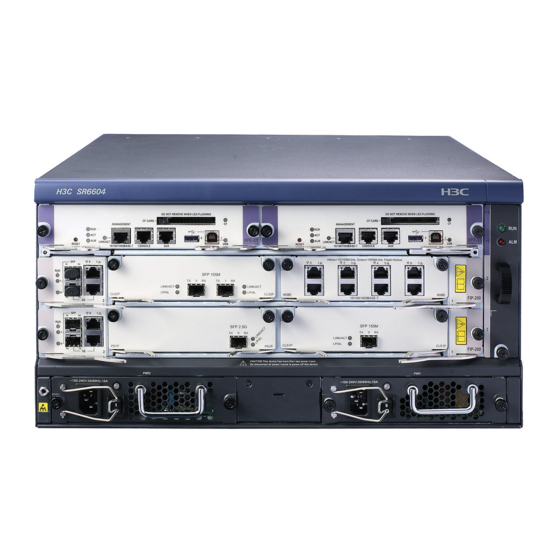
Page 100: Appendix A Chassis Views And Technical Specifications
(4) Power module slots NOTE: • The SR6604 router installed with RPE-X3, RPE-X5, or RPE-X5E MPUs has the same front view as installed with RPE-X1 MPUs. • Before installing an RPE-X1, RPE-X3, RPE-X5, or RPE-X5E MPU, install a compatible carrier in... - Page 101 Figure 94 SR6604 front view (an RSE-X1 MPU installed) (1) MPU slot (slot 1) (2) MPU/service module/switching fabric module slot (slot 2) (3) Service module/switching fabric module slot (slot 3) (4) Power module slots (5) Fan tray Figure 95 SR6604 front view (an MCP-X1 installed)
-
Page 102: Sr6608
Figure 96 SR6604 front view (an MCP-X2 installed) (1) MPU slot (slot 1) (2) MPU/service module/switching fabric module slot (slot 2) (3) Service module/switching fabric module slot (slot 3) (4) Power module slots (5) Fan tray Figure 97 SR6604 rear view... - Page 103 Figure 98 SR6608 front view (an RPE-X1 MPU installed) (1) MPU slot (slot 0 and slot 1) (2) Service module/switching fabric module slots (slot 2 through slot 5) (3) Fan tray (4) Power module slots NOTE: • The SR6608 router installed with RPE-X3, RPE-X5, or RPE-X5E MPUs has the same front view as installed with RPE-X1 MPUs.
- Page 104 Figure 99 SR6608 front view (an RSE-X1 MPU installed) (1) MPU slot (slot 1) (2) MPU/service module/switching fabric module slot (slot 2) (3) Service module/switching fabric module slot (slot 3 through slot 5) (4) Power module slots (5) Fan tray Figure 100 SR6608 front view (an MCP-X1 installed) (1) MPU slot (slot 1) (2) MPU/Service module/switching fabric module slot (slot 2)
- Page 105 Figure 101 SR6608 front view (an MCP-X2 installed) (1) MPU slot (slot 1) (2) MPU/Service module/switching fabric module slot (slot 2) (3) Service module/switching fabric module slots (slots 3 through 5) (4) Power module slots (5) Fan tray Figure 102 SR6608-DS front view (1) MPU slots (slots 0 and 1) (2) Switching fabric module slot (slot 2) (3) Service module/switching fabric module slot (slot 3)
- Page 106 IMPORTANT: • An SFE-L2 switching fabric module is provided with the SR6608-DS router. As a best practice, install the module in slot 2. For the installation procedure, see "Installing a SAP/OAP/switching fabric module." • To install an SFE-L2 switching fabric module in slot 3 on the SR6608-DS router, first install an SFU carrier in the slot.
-
Page 107: Dimensions And Weights
(3) Grounding terminal and sign (4) Air vents Dimensions and weights Table 21 Dimensions and weights Specification Item SR6604 SR6608 Height (H) 220 mm (8.66 in) (5 RU) 308 mm (12.13 in) (7 RU) Width (W) 436 mm (17.17 in) 436 mm (17.17 in) -
Page 108: Power Consumption
Model Net weight Dimensions (H × W × D) RT-BKEE 44.1 × 376.6 × 414.8 mm (1.74 × 14.83 × 16.33 in) RSE-X1 3.4 kg (7.5 lb) 45 × 399 × 412 mm (1.77 × 15.71 × 16.22 in) MCP-X1 3.5 kg (7.72 lb) 45 ×... -
Page 109: Power Modules
79.3 W 96.38 W Table 25 Fan power consumption Model Power consumption SR6604 fan tray 28.30 W to 35.20 W SR6608 fan tray 28.90 W to 36.11 W Power modules The router supports hot-swappable AC and DC power modules, but an AC power module and a DC power module cannot work together. -
Page 110: Ac Power Modules
AC power modules PSR650-A Figure 105 PSR650-A view (1) AC-input power receptacle (2) Power switch (3) Handle (4) Power module status LED Table 26 PSR650-A specifications Item Specification Rated input voltage 100 VAC to 240 VAC @ 50 or 60 Hz Maximum input current 10 A Maximum power... -
Page 111: Dc Power Modules
Item Specification Maximum power 1213 W DC power modules PSR650-D Figure 107 PSR650-D view (1) DC-input terminal block (2) Power switch (3) Handle (4) Power module status LED Table 28 PSR650-D specifications Item Specification Rated input voltage –48 VDC to –60 VDC Maximum input current 25 A Maximum power... -
Page 112: Fan Trays
Maximum input current 42 A Maximum power 1213 W Fan trays The fan tray structures of the SR6604 and SR6608 are similar. Figure 109 SR6604 fan tray Figure 110 SR6608 fan tray (1) Fan tray status LED (RUN) (2) Alarm LED (ALM) -
Page 113: Mpus
Table 30 Fan tray specifications Specification Fan (built-in) SR6604 SR6608 Rated voltage 12 VDC Automatic fan speed Supported adjustment 136.4 × 31 × 427.8 mm (5.37 ×1.22 × 228 × 31 × 413.3 mm (8.98 ×1.22 × Dimensions (H × W × D) 16.84 in) -
Page 114: Rpe-X3
Table 31 RPE-X1 specifications Item Specification Flash 4 MB • Default—One 1-GB DDR2 SDRAM Memory type and size • Maximum—Two 1-GB DDR2 SDRAMs NVRAM 128 KB Console port 9600 bps (default) to 115200 bps AUX port 9600 bps (default) to 115200 bps Management Ethernet port 1 (10Base-T/100Base-TX/1000Base-T) •... -
Page 115: Rpe-X5
Table 32 RPE-X3 specifications Item Specification Flash 8 MB • Default—One 1-GB DDR2 SDRAM Memory type and size • Maximum—Two 1-GB DDR2 SDRAMs NVRAM 128 KB Console port 9600 bps (default) to 115200 bps Supports switching to AUX port USB console port Management Ethernet port 1 (10Base-T/100Base-TX/1000Base-T) USB port... -
Page 116: Rpe-X5E
Item Specification DDR4 SDRAM Memory type and size Default: 4 GB Console/AUX port 1, 9600 bps (default) to 115200 bps Management Ethernet port 1 (10Base-T/100Base-TX/1000Base-T) USB port 1 USB 3.0 port (Host mode, Type A connector) Hot swapping Supported NOTE: SDRAM stores running configuration and buffers data during data forwarding. -
Page 117: Rse-X1
Item Specification Hot swapping Supported NOTE: SDRAM stores running configuration and buffers data during data forwarding. RSE-X1 Figure 115 RSE-X1 MPU (1) Reset button (RESET) (2) CF card button (3) CF card (4) CF card LED (5) Host-mode USB port 0 (0) (6) Device-mode USB port 1 (1) (8) LINK/ACT LED for the Ethernet management (7) USB 1 LED... -
Page 118: Mcp-X1/Mcp-X2
Item Specification Dimensions (H × W × D) 45 × 399 × 412 mm (1.77 × 15.71 × 16.22 in) Power consumption 75 W Hot swapping Supported MCP-X1/MCP-X2 Figure 116 MCP-X1 (1) Combo interface 1 (2) Combo interface 3 (3) CF card slot (CF CARD) (4) CF card LED (CF) (5) Management Ethernet port (MANAGEMENT) (6) Console port (CONSOLE) -
Page 119: Components
Table 36 MCP specifications Item Specification Flash 8 MB • MCP-X1 Default—One 2-GB DDR3 SDRAM Maximum—Two 2-GB DDR3 SDRAMs Memory type and size • MCP-X2 Default—Two 2-GB DDR3 SDRAMs Maximum—Two 2-GB DDR3 SDRAMs NVRAM 128 KB 10 Mbps, half/full-duplex Copper ports (automatic MDI/MDI-X) Combo interfaces 100 Mbps, half/full-duplex 1000 Mbps, full-duplex... - Page 120 IMPORTANT: • Use CF cards provided by H3C only. The router might be incompatible with other CF cards. • CF cards less than 256 MB are not supported. Console port The router provides an RS232 asynchronous serial console port that can be connected to a computer for system debugging, configuration, maintenance, management, and host software loading.
- Page 121 Item Specification Connects the serial port of a remote PC through a pair of modems to establish a Services dial-up connection with the PC NOTE: The dialup function for an AUX port is supported only on Comware 5. For MPU and Comware compatibility, see "MPU and Comware compatibility matrix."...
- Page 122 NOTE: • The media dependent interface (MDI) standard is typically used on the Ethernet port of network adapters. The media dependent interface crossover (MDI-X) standard is typically used on hubs or LAN switches. • For a combo interface, you can use either the copper port or the fiber port. To switch between the copper and fiber ports, use the combo enable { copper | fiber } command in interface view.
-
Page 123: Switching Fabric Modules
• If you press the RESET button when only one MPU is equipped, the whole system will be reset. • To perform an active/standby switchover when two MPUs are equipped, press the RESET button on the active MPU. The system automatically switches the services to the standby MPU, without interrupting the ongoing services. -
Page 124: Sfe-L1
SFE-L1 Front panel Figure 118 SFE-L1 front panel (1) Captive screw (2) Ejector lever (3) Switching fabric module status LED (RUN) Technical specifications Table 44 SFE-L1 specifications Item Specification DDR2 SDRAM Memory type and size 2 GB NVRAM 128 KB Hot swapping Supported Compatible device models... -
Page 125: Flexible Interface Platform Modules
Flexible interface platform modules IMPORTANT: Use transceiver modules for the service modules provided by H3C only. The router might be incompatible with transceiver modules from other vendors. The system generates an alarm when a transceiver module from another vendor is installed. -
Page 126: 117
Table 46 References for FIP operations Operation Reference Install and remove the FIP "Installing a FIP module" and "Replacing a FIP module." "Installing a HIM/MIM/MIC/MIC-X interface module" and "Replacing a Install and remove MIMs HIM/MIM/MIC/MIC-X." Connect network cables "Connecting an Ethernet cable."... -
Page 127: 118
Technical specifications Item Specification 2 HIMs supported 2 MIMs supported Not supported Hot swapping Supported Interface module slot FIP-110 You can plug up to four MIMs into the FIP-110 to provide high-density narrowband aggregation and protect the investment in the MIMs for MSR routers. Front panel Figure 122 FIP-110 front panel (1) Slot 4... -
Page 128: 119
Item Specification 10 Mbps, half/full-duplex 2 copper ports (automatic Combo interfaces 100 Mbps, half/full-duplex MDI/MDIX) 1000 Mbps, full-duplex 2 fiber ports 1000 Mbps, full-duplex Not supported 4 MIMs supported at the same time Not supported Hardware encryption Supported Power consumption 75 W Hot-swapping Supported... - Page 129 Front panel Figure 123 FIP-210 front panel (1) Combo interface 1 (2) Combo interface 0 (3) Slot 1 (4) Slot 2 (5) OPEN BOOK mark The OPEN BOOK mark indicates that the operator must read the following chapters before working with the FIP: Table 51 References for FIP operations Operation...
-
Page 130: 121
FIP-240 The FIP-240 provides two combo interfaces. It supports HIMs, MIMs, or a mix of HIMs and MIMs. Front panel Figure 124 FIP-240 front panel (1) Slot 4 (2) Slot 3 (3) Combo interface 1 (4) Combo interface 0 (5) Slot 1 (6) Slot 2 Technical specifications Item... -
Page 131: 122
Combo interface specifications Specifications of combo interfaces on the FIP-240 and the FIP-110 are the same. For more information, see Table 49 Table FIP-260 A FIP-260 provides four MIC-X interface module slots. Front panel Figure 125 FIP-260 front panel (1) Captive screw (2) Slot 4 (3) Slot 3 (4) Ejector lever... -
Page 132: 123
Front panel Figure 126 FIP-300 front panel (1) HIM/MIM slot (2) GE0 through GE11 copper port status LEDs (3) GE0 through GE11 fiber ports (4) RUN LED (5) GE0 through GE11 copper ports (6) Ejector lever (7) Captive screw Technical specifications Item Specification Flash... - Page 133 Front panel Figure 127 FIP-310 front panel (1) Combo interface 1 (2) Combo interface status LED (3) Combo interface 3 (4) SFP+ port 0 (5) SFP+ port 1 (6) RUN LED (7) SFP+ port 1 status LED (8) SFP+ port 0 status LED (9) Combo interface 2 (10) Combo interface 0 (11) HIM/MIM slot...
-
Page 134: 125
10GE port specifications Table 52 FIP-310 10GE port specifications Item Specification Connector Transceiver module type SFP+ Interface standards 802.3ae Duplex mode 10 Gbps, full duplex FIP-380 A FIP-380 delivers high-speed service processing capability. It provides two 10GBASE-R-SFP+ ports, fourteen 1000BASE-X-SFP ports, and eight 100/1000BASE-T copper ports. It supports MIC-X interface modules. -
Page 135: 126
Item Specification MIC-X A maximum of 2 Hardware encryption Supported Hot swapping Supported 10GBASE-R-SFP+ port specifications Table 53 FIP-380 10GBASE-R-SFP+ port specifications Item Specification Connector Transceiver module type SFP+ Interface standards 802.3ae Duplex mode 10 Gbps, full duplex 1000BASE-X-SFP port specifications Table 54 FIP-380 1000BASE-X-SFP port specifications Item Specification... -
Page 136: 127
Front panel Figure 129 FIP-600 front panel (1) Combo interface 1 (2) Combo interface 0 (3) Slot 1 (4) Slot 2 (5) OPEN BOOK mark Technical specifications Item Specification Flash 8 MB • Default—Two 2-GB DDR3 SDRAMs • Maximum—Two 2-GB DDR3 SDRAMs Memory type and size The SDRAMs must be used in pairs and must be the same size. -
Page 137: 128
Front panel Figure 130 FIP-660 front panel (1) Captive screw (2) Slot 4 (3) Slot 3 (4) Ejector lever (5) Slot 1 (6) Slot 2 Air deflector Figure 131 FIP-660 air deflector Technical specifications Item Specification Memory type and size 16GB DDR4 Drive Not supported... - Page 138 Front panel Figure 132 FIP-680 front panel (1) Interface module slot (2) 10GBASE-R-SFP+ ports (4 in total) (3) 1000BASE-X-SFP ports (12 in total) (4) 10/100/1000BASE-T copper Ethernet ports (8 in total) (5) Module status LED (RUN) (6) 10/100/1000BASE-T copper Ethernet port status LED Technical specifications Item Specification...
-
Page 139: Service Aggregation Platform Modules
{ copper | fiber } command, see H3C SR6600/SR6600-X Routers Interface Command Reference(V7). A service aggregation platform (SAP) module provides network ports for receiving packets from the network and sending packets to the network. This section describes the SAPs available for the H3C SR6604 and SR6608 routers. SAP-48GBE The SAP-48GBE has 48 high-performance RJ-45 ports that can be both routed and switched. -
Page 140: Sap-24Gbp
Front panel Figure 133 SAP-48GBE front panel (1) LEDs for GE ports 0 to 47 (2) SAP module status LED (RUN) (3) GE ports 0 to 47 (4) Ejector levers (5) Captive screw Technical specifications Item Specification Flash 4 MB •... -
Page 141: Sap-48Gbp
Front panel Figure 134 SAP-24GBP front panel (1) SFP ports 0 to 23 (2) SAP module status LED (RUN) (3) LEDs for SFP ports 0 to 23 (4) Ejector levers (5) Captive screw Technical specifications Item Specification Flash 4 MB •... - Page 142 Front panel Figure 135 SAP-48GBP front panel (1) SFP ports 0 to 47 (2) SAP module status LED (RUN) (3) LEDs for SFP ports 0 to 47 (4) Ejector levers (5) Captive screw Technical specifications Item Specification Flash 4 MB •...
-
Page 143: Sap-20Ge2Xp
SAP-20GE2XP Front panel Figure 136 SAP-20GE2XP front panel (1) SFP ports (GE0 to GE15) (2) Combo interfaces (GE16 to GE19) (3) SFP+ port 0 (4) SFP+ port 1 (5) Operating status LED (RUN) Technical specifications Item Specification Flash 8 MB. •... -
Page 144: Sap-28Ge
Item Specification Interface type Auto MDI/MDI-X • Ethernet_II Frame format supported • Ethernet_SNAP 10 Mbps auto-sensing Half/full duplex, auto-negotiation Interface speed and duplex 100 Mbps auto-sensing Half/full duplex, auto-negotiation mode 1000 Mbps auto-sensing Full duplex, auto-negotiation For the fiber combo port specifications, see Table Table 61 SFP+ port specifications Item... - Page 145 Item Specification • Copper port—Straight-through/crossover autosensing: Combo interfaces 10/100 Mbps, half/full-duplex. 1000 Mbps, full-duplex. • Fiber port—1000 Mbps, full-duplex. Hot swapping Supported. Fixed Ethernet port specifications Table 62 SFP port specifications Item Specification Connector type Transceiver module type Network synchronization Supported 1588v2.2 protocol Supported...
-
Page 146: Sap-Xp4Ge32
SAP-XP4GE32 Front panel Figure 138 SAP-XP4GE32 front panel (1) Captive screw (2) 10/100/1000Base-T Ethernet copper ports GE0 to GE11 (3) Combo interfaces GE12 to GE23 (4) 1000BASE-X-SFP ports SFP24 to SFP31 (5) 10GBASE-R-SFP+ ports SFP+32 to SFP+35 (6) Operating status LED (RUN) (7) Ejector lever Technical specifications Item... -
Page 147: Transceiver Modules
For the fiber combo port specifications, see Table Transceiver modules For more information about transceiver modules supported by the SR6604 and SR6608 switches, see H3C SR6600/SR6600-X Routers Interface Module Guide. Lightning protector for a port Port protective unit–single port, maximum discharge current (8/20μs waveform): 5 kA, output voltage (10/700μs waveform): core-core <... -
Page 148: Surge Lightning Protector
Maximum discharge current: 6500 A, protection voltage: 500 VAC to 220 VAC. For how to install the power lightning protector, see "Connecting the AC power supply to a power strip with lightning protection." Surge lightning protector Generally, you need to connect a surge protector before connecting a signal cable to the router. This can protect electronic devices against surge over-voltage resulting from lightning strokes and other interferences, and minimize impact on the router. -
Page 149: Appendix B Hardware Compatibility Matrixes
Appendix B Hardware compatibility matrixes In the compatibility matrixes, "√" means "Supported" and "×" means "Not supported." MPU and Comware compatibility matrix Table 67 MPU and Comware compatibility matrix Comware 5 Comware 7 RPE-X1 √ × RPE-X3 × √ RPE-X5 ×... -
Page 150: Interface Module And Comware Compatibility Matrix
Service RPE-X1 RPE-X3 RPE-X5 RPE-X5E RSE-X1 MCP-X1 MCP-X2 module SAP-20GE2XP × √ × × × × × SAP-28GE × √ × × × × × SAP-XP4GE32 × √ √ √ × × × SPE-FWM-200 √ × × × √ × ×... -
Page 151: Appendix C Leds
Appendix C LEDs The MPUs, switching fabric modules, FIPs, SAPs, HIM/MIM/MICs, power modules, and fan trays available for the router provide various LEDs to indicate the operating status. Table 70 H3C SR6604 and SR6608 routers LEDs Remarks Run LED (RUN) -
Page 152: Mpu Leds
1000 Mbps fiber Ethernet port LED (SFP0 and SFP1) Run LED (RUN) Table 87 SAP LEDs Table 10/100/1000 Mbps Ethernet port LED HIM/MIM/MIC/ See H3C SR6600/SR6600-X Routers Interface Module Guide. MIC-X LEDs Power module LEDs Power LED Table Run LED (RUN) Fan tray LEDs... - Page 153 Figure 139 LEDs on the RPE-X1 Table 71 RPE-X1 LED description Status Description No power input is available, or the RPE-X1 has failed. Slow flashing (1 The RPE-X1 is operating correctly. (green) The application software is being loaded (in this case, Fast flashing (8 never power off the device or hot-swap the RPE-X1;...
- Page 154 Figure 140 RPE-X3 LEDs Table 72 RPE-X3 LED description Status Description Steady yellow A 10/100 Mbps link is present. Steady green A 1000 Mbps link is present. LINK/ACT Flashing yellow Data is being received or transmitted at 10/100 Mbps. (yellow/green) Flashing green Data is being received or transmitted at 1000 Mbps.
- Page 155 Figure 141 LEDs on the RPE-X5 Table 73 RPE-X5 LED description Status Description Fast flashing The BIOS is operating correctly. green Slow flashing No or insufficient memory or initialization yellow failure. BIOS stage Fast flashing The extended segment does not exist. yellow Hardware failure or no power input.
- Page 156 Status Description Steady green A 1000 Mbps link is present. Flashing green Data is being received or transmitted at 1000 Mbps. MANAGEME Steady yellow A 100 Mbps link is present. (yellow/green) Flashing yellow Data is being received or transmitted at 100 Mbps. No link is present or the port is faulty.
- Page 157 Hardware failure or no power input. Slow flashing The system is operating correctly. green Comware Fast flashing stage USB-based automatic configuration green (5 has succeeded. seconds) Steady on The system power is insufficient. PALM The power system is operating correctly. (red) Slow flashing The device is in IRF mode and the MPU is the global...
- Page 158 Steady red The shutdown of the Comware system is in progress. The Comware system has shut down. Figure 143 RSE-X1 LEDs Table 75 RSE-X1 LED description Status Description No CF card is present or the CF card is not recognizable. Steady on A CF card is in position and has been detected.
- Page 159 The system is accessing the CF card. In this Flashing green (yellow/green) state, do not remove the CF card. Steady yellow A CF card not provided by H3C. No power input is available, or the MCP-X1 has failed. Slow flashing (1 The MCP-X1 is operating correctly.
- Page 160 Steady green A CF card is in position and has been detected. The system is accessing the CF card. In this state, Flashing green (yellow/green) do not remove the CF card. Steady yellow A CF card not provided by H3C.
- Page 161 Status Description No power input is available, or the MCP-X1 has failed. Slow flashing The MCP-X1 is operating correctly. (1 Hz) (green) The application software is being loaded (in this Fast flashing case, never power off the device or hot-swap the (8 Hz) MCP-X1;...
-
Page 162: Switching Fabric Module Leds
Switching fabric module LEDs Figure 146 SFE-L1 status LED Figure 147 SFE-L2 status LED Table 78 SFE-L1 LED description Status Description No link is present or the module is faulty. Slow flashing (1 The module is operating correctly. Application software is being loaded. (green) Fast flashing (8 To avoid damage to the module, do not power off... - Page 163 Figure 149 FIP-20 status LED Table 79 FIP-10/20 LED description Status Description No link is present or the FIP is faulty. Slow flashing (1 The FIP is operating correctly. System software is being loaded. To avoid damage (green) Fast flashing (8 to the FIP, never power off the device or hot-swap the FIP while the system software is being loaded.
- Page 164 Figure 152 FIP-240 LEDs Figure 153 FIP-600 LEDs Table 80 FIP-110/210/240/600 LED description Status Description No link is present. Steady green A 1000 Mbps link is present. 10/100/1000 Mbps copper Flashing green Data is being received or transmitted at 1000 Mbps. Ethernet port Steady yellow A 10/100 Mbps link is present.
- Page 165 Figure 154 FIP-260 LEDs Table 81 FIP-260 LED description Status Description No power input is available or the FIP-260 has failed. Fast flashing (8 System software is being loaded. Steady green The FIP software system is starting up. (green) Slow flashing (1 The FIP is operating correctly.
- Page 166 Figure 156 FIP-310 LEDs Table 83 FIP-310 LED description Status Description No link is present. Steady green A 1000 Mbps link is present. GE0 through Flashing green Data is being received or transmitted at 1000 Mbps. Steady yellow A 10/100 Mbps link is present. (yellow/green) Flashing yellow Data is being received or transmitted at 10/100 Mbps.
- Page 167 Table 84 FIP-380 LED description Status Description No link is present or the port has failed. Steady yellow A 1000 Mbps link is present. Flashing yellow SFP+22 and Data is being received or transmitted at 1000 Mbps. (8 Hz) SFP+23 Steady green A 10 Gbps link is present.
- Page 168 Table 85 FIP-660 LED description Status Description No power input is available or the FIP-660 has failed. Fast flashing (8 System software is being loaded. Steady green The FIP software system is starting up. (green) Slow flashing (1 The FIP is operating correctly. Figure 159 FIP-680 LEDs Table 86 FIP-680 LED description Status...
-
Page 169: Sap Leds
SAP LEDs Figure 160 SAP LEDs(SAP-48GBE) Table 87 SAP-48GBE LED description Item Status Description No link is present. Steady green A 1000 Mbps link is present. Status LEDs of Flashing green Data is being received or transmitted at 1000 Mbps. GE 0 through Steady yellow... - Page 170 Status Description No link is present. Steady green A 1000 Mbps link is present. Status LEDs of SFP 0 to Flashing green Data is being received or transmitted at 1000 Mbps. SFP 23 (yellow/green) Steady yellow A 100 Mbps link is present. Flashing yellow Data is being received or transmitted at 100 Mbps.
- Page 171 Table 90 SAP-20GE2XP LED description Status Description No power input is available or the SAP-20GE2XP has failed. Slow flashing (1 The SAP-20GE2XP is operating correctly. System software is being loaded or the SAP-20GE2XP is not operating. (green) CAUTION: Fast flashing (8 To avoid hardware damage, do not power off the router, or insert or remove the SAP-20GE2XP when system software is being...
- Page 172 Figure 164 SAP-28GE LEDs Table 91 SAP-28GE LED description Status Description No power input is available or the SAP-28GE has failed. Slow flashing (1 Hz) The SAP-28GE is operating correctly. System software is being loaded or the SAP-28GE is not operating. (green) CAUTION: Fast flashing (8 Hz)
- Page 173 Figure 165 SAP-XP4GE32 LEDs Table 92 SAP-XP4GE32 LED description Status Description No power input is available or the port has failed. • GE0 through Steady yellow A 10/100 Mbps link is present. GE11 Data is being received or transmitted • Flashing yellow (8 Hz) GE12 through at 10/100 Mbps.
-
Page 174: Him/Mim/Mic/Mic-X Leds
HIM/MIM/MIC/MIC-X LEDs For HIM/MIM/MIC/MIC-X LED description, see H3C SR6600/SR6600-X Routers Interface Module Guide. Power module LEDs Figure 166 PSR650-A AC power module LED Figure 167 PSR1200-A AC power module LED Figure 168 PSR650-D DC power module LED Figure 169 PSR1200-D DC power module LED... -
Page 175: Fan Tray Leds
Power LED Steady red The power module is faulty. No power is input. Fan tray LEDs Figure 170 Fan tray for the SR6604 Figure 171 Fan tray for the SR6608 Table 94 Fan tray LED description Status Description The system is powered off or the fan tray is faulty. - Page 176 Status Description The fan tray is operating correctly. Steady on The fan tray is faulty. (red)
-
Page 177: Appendix D Arranging Slots And Numbering Interfaces
The router provides multiple types of ports, including console port, AUX port, GigabitEthernet port, serial (synchronous) port, POS port, and E1 port. Figure 172 Slot arrangement on the SR6604 configured with an RPE-X1/RPE-X3/RPE-X5/RPE-X5E MPU Figure 173 Slot arrangement on the SR6604 configured with an RSE-X1 or MCP-X1/X2 MPU... - Page 178 Figure 174 Slot arrangement on the SR6608 configured with an RPE-X1/RPE-X3/RPE-X5/RPE-X5E MPU Figure 175 Slot arrangement on the SR6608 configured with an RSE-X1 or MCP-X1/X2 MPU NOTE: • The numbers in Figure 172 through Figure 175 represent corresponding slot numbers. •...
-
Page 179: Slot Arrangement For Mpus, Switching Fabric Modules, And Service Modules
Table 95 Slot arrangement for MPUs, switching fabric modules, and service modules MPUs, switching fabric Slot arrangement on the Slot arrangement on the modules, and service SR6604 SR6608 modules MPUs RPE-X1/RPE-X3/RPE-X5/ Slot 0 and slot 1 RPE-X5E (supporting 1+1 An SR6608-DS router does not support the RPE-X1 MPU. -
Page 180: Examples
• interface-type—Type of the interface such as GE port and serial port. • X—Number of the slot where the FIP/SAP resides, in the range of 2 to 3 on the SR6604 and 2 to 5 on the SR6608. • Y—Number of the slot where the HIM/MIM/MIC/MIC-X resides on the FIP. For a SAP, the subslot number is 0. -
Page 181: Index
Index A C D E F G H I L M N P R S T Installing a CF card,26 Installing a fan tray,25 Accessing the router from the console port,50 Installing a fiber management tray,31 Installing a FIP module and an air deflector,20 Installing a HIM/MIM/MIC/MIC-X interface Chassis... - Page 182 Replacing a memory module,75 Service aggregation platform modules,130 Replacing a power module,66 Service module and MPU compatibility matrix,140 Replacing a SAP/OAP/switching fabric module,70 Slot arrangement,168 Replacing a transceiver module,73 Slot arrangement for MPUs, switching fabric modules, and service modules,170 Replacing an air filter,74 Software upgrade failures,89...
Need help?
Do you have a question about the SR6604 and is the answer not in the manual?
Questions and answers