
Related Manuals for H3C SR6602


Summary of Contents for H3C SR6602
-
Page 1: Installation Guide
H3C SR6602 Router Installation Guide Hangzhou H3C Technologies Co., Ltd. http://www.h3c.com Document version: T2-08040E-20110810-C-1.09... - Page 2 SecPro, SecPoint, SecEngine, SecPath, Comware, Secware, Storware, NQA, VVG, V G, V G, PSPT, XGbus, N-Bus, TiGem, InnoVision and HUASAN are trademarks of Hangzhou H3C Technologies Co., Ltd. All other trademarks that may be mentioned in this manual are the property of their respective owners Notice The information in this document is subject to change without notice.
- Page 3 Preface The H3C SR6602 Router Installation Guide includes seven chapters, which describe the hardware features of the H3C SR6602 Router and provide examples to help you install the router. This preface includes: Audience • • Conventions About the H3C SR6600 documentation set •...
- Page 4 Layer 2 forwarding and other Layer 2 features. Port numbering in examples The port numbers in this document are for illustration only and might be unavailable on your device. About the H3C SR6600 documentation set The H3C SR6600 documentation set includes: Category...
-
Page 5: Obtaining Documentation
Obtaining documentation You can access the most up-to-date H3C product documentation on the World Wide Web at http://www.h3c.com. Click the links on the top navigation bar to obtain different categories of product documentation: [Technical Support & Documents > Technical Documents] –... -
Page 6: Table Of Contents
Contents Product overview·························································································································································· 1 Front panel view································································································································································1 Rear panel view ································································································································································1 Preparing for installation ············································································································································· 2 Safety recommendations ··················································································································································2 Safety symbols ··························································································································································2 General safety recommendations ···························································································································2 Safety with electricity ···············································································································································2 Safety with laser ·······················································································································································2 Examining the installation site ·········································································································································3 Temperature and humidity·······································································································································3 Altitude ······································································································································································3 Cleanness ··································································································································································3 Cooling system ·························································································································································4... - Page 7 Logging in to the router and configuring basic settings ··························································································26 Login methods································································································································································· 26 Logging in through the console port ···························································································································· 26 Setting up a configuration environment ·············································································································· 26 Creating a hyperterminal connection and setting terminal parameters ·························································· 27 Powering on the router ·················································································································································· 30 Checking before power-on···································································································································...
- Page 8 User password loss ··············································································································································· 53 Super password loss ············································································································································· 54 Cooling system failure ··················································································································································· 55 Interface module, cable, and connection failure ········································································································ 55 Appendix A Technical specifications························································································································57 Dimensions and weight ················································································································································· 57 Storages ·········································································································································································· 57 AC power supply ··························································································································································· 57 RPS power supply (optional) ·········································································································································...
-
Page 9: Product Overview
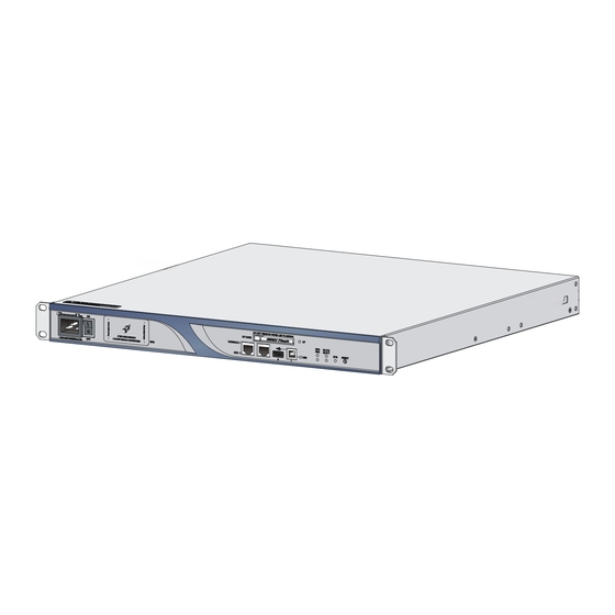
Product overview This chapter describes the H3C SR6602 router and includes these sections: Front panel view • Rear panel view • Front panel view Figure 1 Front panel view (1) AC-input power receptacle (100 VAC to 240 VAC, (2) AC power switch (ON/OFF) 50 or 60 Hz at 2.5 A) -
Page 10: Preparing For Installation
Preparing for installation This chapter includes these sections: Safety recommendations • Examining the installation site • Installation tools • • Installation accessories Checklist before installation • Safety recommendations Safety symbols When reading this document, note the following symbols: WARNING means an alert that calls attention to important information that if not understood or followed can result in personal injury. -
Page 11: Examining The Installation Site
Install a dust plug on the transceiver module to avoid damage to the transceiver module. • Examining the installation site The H3C SR6602 router can only be used indoors. To ensure that the router works properly and to prolong its service lifetime, the installation site must meet the following requirements: Temperature and humidity •... -
Page 12: Cooling System
0.006 0.05 0.01 Cooling system The H3C SR6602 router adopts left to right airflow for heat dissipation. Figure 3 SR6602 airflow Make sure there is enough space (greater than 10 cm (3.94 in)) around the air intake and outlet •... -
Page 13: Emi
Check the resistance of the ESD-preventive wrist strap for safety. The resistance reading should be in the range of 1 to 10 megohm (Mohm) between human body and the ground. No ESD-preventive wrist strap is provided with the H3C SR6602 router. Prepare it yourself. •... -
Page 14: Lightning Protection
NOTE: Use electromagnetic shielding when necessary. Lightning protection To protect the router from lightning better, do as follows: Make sure the grounding cable of the chassis is well grounded. • Make sure the grounding terminal of the AC power receptacle is well grounded. •... -
Page 15: Installation Accessories
Installation accessories Rear mounting Front mounting Console cable Grounding cable bracket and bracket and M4 Rubber pads load-bearing screw screws ESD-preventive M6 screws Cage nuts Cable tie wrist strap Checklist before installation Table 6 Checklist before installation Item Requirements Result •... - Page 16 Item Requirements Result • The grounding cable of the chassis is well grounded. • The grounding terminal of the AC power receptacle is well grounded. • A port lightning arrester is installed. (Optional) Lightning protection • A power lightning arrester is installed. (Optional) •...
-
Page 17: Installing The Router
Installing a power lightning arrester (lightning protection busbar) (optional) • Installing a signal lightning arrester (optional) • • Connecting an AC power cord Connecting an RPS DC power cord • • Verifying the installation Installation flow Figure 5 H3C SR6602 router installation flow... -
Page 18: Installing The Router In A 19-Inch Rack
Installing the router in a 19-inch rack Installing cage nuts and rear mounting brackets to the rack Follow these steps to install cage nuts to the rack: As shown in Figure 6, mark the positions of cage nuts on the front rack posts by using a front mounting Step1 bracket, and then mark the positions of cage nuts on the rear rack posts at the same level by using a rear mounting bracket. -
Page 19: Installing Front Mounting Brackets To The Router
Figure 8 Install rear mounting brackets to the rack Installing front mounting brackets to the router Before installing the router to a rack, install the front mounting brackets to the two sides of the router. To install the front mounting brackets to the router, align the screw holes on the mounting brackets with the screw holes on the router chassis, and then use a Phillips screwdriver to fasten the screws. -
Page 20: Installing The Router To The Rack
Figure 10 Install screws for mounting the router to the rear mounting brackets Installing the router to the rack Wear an ESD-preventive wrist strap, and check that the rack is sturdy. Step1 Supporting the router bottom with one hand, push the router into the rack horizontally, and make sure Step2 that the upper edges of the rear mounting brackets make close contact with the load-bearing screws on the router. -
Page 21: Grounding The Router
Figure 12 Fix the router to the rack (1) Screws for mounting the router to the rear mounting brackets Grounding the router WARNING! Correctly connecting the router grounding cable is crucial to lightning protection and EMI protection. The power input end of the router has a noise filter, whose central ground is directly connected to the chassis to form the chassis ground. -
Page 22: Installing Interface Modules
Figure 13 Connect the grounding cable to the grounding hole of router NOTE: The resistance reading should be smaller than 5 ohms between router chassis and the ground. • To guarantee the grounding effect, use the grounding cable provided with the router to connect to the •... -
Page 23: Installing A Him
NOTE: Keep the removed filler panel and screws for future use. Installing a HIM Follow these steps to install a HIM: Select the slot to install the HIM, and remove the filler panels on the slot. For how to remove a filler panel, Step1 “Removing a filler panel.”... -
Page 24: Installing A Cf Card
Figure 16 Push the MIM into the slot Use a flat-blade screwdriver to fasten the captive screws on the MIM. Step3 Power on the router and check the status LED on the front panel. On means the MIM is installed correctly Step4 and running properly. -
Page 25: Connecting Ethernet Cables
Otherwise, the router cannot be booted. Connecting Ethernet cables Connecting a copper Ethernet cable The 10/100/1000Base-T copper ports of the H3C SR6602 router support MDI/MDI-X auto-sensing. They are connected to the network through category-5 or above twisted pairs that are equipped with RJ-45 connectors. - Page 26 Figure 18 Remove the dust cover Plug one end of the optical fiber into the transceiver module in the switch, as shown in Figure Step2 Figure 19 Install the transceiver module Remove the dust cover on the transceiver module. Step3 Plug the LC connectors on one end of the fiber cable into the Rx and Tx ports, and plug the LC connectors Step4 on the other end to the Tx and Rx ports on the peer device, as shown in...
-
Page 27: Installing A Port Lightning Arrestor (Optional)
Before connecting an outdoor Ethernet cable to an Ethernet port, install a port lightning arrester to protect the router against lightning strokes. The following port lightning arrester can be installed on the SR6602. The specifications for the port lightning arrester are as follows: Port protective unit–single port, maximum discharge current (8/20μs waveform): 5 kA, output voltage (10/700μs waveform): core-core <... -
Page 28: Installing A Power Lightning Arrester (Lightning Protection Busbar) (Optional)
Precautions The performance of the port lightning arrester may be affected in the following cases: • The IN and OUT ends of the port lightning arrester are connected incorrectly. The IN end should be connected to the external cable, and the OUT end to the Ethernet port of the router. - Page 29 Figure 22 Install a power lightning arrester (1) Status LED—On means the lightning protection functions properly. Off means the lightning protection has failed. (2) Grounding and polarity detection LED (red)—On means the grounding cable is not well connected or the live and zero wires are connected reversely.
-
Page 30: Installing A Signal Lightning Arrester (Optional)
Before installing a signal lightning arrester, consider such performance indexes of the lightning arrester as lightning protection, bandwidth, transmission loss, and port type. The SR6602 supports the following types of signal lightning arresters: Voltage-limiting protection – signal lightning arrester – maximum discharge current •... -
Page 31: Connecting An Ac Power Cord
Figure 23 Install a port lightning arrester Precautions The performance of the signal lightning arrester may be affected in the following cases: • The IN and OUT ends of the signal lightning arrester are connected incorrectly. The IN end should be connected to the external cable, and the OUT end to the Ethernet port of the router. -
Page 32: Connecting An Rps Dc Power Cord
Figure 24 Connect an AC power cord to the router Connecting an RPS DC power cord NOTE: No RPS power cord is provided with the router. Prepare it yourself. RPS power receptacle The RPS power receptacle locates at the front panel, as shown in Figure Figure 25 RPS power receptacle Follow these steps to connect an RPS DC power cord:... -
Page 33: Verifying The Installation
Figure 26 Remove the protection cover Insert the RPS plug in the RPS DC receptacle of the router. Step4 Use a flat-blade screwdriver to fix the two fastening screws on the RPS plug to secure the plug to the RPS Step5 DC receptacle of the router. -
Page 34: Logging In To The Router And Configuring Basic Settings
Logging in to the router and configuring basic settings This chapter includes these sections: • Login methods Logging in through the console port • Powering on the router • Logging in to the router through Telnet • Logging to the router through the AUX port •... -
Page 35: Creating A Hyperterminal Connection And Setting Terminal Parameters
Figure 28 Connect the console cable CAUTION: When you disconnect a PC from a powered-on router, disconnect the DB-9 connector of the console cable from the PC after disconnecting the RJ-45 connector from the router. Creating a hyperterminal connection and setting terminal parameters To configure and manage the router, you must run a terminal emulator program on the configuration terminal, for example, a PC. - Page 36 Figure 30 Set the serial port used by the HyperTerminal connection Click OK after selecting a serial port and the following dialog box appears. Set Bits per second to 9600, Step3 Data bits to 8, Parity to None, Stop bits to 1, and Flow control to None. Figure 31 Set the serial port parameters Click OK after setting the serial port parameters and the system enters the following interface.
- Page 37 Figure 32 HyperTerminal window Click Properties in the HyperTerminal window to enter the aaa Properties dialog box. Click the Settings Step5 tab, set the emulation to VT100, and then click OK. Figure 33 Set terminal emulation in aaa Properties dialog box...
-
Page 38: Powering On The Router
After power-on, the following information appears on the terminal screen: System start booting... Booting Normal Extend BootWare..**************************************************************************** H3C SR6602 Router BootWare, Version 1.31 **************************************************************************** Copyright (c) 2004-2011 Hangzhou H3C Technologies Co., Ltd. Compiled Date : Jan 13 2011 CPU Type : XLR732 CPU L1 Cache... -
Page 39: Logging In To The Router Through Telnet
CPLD Version : 135.0 PCB Version : Ver.B BootWare Validating... Press Ctrl+B to enter extended boot menu... Starting to get the main application file--cfa0:/SR6602.bin!................ The main application file is self-decompressing ................................Done! System is starting..User interface con0 is available. -
Page 40: Configuring Basic Settings
Connect the AUX port to the configuration terminal by using the console cable. Then you can log in to Step2 the router through the AUX port. NOTE: H3C SR6600 Routers Configuration For more information about how to log in to the router, see the Guides Configuring basic settings Follow these steps to configure basic settings for the router: To do…... -
Page 41: Hardware Management And Maintenance
H3C Comware Platform Software Comware Software, Version 5.20, R0600 Copyright (c) 2010 Hangzhou H3C Technologies Co., Ltd. H3C SR6602 uptime is 0 week, 0 day, 0 hour, 4 minutes CPU type: RMI XLR732 1000MHz 1024M bytes DDR2 SDRAM Memory 4M bytes Flash Memory Version: Ver.B... -
Page 42: Displaying Operational Statistics Of The Router
[SLOT 1] MIM-4SAE (Hardware)2.0, (Driver)1.0, (Cpld)2.0 [SLOT 2] The SubCard is not present Displaying operational statistics of the router When you perform routine maintenance or the system fails, you may need to display the operational information of each functional module for locating failures. Generally, you need to run the display commands one by one. -
Page 43: Displaying The Electrical Label Information Of The Router
MAC address, and vendor name. <Sysname> display device manuinfo DEVICE_NAME:6602 DEVICE_SERIAL_NUMBER:4567 MAC_ADDRESS:000f-e234-4567 MANUFACTURING_DATE:2010-06-29 VENDOR_NAME:H3C Use the display device manuinfo slot slot-number command to display the electrical label information of the interface module in the specified slot. <Sysname> display device manuinfo slot 0 DEVICE_NAME:6602 DEVICE_SERIAL_NUMBER:4567... -
Page 44: Displaying The Cpu Usage Of The Router
Field Description VENDOR_NAME Vendor name The operation is not supported on The display device manuinfo command is not supported. the specified board or subslot Displaying the CPU usage of the router Use the display cpu-usage command to display the CPU usage of a router. <Sysname>... -
Page 45: Displaying The Operational Status Of The Fans
<Sysname> display device cf-card Slot No. Dev No. Status Size(M) ----------------------------------------------- Normal Absent Table 11 Output description Field Description Slot No Slot number of the CF card Device number of the CF card: • Dev No. 0 for a built-in CF card •... -
Page 46: Displaying The Temperature Alarm Thresholds For An Interface Module
Field Description The power module state: • Normal—The power module is operating properly. State • Absent—The power module is not in position. • Fault—The power module fails. Displaying the temperature alarm thresholds for an interface module When the router is operating, too high a temperature and too low a temperature will affect the normal operation of the router. -
Page 47: Displaying Transceiver Module Information And Alarming Information
If the output includes “Media type is twisted pair, Port hardware type is 1000_BASE_T”, it means • that the port is an RJ-45 Ethernet port. For example, the following output shows that GigabitEthernet 0/2 is an RJ-45 Ethernet port. [Sysname] display interface GigabitEthernet 0/2 GigabitEthernet0/2 current state: DOWN ( Administratively ) IP Packet Frame Type: PKTFMT_ETHNT_2, Hardware Address: 0000-fc00-7506 Description: GigabitEthernet0/2 Interface... -
Page 48: Solving System Faults
The system outputs alarm information for you to locate and troubleshoot faults of transceiver modules. For the H3C-customized transceiver modules, the system can also monitor the key parameters, such as temperature, voltage, laser bias current, TX power, and RX power. When these parameters are abnormal, you can take corresponding measures to prevent transceiver module faults. -
Page 49: Viewing The System Fault Solving Method
Follow these steps to solve system faults: To do… Use the command… Remarks Enter system view system-view — Optional Specify the system fault system-failure { maintain | reboot } solving method reboot by default Viewing the system fault solving method Use the display system-failure command to display the system fault solving method. - Page 50 Use the reboot command to reboot a router. • • Enable the scheduled reboot function at the CLI. You can set a time at which the router can automatically reboot, or set a delay so that the router can automatically reboot within the delay. Power on the router after powering it off, which is also called hard reboot or cold start.
-
Page 51: Replacement Procedures
Replacement procedures This chapter includes these sections: Safety recommendations • Replacing a HIM • Replacing an MIM • • Replacing a CF card Replacing a transceiver module • Replacing a memory module • Safety recommendations Always wear an ESD-preventive wrist strap or ESD-preventive gloves when maintaining the router hardware. -
Page 52: Replacing An Mim
If you do not install a new interface module in the slot, install two blank panels. To install a HIM, see Step3 “Installing the router.” Replacing an MIM Follow these steps to replace a MIM: Use a flat-blade screwdriver to loosen the captive screws of the MIM to be removed. Step1 Gently pull the MIM out of the slot along the slide rails. -
Page 53: Replacing A Transceiver Module
Figure 37 Press the eject button to eject the CF card Install a new CF card. For more information, see “Installing the router.” Step4 CAUTION: To avoid hardware damage, do not remove the CF card when the router is booting or the CF card LED •... -
Page 54: Replacing A Memory Module
An existing memory module is damaged. • CAUTION: Use the memory modules provided by H3C only. Otherwise, the router may be unable to operate • properly. Memory modules with the same capacity must be used in pairs, for the specifications of memory •... -
Page 55: Opening The Router Chassis Cover
CAUTION: Keep the tamper-proof seal on a mounting screw on the chassis cover intact, and if you want to open the chassis, contact the local agent of H3C for permission. Follow these steps to open the router chassis cover: Power off the router and unplug the power cables. - Page 56 Figure 41 Insert screwdrivers into key holes and pry the cover Facing the rear panel of the router, pull the chassis cover backward about 5 cm (1.97 in). Step4 Figure 42 Pull the chassis cover backward about 5 cm (1.97 in) Lift the end of the chassis cover and then pull the chassis cover away from the bottom part of the chassis.
-
Page 57: Memory Module Structure
Figure 43 Remove the chassis cover Memory module structure Figure 44 Structure of a memory module (a ) Front view (b ) Rear view (1) Connector edge (2) Polarization notch (3) Latch notch... -
Page 58: Memory Module Slot
Memory module slot Figure 45 Memory module slot (1) Release latch (2) Memory module slot Removing a memory module Follow these steps to remove a memory module: Make sure all power sources to the router are disconnected. Step1 Pull the release latches away from the memory module at both ends so that the memory module is lifted Step2 from the memory module slot. - Page 59 Position the memory module so that it is perpendicular to the memory module slot and insert the memory Step3 module into the memory module slot. Carefully and firmly press the memory module at both ends until you hear a click, which indicates the Step4 memory module is seated in the memory module slot.
-
Page 60: Troubleshooting
Keep the tamper-proof seal on a mounting screw on the chassis cover intact, and if you want to open the chassis, contact the local agent of H3C for permission. Otherwise, H3C shall not be liable for any consequence caused thereby. -
Page 61: Configuration Terminal Problems
If the cause cannot be located in the steps above and the problem persists, contact your local sales agent. Configuration terminal problems If the configuration environment setup is correct, the configuration terminal displays boot information when the router is powered on. If the setup is incorrect, the configuration terminal displays nothing or garbled text. -
Page 62: Super Password Loss
NOTE: To save the new password, execute the save command after modifying the user password. • H3C recommends saving the modification as the default configuration file. • Super password loss The super password enables you to switch between four super levels. In the case of super password loss, you cannot perform higher level operations. -
Page 63: Cooling System Failure
%Jun 28 10:27:27:653 2010 H3C DRVMSG/3/Temp2High: Environment temperature too high in Slot 0, index is 1. #Jun 28 10:27:28:432 2010 H3C DEV/1/BOARD TEMPERATURE UPPER: Trap 1.3.6.1.4.1.2011.2.23.1.12.1.16<hwBoaardTemperatureHigher>:frameIndex is 0, slotIndex 0.0 %Jun 28 10:27:28:433 2010 H3C DEV/4/BOARD TEMP TOOHIGH: Board temperature is too high on Frame 0 Slot 0, type is RPU. - Page 64 Check whether the HIM/MIM cable is correctly selected. Step1 Check whether the HIM/MIM cable is correctly connected. Step2 Use the display command to check whether the interface has been correctly configured and is working Step3 properly.
-
Page 65: Appendix A Technical Specifications
Appendix A Technical specifications Dimensions and weight Table 15 Dimensions and weight Item Specification 44 mm (1.73 in), which is approximately one rack Height (H) unit (RU) Width (W) 442 mm (17.40 in) Depth (D) 460 mm (18.11 in) Weight 7.5 kg (16.53 lb) Storages Table 16 Processor and storages... -
Page 66: Power Consumption Range
The SR6602 supports AC power input and RPS input. They can guarantee the router to continue working when one power supply fails, providing high reliability. Table 18 RPS power specifications Item Specification Rated output voltage 12 V Maximum output current... -
Page 67: Aux Port
Item Specification Transmission distance ≤15 m (49.21 ft) Provides connection to an ASCII terminal Provides connection to the serial port of a local PC to run the terminal emulation Services program Command line port (CLI) AUX port The AUX port is an RS-232 asynchronous serial port used for remote configuration or dialup backup. You must connect the local modem to the remote modem through public switched telephone network (PSTN) and then to the remote device for remote system debugging, configuration, maintenance, and management. -
Page 68: Port Lightning Arrester (Optional)
Before connecting an outdoor Ethernet cable to an Ethernet port, you can install a port lightning arrester to protect the router against lightning strikes. The following port lightning arrester can be installed on the SR6602. The specifications for the port lightning arrester are as follows:... -
Page 69: Power Lightning Arrester (Optional)
In a heavy lightning area, H3C recommends installing a power lightning arrester. The following power lightning arrester can be installed on the SR6602. The specifications for the power lightning arrester are as follows: Maximum discharge current: 6500 A;... -
Page 70: Appendix B Leds
Appendix B LEDs Panel LEDs Front panel LEDs Table 25 Description of front panel LEDs Status Meaning The power module is not supplying power to the system. PWR (green) The power module is supplying power to the system properly. No RPS DC power input. Solid green Both AC power input and RPS DC input are normal. -
Page 71: Interface Module Leds
The system fails to detect the SFP port. Interface module LEDs The H3C SR6602 supports various types of interface modules. The type and quantity of LEDs on the interface modules vary by model. For more information about the LEDs of interface modules, see the H3C SR6600 Routers Interface... -
Page 72: Appendix C Cables
The H3C SR6602 supports various types of interface modules. The port types of the interface modules vary by model. For how to use cables to connect the ports of different interface modules, see the H3C SR6600 Routers Interface Module Guide. - Page 73 RJ-45 connector. Figure 48 RJ-45 connector pinout NOTE: The RJ-45 Ethernet interfaces of the H3C SR6602 routers use category 5 or higher Ethernet twisted pair cables for connection. EIA/TIA cabling specifications define two standards, 568A and 568B, for cable pinouts.
- Page 74 Figure 49 Straight-through cable white/orange orange white/green blue white/blue green white/brown brown Straight-through cable white/orange orange white/green blue white/blue green white/brown brown Figure 50 Crossover cable white/orange orange white/green blue white/blue green white/brown brown Crossover cable white/green green white/orange blue white/blue orange white/brown...
- Page 75 Table 29 RJ-45 MDI port pinouts 10Base-T/100Base-TX 1000Base-T Signal Function Signal Function Bi-directional data Sends data BIDA+ cable A+ Bi-directional data Sends data BIDA- cable A- Bi-directional data Receives data BIDB+ cable B+ Bi-directional data Reserved BIDC+ cable C+ Bi-directional data Reserved BIDC- cable C-...
-
Page 76: Making An Ethernet Twisted Pair Cable
If an RJ-45 Ethernet port is enabled with MDI/MDIX autosensing, it can automatically negotiate pin roles. NOTE: The H3C SR6602 RJ-45 Ethernet interfaces support MDI/MDIX autosensing. By default, MDI/MDIX autosensing is enabled on an interface. Making an Ethernet twisted pair cable Follow these steps to make an Ethernet twisted pair cable: Cut the cable to a proper length with the crimping pliers. -
Page 77: E1 Interface Cable
The H3C SR6602 router uses optical fibers to connect its XFP or SFP ports. NOTE: Some cards of the H3C SR6602 router provide shielded covers for the fiber ports (such as SFP ports). • Before using such fiber ports, remove the shielded covers. Keep the shielded covers properly. When the fiber ports are not in use, install the shielded covers. -
Page 78: T1 Interface Cable
Figure 52 4E1 conversion cable Figure 53 8E1 conversion cable DB68 NOTE: The coaxial connector and 75-ohm E1 trunk cable are optional accessories, and must be purchased separately if needed. T1 interface cable You can use a 4T1 interface cable to connect the MIM-IMA-4T1 module, and 8T1 to connect the MIM-8T1/MIM-8T1-F module. -
Page 79: Ce3/Ct3 Interface Cable
• insertion, which may damage the interface card or even the host. H3C recommends installing a special lightning arrester at the input end of the 4T1/8T1 cables to protect • them against lightning strikes more efficiently when they are led outdoors. -
Page 80: Serial Port Cable
Figure 56 E3/T3 cable CAUTION: H3C recommends installing a special lightning arrester at the input end of the E3/T3 cables to protect them against lightning strikes more efficiently when they are led outdoors. Serial port cable You can use a serial port cable to connect the MIM-2SAE/MIM-4SAE/MIM-8SAE module. Select a serial port cable according to the link type. - Page 81 Figure 59 V.35 DTE cable Figure 60 V.35 DCE cable Figure 61 X.21 DTE cable Figure 62 X.21 DCE cable...
- Page 82 Figure 63 RS449 DTE cable Figure 64 RS449 DCE cable Figure 65 RS530 DTE cable Figure 66 RS530 DCE cable...
-
Page 83: Appendix D Ac Power Cables Used In Different Countries Or Regions
Appendix D AC power cables used in different countries or regions 10A AC power cables used in different countries or regions Table 33 10A AC power cables used in different countries or regions Countries or regions where the type of Other countries or Countries or regions Connecto... - Page 84 Countries or regions where the type of Other countries or Countries or regions Connecto power cables conforms Code (Length) regions using this type seldom using this type r type to local safety of power cables of power cables regulations and can be used legally Holland, Denmark, Sweden, Finland,...
- Page 85 Countries or regions where the type of Other countries or Countries or regions Connecto power cables conforms Code (Length) regions using this type seldom using this type r type to local safety of power cables of power cables regulations and can be used legally 04040889 (3 D type...
-
Page 86: Ac Power Cables Used In Different Countries Or Regions
04041120 (3 L type Italy m, i.e., 9.8 ft) Connector outline Power cable outline Connector outline 16A AC power cables used in different countries or regions Table 34 16A AC power cables used in different countries or regions Countries or regions Countries or regions where the type of power Other countries or... - Page 87 Countries or regions Countries or regions Other countries or where the type of power Connecto seldom using this Code (Length) cables conforms to local regions using this type r type type of power safety regulations and of power cables cables can be used legally Holland, Denmark, Sweden, Finland,...
- Page 88 0404A01A (3 I type Australia m, i.e., 9.8 ft) Connector outline Power cable outline Connector outline...
-
Page 89: Index
Index A C D E F G I L O P R S T V Installing a power lightning arrester (lightning protection busbar) (optional),20 AC power supply,57 Installing a signal lightning arrester (optional),22 Installing interface modules,14 Installing the router in a 19-inch rack,10 CE3/CT3 interface cable,71... - Page 90 Signal lightning arrester (optional),61 T1 interface cable,70 Solving system faults,40 Storages,57 Verifying the installation,25...
Need help?
Do you have a question about the SR6602 and is the answer not in the manual?
Questions and answers