Table of Contents
Advertisement
Quick Links
Advertisement
Table of Contents

Related Manuals for EXFO AXS-200


Summary of Contents for EXFO AXS-200
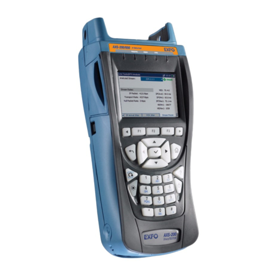
- Page 1 User Guide AXS-200/350 and AXS-200/360 OLTS and Power Meter...
- Page 2 EXFO Electro-Optical Engineering Inc. (EXFO). Information provided by EXFO is believed to be accurate and reliable. However, no responsibility is assumed by EXFO for its use nor for any infringements of patents or other rights of third parties that may result from its use.
-
Page 3: Table Of Contents
Contents Contents Certification Information ......................v 1 Introducing Your AXS-200/350 OLTS and AXS-200/360 Power Meter ..1 Main Features .........................1 Models ............................1 LEDs Description ........................2 Module Ports Description .......................3 Conventions ..........................4 2 Safety Information ..................5 Laser Safety Information (Units without VFL) ................5 Laser Safety Information (Units with VFL) ................6... - Page 4 Recalibrating the Unit ......................43 Recycling and Disposal (Applies to European Union Only) ............44 8 Troubleshooting ..................45 Solving Common Problems ....................45 Finding Information on the EXFO Web Site ................46 Contacting the Technical Support Group ................46 Transportation ........................47 9 Warranty ......................49 General Information ......................49 Liability ..........................50...
-
Page 5: Certification Information
F.C.C. Information Electronic test equipment is exempt from Part 15 compliance (FCC) in the United States. However, compliance verification tests are systematically performed on most EXFO equipment. Information Electronic test equipment is subject to the EMC Directive in the European Union. - Page 6 DECLARATION OF CONFORMITY Application of Council Directive(s): 73/23/EEC - The Low Voltage Directive 89/336/EEC - The EMC Directive And their amendments Manufacturer’s Name: EXFO Electro-Optical Engineering Inc. Manufacturer’s Address: 400 Godin Avenue Quebec, Quebec Canada, G1M 2K2 (418) 683-0211 Equipment Type/Environment: Test &...
- Page 7 DECLARATION OF CONFORMITY Application of Council Directive(s): 73/23/EEC - The Low Voltage Directive 89/336/EEC - The EMC Directive And their amendments Manufacturer’s Name: EXFO Electro-Optical Engineering Inc. Manufacturer’s Address: 400 Godin Avenue Quebec, Quebec Canada, G1M 2K2 (418) 683-0211 Equipment Type/Environment: Test &...
-
Page 9: Introducing Your Axs-200/350 Olts And Axs-200/360 Power Meter
Introducing Your AXS-200/350 OLTS and AXS-200/360 Power Meter The AXS-200/350 OLTS and AXS-200/360 Power Meter features a pass/fail LED indicator and lets you set your own thresholds for loss measurements. It facilitates data management and enables data transfer via Bluetooth or USB connection. -
Page 10: Leds Description
Introducing Your AXS-200/350 OLTS and AXS-200/360 Power Meter LEDs Description LEDs Description The figure below describes each LED on your unit. The source is on Green: pass when the LED is red (AXS-350 only). Red: fail VFL is on when the LED is red. -
Page 11: Module Ports Description
Introducing Your AXS-200/350 OLTS and AXS-200/360 Power Meter Module Ports Description Module Ports Description The AXS-200/350 and AXS-200/360 comes equipped with different ports depending on the options you have chosen. Source port One singlemode port One multimode port One singlemode port and one multimode port... -
Page 12: Conventions
Introducing Your AXS-200/350 OLTS and AXS-200/360 Power Meter Conventions Conventions Before using the product described in this manual, you should understand the following conventions: ARNING Indicates a potentially hazardous situation which, if not avoided, could result in death or serious injury. Do not proceed unless you understand and meet the required conditions. -
Page 13: Safety Information
Safety Information ARNING Do not install or terminate fibers while a light source is active. Never look directly into a live fiber and ensure that your eyes are protected at all times. ARNING Use of controls, adjustments and procedures for operation and maintenance other than those specified herein may result in hazardous radiation exposure. -
Page 14: Laser Safety Information (Units With Vfl)
The following label(s) indicate that the product contains a Class 3R source: If VFL option is available IEC 60825-1:1993+A2:2001 21 CFR 1040.10 LASER RADIATION AVOID DIRECT EYE EXPOSURE CLASS 3R LASER PRODUCT λ: 650 ±10 nm P out maximum < 5mW (into free space) AXS-200/350 and AXS-200/360... -
Page 15: Using The Loss Certification Wizard
Using the Loss Certification Wizard The Loss Certification Wizard allows you to enter all the information required to take measurements. It helps you to go through the different steps in order. Note: You can exit the wizard at anytime by pressing Exit Certification. To use the Loss Certification Wizard: 1. - Page 16 16. Repeat steps 14 and 15 to set a reference for other wavelengths. 17. Press Next. 18. Enter the cable name and then the fiber identification parameters (for more information see Setting Autonaming Scheme on page 28). 19. Press Next. AXS-200/350 and AXS-200/360...
- Page 17 Using the Loss Certification Wizard 20. Select the measurement unit to used for the cable length. Note: According to the length measurement method you have selected at step 7 you either enter the length of the cable or the beginning and the end markings of the cable sheath.
-
Page 19: Measuring Power Or Loss
Measuring Power or Loss Nulling the Offsets Temperature and humidity variations affect the performance of electronic circuits and optical detectors. Nulling the offsets eliminates these effects. Your unit has been designed not to require offset nulling under normal operation, but you should perform it whenever environmental conditions change significantly or when measuring very low power values. -
Page 20: Defining A List Of Favorite Wavelengths
3. If you are satisfied with the list, press If you want to add a wavelength, close the list, select New Wavelength, and enter a value. The new value appears in the Item list followed by PM=Yes. AXS-200/350 and AXS-200/360... - Page 21 Measuring Power or Loss Defining a List of Favorite Wavelengths To hide a wavelength in the power meter list: 1. Press , select Power Meter, and then Configuration. 2. From the Power Meter tab, select Item, and then press 3. Select the wavelength to hide, and press 4.
-
Page 22: Setting Power Correction Factor
Note: When a correction factor has been set for a wavelength, the value is displayed next to the wavelength in the Item list. 4. Select Correction factor and press 5. Enter the correction factor value and press again. AXS-200/350 and AXS-200/360... -
Page 23: Deactivating The Offset Nulling Message
Measuring Power or Loss Deactivating the Offset Nulling Message Deactivating the Offset Nulling Message By default, when the unit detects a significant change in temperature or humidity, it displays a message requesting you to perform an offset nulling. If you do not want the unit to show this message, proceed as follows: To deactivate the offset nulling message: 1. -
Page 24: Setting Pass/Fail Thresholds
, select Power Meter, and then Configuration. 2. Select the Thresholds tab. 3. Using the up/down arrows, select Threshold type, and press 4. Select Basic power meter and press 5. Enter the threshold parameters for each wavelength. AXS-200/350 and AXS-200/360... - Page 25 Measuring Power or Loss Setting Pass/Fail Thresholds To revert to factory settings: Press Revert to Factory Settings. To set the pass/fail thresholds for Network standard: 1. Press , select Power Meter, and then Configuration. 2. Select the Thresholds tab. 3. Using the up/down arrows, select Threshold type, and press 4.
- Page 26 User defined values to set your own threshold. If you have chosen User defined values, you should name your threshold configuration in the Filename box, and press Save. 6. Enter the threshold parameters for each wavelength. AXS-200/350 and AXS-200/360...
-
Page 27: Defining The Cable Information
Measuring Power or Loss Defining the Cable Information Defining the Cable Information The cable information allows you to enter the following information: Singlemode or multimode fiber Number of connector pairs, splices, harnesses, and modules Measurement method for length offers you two choices: Manual entry: when you know the cable length Sheath marking: when you want to use the provided marks on the cable sheath... -
Page 28: Defining The Job Information
Note: Changes to job information do not apply to data already saved. Report Viewer only displays job information as entered at the time the cable was created. If you want to use different information for other fibers in a cable, create a new cable file. AXS-200/350 and AXS-200/360... -
Page 29: Referencing Your Power Meter To A Source
Measuring Power or Loss Referencing Your Power Meter to a Source Referencing Your Power Meter to a Source When working with a reference power value, your power meter displays the loss of the fiber under test only, because the reference power is subtracted from the measured power. - Page 30 Power source meter 2. Activate the source at the desired wavelength. 3. Press , select Power Meter, and then Instrument View. 4. Using the up/down arrows, select Wavelength, and press 5. Select the matching wavelength, and press AXS-200/350 and AXS-200/360...
- Page 31 Measuring Power or Loss Referencing Your Power Meter to a Source 6. Using the corresponding function key (F1/F2/F3), press Set Reference. The power meter stores the currently detected power as the new reference power. The new reference power is displayed in the bottom left corner (dBm) and current loss reading is automatically switched to dB.
-
Page 32: Measuring Power Or Loss
Loss Certification Wizard to configure the unit. Note: If you have referenced your power meter to a source, connect the fiber under test to the reference jumpers used for referencing. Reference Reference jumper jumper Light Power source meter AXS-200/350 and AXS-200/360... - Page 33 Measuring Power or Loss Measuring Power or Loss 5. Activate the source at the desired wavelength. 6. If no referencing was done, match the source and power meter wavelengths. If the source emits is equipped with a feature such as Auto-wavelength or Auto-switching, the power meter automatically matches the source wavelength.
-
Page 34: Detecting Wavelength Automatically
To receive the source's wavelength value automatically: 1. Connect the source to your power meter. 2. Turn on the source. 3. Activate the Auto-wavelength or Auto-switching mode. Activate the equivalent feature. Your power meter automatically matches the source wavelength. AXS-200/350 and AXS-200/360... -
Page 35: Activating Hold Min./Max. Power Mode
Measuring Power or Loss Activating Hold Min./Max. Power Mode Activating Hold Min./Max. Power Mode With the Hold Min./Max. mode you can record extreme values of a varying power signal. You could use it to test the stability of a light source over time. In this mode, the unit displays the minimum or maximum power value read up to now. -
Page 36: Setting Autonaming Scheme
2. Using the arrows next to the function keys (F1/F2/F3), display Cable and, using the corresponding function key, press Cable. 3. Using the up/down arrows, select New Cable, and then press 4. Enter the required information and press Apply to confirm the changes. AXS-200/350 and AXS-200/360... -
Page 37: Managing Data
Measuring Power or Loss Managing Data Managing Data You can save power/loss values in your unit. You will save and recall this data according to the cable name and fiber ID. MPORTANT You cannot recover deleted data. Ensure that you transfer your data to a computer if you intend to use it later. - Page 38 (F1/F2/F3), press Recall. To delete a cable name: 1. Press , select Power Meter, and then Cable Storage. 2. Press to be able to select a cable. 3. Select the cable to delete and press Delete. AXS-200/350 and AXS-200/360...
-
Page 39: Using A Source
Using a Source Your unit can contain two source ports: a 2- or 3- wavelength singlemode port and a 2-wavelength multimode port, depending on the configuration (see Technical Specifications on page 53). The source signal can be continuous (CW or high power) or modulated (270 Hz, 1 kHz, or 2 kHz). -
Page 40: Changing The Source Modulation Mode
To change the signal modulation: 1. Press and select Light Source. 2. Using the arrows next to the function keys (F1/F2/F3), select the View tab. 3. Using the up/down arrows, select Mode and press 4. Select the required mode and press AXS-200/350 and AXS-200/360... -
Page 41: Using The Auto-Switching Mode
Using a Source Using the Auto-Switching Mode Using the Auto-Switching Mode In auto-switching mode, your source automatically switches from one wavelength to another. When connected to the light source, a compatible power meter displays the power value for each wavelength one at a time. The wavelength value appearing on the display changes every two seconds. -
Page 42: Setting The Light Source
5. Connect a reference jumper between the selected output port and the power meter port, and then press Start. The reference will then be displayed in Reference power (dBm). 6. If you want the wavelength to be available in the auto-switching list, select Yes in the list. AXS-200/350 and AXS-200/360... -
Page 43: Sending Source Power Value With Signal
Using a Source Sending Source Power Value with Signal Sending Source Power Value with Signal Your source can transmit a user-defined power value to compatible power meters (such as FOT-600 and FPM-600) through the fiber. If the reference source is far from the power meter, you can connect your source to the power meter to send the reference value. - Page 44 1. Press and select Light Source. 2. Activate the light source at the desired wavelength. 3. Press Send Reference Power. Note: You can send the source power value only if you are in Auto-wavelength or Auto-switching modes. AXS-200/350 and AXS-200/360...
-
Page 45: Using A Vfl
Using a VFL The visual fault locator (VFL) helps you identify bends, faulty connectors, splices, and other causes of signal loss. From its dedicated port, the VFL emits a visible red signal at the location of a fault on the fiber. This signal can be continuous (CW, the default) or blinking (1 Hz). -
Page 47: Maintenance
Use of controls, adjustments, and procedures for operation and maintenance other than those specified herein may result in hazardous radiation exposure. Installing the EXFO Universal Interface (EUI) The EUI fixed baseplate is available for connectors with angled (APC) or non-angled (UPC) polishing. A green border around the baseplate indicates that it is for APC-type connectors. -
Page 48: Cleaning Eui Connectors
1. Remove the EUI from the instrument to expose the connector baseplate and ferrule. Turn Pull Push 2. Moisten a 2.5 mm cleaning tip with one drop of isopropyl alcohol (alcohol may leave traces if used abundantly). AXS-200/350 and AXS-200/360... - Page 49 6c. With a dry lint-free wiping cloth, gently wipe the same surfaces to ensure that the connector and ferrule are perfectly dry. 6d. Verify connector surface with a portable fiber-optic microscope (for example, EXFO’s FOMS) or fiber inspection probe (for example, EXFO’s FIP). OLTS and Power Meter...
-
Page 50: Cleaning Detector Ports
4. While applying light pressure (to avoid breaking the detector window), gently rotate the cleaning tip on the detector window. 5. Repeat step 4 with a dry cleaning tip or blow dry with compressed air. 6. Discard the cleaning tips after one use. AXS-200/350 and AXS-200/360... -
Page 51: Recalibrating The Unit
Under normal use, EXFO recommends calibrating your unit every year. The last calibration dates of your power meter and source are indicated in your unit software. -
Page 52: Recycling And Disposal (Applies To European Union Only)
This equipment was sold after August 13, 2005 (as identified by the black rectangle). Unless otherwise noted in a separate agreement between EXFO and a customer, distributor or commercial partner, EXFO will cover costs related to the collection, treatment, recovery and disposal of... -
Page 53: Troubleshooting
Troubleshooting Solving Common Problems This table presents common problems and their solutions. Problem Cause Solution Restarting the unit after The configuration file is Delete the configuration file encountering a failure has corrupted. (refer to Deleting the not solved the problem. Configuration File). -
Page 54: Finding Information On The Exfo Web Site
Finding Information on the EXFO Web Site Finding Information on the EXFO Web Site The EXFO Web site provides answers to frequently asked questions (FAQs) regarding the use of your AXS-200/350 OLTS and AXS-200/360 Power Meter. To access FAQs: 1. Type http://www.exfo.com... -
Page 55: Transportation
Troubleshooting Transportation **************** Ver. January 2020 542392-3D Mfg. date 465 Godin Avenue Vanier (Quebec) G1M 3G7 CANADA Made in Canada QST442B AXS-35X-XX-XX-XX-XX Model Connector adapter Connector VFL option Transportation Maintain a temperature range within specifications when transporting the unit. Transportation damage can occur from improper handling. The following steps are recommended to minimize the possibility of damage: Pack the unit in its original packing material when shipping. -
Page 57: Warranty
EXFO Electro-Optical Engineering Inc. (EXFO) warrants this equipment against defects in material and workmanship for a period of one year from the date of original shipment. EXFO also warrants that this equipment will meet applicable specifications under normal use. During the warranty period, EXFO will, at its discretion, repair, replace,... -
Page 58: Liability
Liability Liability EXFO shall not be liable for damages resulting from the use of the product, nor shall be responsible for any failure in the performance of other items to which the product is connected or the operation of any system of which the product may be a part. -
Page 59: Service And Repairs
5. Return the equipment, prepaid, to the address given to you by support personnel. Be sure to write the RMA number on the shipping slip. EXFO will refuse and return any package that does not bear an RMA number. -
Page 60: Exfo Service Centers Worldwide
Warranty EXFO Service Centers Worldwide EXFO Service Centers Worldwide If your product requires servicing, contact your nearest authorized service center. EXFO Headquarters Service Center 400 Godin Avenue 1 866 683-0155 (USA and Canada) Quebec (Quebec) G1M 2K2 Tel.: 1 418 683-5498... -
Page 61: A Technical Specifications
MPORTANT The following technical specifications can change without notice. The information presented in this section is provided as a reference only. To obtain this product’s most recent technical specifications, visit the EXFO Web site at www.exfo.com. AXS-200/350 AXS-200/350 SPECIFICATIONS PRELIMINARY... -
Page 62: Axs-200/360
CLASS 3R LASER PRODUCT FOR VFL If VFL option is available Output power (dBm) IEC 60825-1:1993+A2:2001 21 CFR 1040.10 LASER RADIATION AVOID DIRECT EYE EXPOSURE CLASS 3R LASER PRODUCT λ: 650 ±10 nm P out maximum < 5mW (into free space) AXS-200/350 and AXS-200/360... -
Page 63: Index
CF. see correction factor dust cap ..........40 cleaning EUI connectors, cleaning ......40 detector ports........42 EXFO service centers ........52 EUI connectors........40 EXFO universal interface. see EUI front panel..........39 EXFO Web site ..........46 UI connectors ........40 configuration file, deleting...... - Page 64 UI connectors ........40 power or loss measurement....24 measuring threshold configuration ......16 loss ............24 product power ............ 24 identification label ......... 46 message about offset nulling ...... 15 specifications ........46, 53 protective cap..........42 AXS-200/350 and AXS-200/360...
- Page 65 LED......2 service and repairs........51 auto-switching mode, light source ..33 service centers ..........52 correction factor ........14 shipping to EXFO ........51 list of favorites ........12 signal modulation ........32 table ............12 source. see light source threshold configuration ......
- Page 66 EXFO ASIA-PACIFIC 151 Chin Swee Road SINGAPORE 169876 #03-29, Manhattan House Tel.: +65 6333 8241 · Fax: +65 6333 8242 TOLL-FREE (USA and Canada) 1 800 663-3936 © 2008 EXFO Electro-Optical Engineering Inc. All rights reserved. Printed in Canada (2008-04)
Need help?
Do you have a question about the AXS-200 and is the answer not in the manual?
Questions and answers