Table of Contents
Advertisement
Quick Links
This information applies only to the
PM-1100 Optical Power Meter user guide.
GPIB Commands and Queries
The FORM:READ:DATA? query does not exist.
The MMEM:ACQ:DATA:RECA:VALUE? query should be defined as
follows:
MMEMory:ACQuisition:DATA:RECAll:VALUE?
Description This query returns the measurement saved in the <data>
Syntax
Parameters The <data> parameter represents the memory location where
Response
Notes
Example
P/N: 1051923
A
DDENDUM
memory location.
MMEM:ACQ:DATA:RECA:VALUE?<space><data>
measurement data is stored (out of the 1024 available).
Measurement data saved in the specified memory location in
the "±999.999E±99" format.
Use the MMEM:ACQ:DATA:RECA:UNIT? query to get the
corresponding measurement units.
Use the MMEM:ACQ:DATA:RECA:WAVE? query to get the
wavelength at which the measurement was taken.
MMEM:ACQ:DATA:RECA:VALUE? 1021
January 2008
1/4
Advertisement
Table of Contents

Related Manuals for EXFO PM-1100


Summary of Contents for EXFO PM-1100
- Page 1 DDENDUM This information applies only to the PM-1100 Optical Power Meter user guide. GPIB Commands and Queries The FORM:READ:DATA? query does not exist. The MMEM:ACQ:DATA:RECA:VALUE? query should be defined as follows: MMEMory:ACQuisition:DATA:RECAll:VALUE? Description This query returns the measurement saved in the <data>...
- Page 2 The MMEM:ACQ:DATA:RECA:WAV? query should be named and defined as follows: MMEMory:ACQuisition:DATA:RECAll:WAVElength? Description This query returns the wavelength corresponding to the last value fetched with the MMEM:ACQ:DATA:RECA:VALUE? query. Syntax MMEM:ACQ:DATA:RECA:WAVE? Response A wavelength in the “9999 nm” format. Notes Use the MMEM:ACQ:DATA:RECA:UNIT? query to get the corresponding measurement units.
- Page 3 The SENS:FREQ:CAT? query should be named and defined as follows: SENSitivity:FREQuency:CATAlog? Description This query returns a list of available sampling rates. Syntax SENS:FREQ:CATA? Response List of available sampling rates in the “40.0;20.0;10.0;5.0;1.0;0.5;0.1” format. Example SENS:FREQ:CATA? The SENS:POW:WAV command should be named and defined as follows: SENSitivity:POWer:WAVElength Description This command selects a new operating wavelength.
- Page 4 The UNIT:POW command should be named and defined as follows: UNIT:POWer Description This command changes the measurement display units. Syntax UNIT:POW<space><units> Parameters The <units> parameter can be W: measured value displayed in watts (pw, nw, μw, or mw) DBM: measured value displayed in dBm DB: measured value displayed in dB relative to the current reference DW: measured value displayed in watts relative to the...
- Page 5 OPTICAL POWER METER PM-1100 R&D AND MANUFACTURING USER GUIDE...
- Page 6 Engineering Inc. (EXFO). Information provided by EXFO is believed to be accurate and reliable. However, no responsibility is assumed by EXFO for its use nor for any infringements of patents or other rights of third parties that may result from its use.
-
Page 7: Table Of Contents
Contents Contents Certification Information ......................v 1 Introducing the PM-1100 Optical Power Meter .......... 1 Front Panel ..........................2 Back Panel ..........................3 RS-232 Connector Pinout ......................4 Conventions ..........................5 2 Safety Information ..................7 Laser Safety Information ......................7 Electrical Safety Information ....................8 3 Getting Started with Your Optical Power Meter ........ - Page 8 Recalibrating the Unit ......................52 Upgrading the Embedded Software ..................52 Recycling and Disposal (Applies to European Union Only) ............55 7 Troubleshooting ..................57 Finding Information on the EXFO Web Site ................57 Contacting the Technical Support Group ................58 Transportation ........................59 8 Warranty ......................61 General Information ......................61...
-
Page 9: Certification Information
F.C.C. Information Electronic test equipment is exempt from Part 15 compliance (FCC) in the United States. However, compliance verification tests are systematically performed on most EXFO equipment. Information Electronic test equipment is subject to the EMC Directive in the European Union. - Page 10 400 Godin Avenue Quebec, Quebec Canada G1M 2K2 Equipment Type/Environment: Industrial Scientific Equipment Trade Name/Model No.: PM-1100 Optical Power Meter Standard(s) to which Conformity is Declared: EN 55011:1993 Limits and Methods of Measurement of Radio Disturbance Characteristics of Information Technology Equipment.
-
Page 11: Introducing The Pm-1100 Optical Power Meter
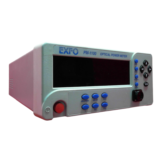
Introducing the PM-1100 Optical Power Meter The PM-1100 Optical Power Meter provides accurate power measurements over a wide dynamic range with high resolution and excellent linearity. It is particularly suitable for automated measurements. The built-in memory lets you store up to 20 preselected wavelengths of the sources under test. -
Page 12: Front Panel
Introducing the PM-1100 Optical Power Meter Front Panel Front Panel Recall menu access Arrow buttons for Store menu access Display menu navigation and parameter setting Measurement units control On/off button Wavelength control Detector port Relative mode access Setup menu access... -
Page 13: Back Panel
Part number Version number PM-1101 A-1.0 Ver. Dynamic range +10 to -100 dBm 450 to 1100 nm Spectral range Mfg. October 97 12345-B date Manufacturing Serial number date Note: Your PM-1100 may slightly differ from the illustration. Optical Power Meter... -
Page 14: Rs-232 Connector Pinout
Introducing the PM-1100 Optical Power Meter RS-232 Connector Pinout RS-232 Connector Pinout The RS-232 connector (serial port) at the back of the PM-1100 uses a DTE pinout configuration. 1 2 3 4 6 7 8 9 Description Direction Receive (Rx) -
Page 15: Conventions
Introducing the PM-1100 Optical Power Meter Conventions Conventions Before using the product described in this manual, you should understand the following conventions: ARNING Indicates a potentially hazardous situation which, if not avoided, could result in death or serious injury. Do not proceed unless you understand and meet the required conditions. -
Page 17: Safety Information
Safety Information Laser Safety Information ARNING Do not install or terminate fibers while a light source is active. Never look directly into a live fiber and ensure that your eyes are protected at all times. ARNING Use of controls, adjustments and procedures for operation and maintenance other than those specified herein may result in hazardous radiation exposure. -
Page 18: Electrical Safety Information
The color coding used in the electric cable depends on the cable. New plugs should meet the local safety requirements and include: adequate load-carrying capacity ground connection cable clamp MPORTANT EXFO assumes no liability if you attempt to perform internal service on this unit. PM-1100... - Page 19 Safety Information Electrical Safety Information ARNING Use this unit indoors only. Position the unit so that the air can circulate freely around it. Operation of any electrical instrument around flammable gases or fumes constitutes a major safety hazard. Do not remove unit covers during operation. To avoid electrical shock, do not operate the unit if any part of the outer surface (covers, panels, etc.) is damaged.
- Page 20 Measured in 0 °C to 31 °C (32 °F to 87.8 °F) range, decreasing linearly to 50 % at 40 °C (104 °F). ± Not exceeding 10 % of the nominal voltage. The following label is located on the back panel of the unit: PM-1100...
-
Page 21: Getting Started With Your Optical Power Meter
Getting Started with Your Optical Power Meter Turning On and Off the Optical Power Meter Before turning the Optical Power Meter on, please read Electrical Safety Information on page 8. To turn the unit on and off, use the red button in the lower left corner of the front panel. -
Page 22: Selecting A Menu Or A Menu Option
RECALL SAVE GPIB-RS To move (in loop) between the menu items, use the left/right arrows. To exit a menu: press the button that gave access to the menu, or scroll (left/right arrows) until EXIT is displayed, then press ENTER. PM-1100... -
Page 23: Operating The Optical Power Meter
To ensure maximum power and to avoid erroneous readings: Always clean fiber ends as explained below before inserting them into the port. EXFO is not responsible for damage or errors caused by bad fiber cleaning or handling. Ensure that your patchcord has appropriate connectors. Joining mismatched connectors will damage the ferrules. -
Page 24: Nulling Electrical Offsets
EXFO recommends performing a nulling before every test session. Since temperature and humidity variations affect the performance of electronic circuits and optical detectors, EXFO also recommends performing a nulling of the electrical offsets whenever environmental conditions change. -
Page 25: Measuring Absolute Power
Operating the Optical Power Meter Measuring Absolute Power Measuring Absolute Power Press dBm/Watt to display the absolute power of the signal received at the detector port. dBm/Watt is also used to toggle between dBm and watts measurement units. When using watts measurement units, the Optical Power Meter will automatically use pW, nW, μW, or mW, according to the λ... -
Page 26: Relative Power
(to edit the shortlist of wavelengths see Customizing the Shortlist of Wavelengths on page 33). Unit of measurement Relative power for the relative power Reference value Unit of measurement for the reference value PM-1100... - Page 27 Relative Power Unit of measurement A delta symbol indicates Relative power for the relative power that the PM-1100 is in relative mode and measuring in watts. Unit of measurement Reference value for reference value When you access relative mode, the Optical Power Meterdisplays the last reference value entered at the current wavelength.
- Page 28 7. Press ENTER. Note: Any value outside the Optical Power Meter measurement range will be rejected. The unit will beep and you will be prompted to enter a new value. 8. To exit the Setup menu, press Setup. PM-1100...
-
Page 29: Average Mode
Operating the Optical Power Meter Average Mode Average Mode Choose Avg in order for the displayed power measurement to be averaged or not. When the average mode is enabled, the eight most recent measurement samples are used to compute an unweighted average. This average is displayed as the measured value. -
Page 30: Recalling Manually Stored Data
To recall the manually stored data: 1. Press Recall. You will see the following display with a register number flashing. 2. Using the up/down arrows, scroll to the register number you want to view. PM-1100... - Page 31 Operating the Optical Power Meter Recalling Manually Stored Data 3. Press ENTER. The selected register will be displayed. A small “M” indicates you Measurement are in Memory Recall mode Measurement unit A delta symbol indicates Wavelength at which the a relative value in watts measurement was taken Note: A dashed line with no unit of measurement indicates an empty register.
-
Page 32: Erasing Manually Stored Data
2. Scroll (left/right arrows) to CLR DATA. MPORTANT After you press ENTER, all the manually stored data in the 512 registers will be deleted without any other warning. 3. Press ENTER. 4. To exit the Recall menu, press Recall. PM-1100... -
Page 33: Programming An Acquisition
Operating the Optical Power Meter Programming an Acquisition Programming an Acquisition You can program the PM-1100 to automatically acquire absolute or referenced measurements. The following program parameters may be set: delay: the beginning of the program may be delayed by up to 999 hours, 59 minutes, and 59 seconds;... - Page 34 2a. Press ENTER. The first digit will start flashing. Use the up/down arrows to change the flashing digit and the left/right arrows to activate the next digit. 2b. Once the delay is set, press ENTER. 3. Press the right arrow. You will get the following display. Hours Minutes Seconds PM-1100...
- Page 35 6a. Press ENTER. The digit will start flashing. Use the up/down arrows to toggle between the possible number of acquisitions (the number of acquisitions the PM-1100 can store depends on the duration you set at step 4). 6b. Once the number of samples is set, press ENTER.
-
Page 36: Starting The Acquisition
If you want to know how much time is left in the delay (before the acquisition starts), press Program, and then scroll (left/right arrows) to DELAY. If you want to know how much time is left in the acquisition, press Program, then scroll (left/right arrows) to DURATION. PM-1100... -
Page 37: Stopping The Acquisition
Operating the Optical Power Meter Stopping the Acquisition Stopping the Acquisition Once the acquisition starts, it continues until the set duration has expired. When the acquisition is over, the unit beeps, PRG STOP is displayed, and the data is stored automatically. You can also terminate the acquisition before the set duration has elapsed. -
Page 38: Recalling Acquisition Data
The data stored during a programmed acquisition (see Programming an Acquisition on page 23) can be recalled one sample at a time. Each sample is stored in a memory register. To recall acquisition data: 1. Press Recall. 2. Scroll (let/right arrows) to ACQ. A register number will flash. PM-1100... - Page 39 Operating the Optical Power Meter Recalling Acquisition Data 3. Using the up/down arrows, scroll to the register number you want to view. 4. Press ENTER. The selected register will be displayed. A small “M” indicates you Measurement are in Memory Recall mode Measurement unit A delta symbol indicates Wavelength at which the...
-
Page 40: Erasing Acquisition Data
Customizing Your Optical Power Meter Customized settings are kept in non-volatile memory and are, therefore, saved when the PM-1100 is turned off. Settings for a specific use or user may also be saved (up to 10 configurations can be saved). See Saving a Configuration on page 39. - Page 41 Operating the Optical Power Meter Customizing Your Optical Power Meter To change the resolution: 1. Press Setup. You will see the following screen: Current resolution setting 2. Press ENTER. The current resolution setting starts flashing. 3. Scroll (up/down arrows) to select a new resolution setting (0, 1, 2, 3, or Auto).
- Page 42 Customizing Your Optical Power Meter Changing the Sampling Rate You can set the number of samples taken by the PM-1100 every second: 0.1 (1 every 10 seconds), 0.5 (1 every 2 seconds), 1, 5, 10, 20, or 40. Note: The maximum display refresh rate of the PM-1100 is 5 values every second, no matter what sampling rate is selected.
- Page 43 Operating the Optical Power Meter Customizing Your Optical Power Meter Customizing the Shortlist of Wavelengths The Optical Power Meter detector port can measure optical power at many wavelengths. The accepted wavelengths (spectral range, see Technical Specifications on page 65) depend on the type of detector with which the Optical Power Meter is equipped.
- Page 44 3. Scroll (up/down arrows) until DEL ALL appears in the lower portion of the display. 4. Press ENTER. 5. To exit the Setup menu, press Setup. Note: The wavelength that is currently active in absolute mode cannot be erased. PM-1100...
- Page 45 Operating the Optical Power Meter Customizing Your Optical Power Meter Setting an Offset An offset can be applied to any measurement that is displayed in either dB or dBm. The offset value, which can be positive or negative, is always expressed in dB and is added to the measured power.
- Page 46 3. Press ENTER. The first digit will start flashing. 4. Set a new date (use the up/down arrows to change the flashing digit and the left/right arrows to activate the next digit). 5. Press ENTER. 6. To exit the Setup menu, press Setup. PM-1100...
- Page 47 Operating the Optical Power Meter Customizing Your Optical Power Meter Setting the Clock The time must be entered according to the 24-hour format. To set the clock: 1. Press Setup. 2. Scroll (left/right arrows) to TIME. Hour Minutes Seconds 3. Press ENTER. The first digit will start flashing. 4.
- Page 48 4. Use the up/down arrows to modify the dimmer: LO, HI, or OFF. 5. Press ENTER. Note: Setting the dimmer to OFF turns off the display. Press any key to turn the display back on. 6. To exit the Setup menu, press Setup. PM-1100...
- Page 49 Operating the Optical Power Meter Customizing Your Optical Power Meter Saving a Configuration Once the PM-1100 is customized for a specific application or user, it is possible to save the configuration. Saved parameters are: resolution sampling rate current wavelength and corresponding reference offset Up to ten configurations can be saved and recalled as needed.
- Page 50 3. Press ENTER. The configuration number (bottom of the screen) will start flashing. 4. Use the up/down arrows to select the number of the configuration you want to recall. 5. Press ENTER. 6. To exit the Setup menu, press Setup. PM-1100...
-
Page 51: Controlling Your Optical Power Meter Remotely
Remote appears in the lower left corner of the display. Note: If you have already designed a GPIB program to control a power meter from EXFO’s IQ Series (IQ-1100, IQ-1200, or IQ-1500), you can reuse sections for the PM-1100 Optical Power Meter. -
Page 52: Setting The Optical Power Meter For Remote Control
4. Using the up/down arrows, enter a new setting. a numbered setting represents a GPIB address (between 1 and 30) for RS-232 control, scroll (up/down arrows) to RS-232 (before setting 1 or after setting 30). 5. Press ENTER. 6. To exit the Setup menu, press Setup. PM-1100... -
Page 53: Communication Parameters
Controlling Your Optical Power Meter Remotely Communication Parameters Communication Parameters For GPIB Communication Terminate Read on EOS Set EOI with EOS on Writes Type of compare on EOS 8-bits EOS byte Sens EOI at end of Writes GPIB Primary address See Setting the Optical Power Meter for Remote Control on page 42 GPIB Secondary address... -
Page 54: Standard Status Data Structure
Execution Error Message Available Event Status Summary Bit Command Error Command Error Event Status Message Available Summary Bit User Request User Request Master Summary Request Service / Status Master Summary Status Power On Power On Operation Status Operation Status PM-1100... - Page 55 Controlling Your Optical Power Meter Remotely Standard Status Data Structure Standard Event Status Register (ESR) & & & & & & & & Standard Event Status Enable Register (ESE) Output Queue not Empty read by serial poll ESB MAV Status Byte Service Request Register Generation...
-
Page 56: Command Structure
<space> indicates that a space is required; and <digits> is the command parameter. For example, the typical FORM:READ:DATA 1 command instructs the PM-1100 to display a power measurement with 1 digit after the decimal point. Note: It is recommended to retrieve the response immediately after each query. -
Page 57: Error Messages
Controlling Your Optical Power Meter Remotely Error Messages Error Messages The Optical Power Meter can manage both system and device-specific errors. The generic format for error messages is illustrated below. <Device dependent <Error number> “ <Error description> “ information> As shown in the above figure, the message contains three parts: the error number, error description, and device dependent information. -
Page 59: Maintenance
Maintenance To help ensure long, trouble-free operation: Keep the unit free of dust. Store unit at room temperature in a clean and dry area. Keep the unit out of direct sunlight. Avoid high humidity or significant temperature fluctuations. Avoid unnecessary shocks and vibrations. If any liquids are spilled on or into the unit, turn off the power immediately and let the unit dry completely. -
Page 60: Cleaning Detector Ports
4. While applying light pressure (to avoid breaking the detector window), gently rotate the cleaning tip on the detector window. 5. Repeat step 4 with a dry cleaning tip or blow dry with compressed air. 6. Discard the cleaning tips after one use. PM-1100... -
Page 61: Replacing Fuses
Replacing Fuses Replacing Fuses The PM-1100 Optical Power Meter contains two F2.0L250V-type fuses (IEC, 5 mm x 20 mm (0.197 in x 0.787 in), fast-acting, low breaking capacity, 250 V). The fuse holder is located at the back of the Optical Power Meter, just beside the power inlet. -
Page 62: Recalibrating The Unit
Under normal use, EXFO recommends calibrating your unit every year. Upgrading the Embedded Software To upgrade the Optical Power Meter embedded software, you will need to obtain the upgrade files from EXFO’s Technical Support Group. You will also need a null-modem cable. MPORTANT You may upgrade software in DOS, Windows 3.1, Windows 9x, or... - Page 63 Maintenance Upgrading the Embedded Software 5. If the software upgrade is performed in Windows 98, you must restart your computer in DOS mode before launching the upgrade program. In other cases, simply exit to DOS. 6. Go to the “C:\Test” folder and launch the upgrade program by typing the following line (spaces are required between parameters): Lo0006.exe /C:2 /F:c:\test\filename.hex /S:19200 Parameters can be decoded as follows:...
- Page 64 Click on Close to hide the dialog box. 9. Turn the Optical Power Meter off, and then on again. Some units will display the new version number at start-up, otherwise press the up and right arrow keys together while the unit is turned on. PM-1100...
-
Page 65: Recycling And Disposal (Applies To European Union Only)
This equipment was sold after August 13, 2005 (as identified by the black rectangle). Unless otherwise noted in a separate agreement between EXFO and a customer, distributor or commercial partner, EXFO will cover costs related to the collection, treatment, recovery and disposal of... -
Page 67: Troubleshooting
Troubleshooting Finding Information on the EXFO Web Site The EXFO Web site provides answers to frequently asked questions (FAQs) regarding the use of your PM-1100 Optical Power Meter. To access FAQs: 1. Type http://www.exfo.com in your Internet browser. 2. Click on the Support tab. -
Page 68: Contacting The Technical Support Group
Contacting the Technical Support Group To obtain after-sales service or technical support for this product, contact EXFO at one of the following numbers. The Technical Support Group is available to take your calls from Monday to Friday, 7:30 a.m. to 8:00 p.m. -
Page 69: Transportation
Troubleshooting Transportation Transportation Maintain a temperature range within specifications when transporting the unit. Transportation damage can occur from improper handling. The following steps are recommended to minimize the possibility of damage: Pack the unit in its original packing material when shipping. Avoid high humidity or large temperature fluctuations. -
Page 71: Warranty
EXFO Electro-Optical Engineering Inc. (EXFO) warrants this equipment against defects in material and workmanship for a period oftwo years from the date of original shipment. EXFO also warrants that this equipment will meet applicable specifications under normal use. During the warranty period, EXFO will, at its discretion, repair, replace,... -
Page 72: Liability
Liability Liability EXFO shall not be liable for damages resulting from the use of the product, nor shall be responsible for any failure in the performance of other items to which the product is connected or the operation of any system of which the product may be a part. -
Page 73: Service And Repairs
5. Return the equipment, prepaid, to the address given to you by support personnel. Be sure to write the RMA number on the shipping slip. EXFO will refuse and return any package that does not bear an RMA number. -
Page 74: Exfo Service Centers Worldwide
Warranty EXFO Service Centers Worldwide EXFO Service Centers Worldwide If your product requires servicing, contact your nearest authorized service center. EXFO Headquarters Service Center 400 Godin Avenue 1 866 683-0155 (USA and Canada) Quebec (Quebec) G1M 2K2 Tel.: 1 418 683-5498... -
Page 75: A Technical Specifications
MPORTANT The following technical specifications can change without notice. The information presented in this section is provided as a reference only. To obtain this product’s most recent technical specifications, visit the EXFO Web site at www.exfo.com. SPECIFICATIONS MODEL PM-1102X PM-1613/1623... -
Page 77: B Remote Control Commands
Remote Control Commands This section presents detailed information about the commands and queries supplied with your PM-1100 Optical Power Meter. IEEE 488.2 Commands—Quick Reference The Optical Power Meter recognizes the main commands identified in IEEE-488.2. The table below summarizes these commands. The commands are fully explained on the following pages. - Page 78 SRQ. Syntax *ESE<space><value> Parameter The <value> parameter must be between 0 and 255. *ESE? Description This query reads the contents of the Standard Event Status Enable Register (ESE). Syntax *ESE? Response A binary integer between 0 and 255. PM-1100...
- Page 79 A binary integer between 0 and 255. *IDN? Description This query reads the IQ system identification string. Syntax *IDN? Response “EXFO E.-O. Eng PM-1100 Vxx.xx”, where xx.xx is the current product version. *LOK Description This command is used to set the Remote Lockout programming state. Syntax...
- Page 80 Remote Control Commands IEEE 488.2 Commands—Quick Reference *OPC Description This command will cause the PM-1100 to generate the “Operation complete” message in the Standard Event Status Register (ESR) when all pending selected PM-1100 operations have been completed. Syntax *OPC Example *OPC;*IDN?
- Page 81 Remote Control Commands IEEE 488.2 Commands—Quick Reference *RST Description This command empties the step response list. It is only seen when it is part of another multiple command. In the example below, by adding this command after *IDN?, you will not be able to access the answer.
- Page 82 Syntax *SRE? Response A binary integer between 0 and 255. *STB? Description This query returns the contents of the Status Byte Register (STB). Syntax *STB? Response A binary integer between 0 and 255. *TRG Description Not supported Syntax *TRG PM-1100...
- Page 83 Remote Control Commands IEEE 488.2 Commands—Quick Reference *TST? Description This query initiates an internal self-test and returns a binary value indicating the results of the test. Syntax *TST? Response A binary value: “0” if the test is complete with no errors “1”...
-
Page 84: Product-Specific Commands-Quick Reference
<0|1|2|3|4> Set display resolution [DATA]? (0|1|2|3|4) Get display resolution INIT CONT <0|1> Start/stop continuous measurements CONT? (0|1) Continuous measure- ments in progress? [IMM] — Store single measurement STOR <0 to 513> Initialize memory location MMEM ACQ <0|1> Start/stop acquisition PM-1100... - Page 85 Remote Control Commands Product-Specific Commands—Quick Reference Parameter/ Command Description Response MMEM ACQ? (0|1) Acquisition in progress? DATA? (0 to 1025) Get number of acquired measure- ment DATA RECA UNIT? (0|1|2|3) Get measurement units VALU? (0 to 1025) Get acquired measurement WAV? (9999 nm) Get wavelength —...
- Page 86 SYST ERR? Error code Next error from error queue? VERS? Current version Identification string? UNIT <WATT|DB|DBM| Set display unit WATT> These commands are not executed if a data acquisition is in progress. The “Program running” message will be returned. PM-1100...
-
Page 87: Product-Specific Commands-Description
Syntax ABOR(0..26) Example ABOR3 DISPlay:DIMMer Description This command is used to adjust the intensity of the PM-1100 display (high or low) or to turn off the display without turning off the unit. Syntax DISP:DIMM<space><data> Parameters The <data> parameter can be “HI”, “LO”, or “OFF”. - Page 88 Remote Control Commands Product-Specific Commands—Description DISPlay:DIMMer? Description This query returns the intensity of the PM-1100 display (high, low, or off) Syntax DISP:DIMM? Response “HI” if the intensity is high “LO” if the intensity is low “OFF” if the display is off...
- Page 89 Remote Control Commands Product-Specific Commands—Description FORMat:READings[:DATA] Description This command changes the resolution of the displayed power value, when dB or dBm is selected. Syntax FORM(0..26):READ[:DATA]<space><digits> Parameters The <digits> parameter can be: “0” -zero digit after the decimal point “1” -one digit after the decimal point “2”...
- Page 90 FETC[:SCAL]:POW:DC? query. Values can be power or loss measurements, depending on the current measurement mode of the PM-1100. Syntax INIT:CONT<space><boolean> Parameters The <boolean> value can be “0”...
- Page 91 Description This command stores a value in the initialized memory location so it can be fetched at any time with the FETC[:SCAL]:POW:DC? query. Values can be power or loss measurements, depending on the current measurement mode of the PM-1100. Syntax INIT[:IMM]...
- Page 92 MMEM:ACQ 1 MMEMory:ACQuisition? Description This query returns a value indicating whether data acquisition is in progress. Syntax MMEM:ACQ? Response The response is in the format “1” data acquisition is in progress “0” data acquisition is not in progress Example MMEM:ACQ? PM-1100...
- Page 93 Remote Control Commands Product-Specific Commands—Description MMEMory:ACQuisition:DATA? Description This command returns the number of data saved by the last acquisition. Syntax MMEM:ACQ:DATA? Response Number of acquired data saved in memory locations in the “600” format. Example MMEM:ACQ:DATA? MMEMory:ACQuisition:DATA:RECAll:UNIT? Description This query returns the measurement units corresponding to the last value fetched with the MMEM:ACQ:DATA:RECA:VALUE? query.
- Page 94 Example MMEM:ACQ:DATA:RECA:VALUE? 1021 MMEMory:ACQuisition:DATA:RECAll:WAV elength Description This query returns the wavelength corresponding to the last value fetched with the MMEM:ACQ:DATA:RECA:VALUE? query. Syntax MMEM:ACQ:DATA:RECA:WAV? Response A wavelength in the “9999 nm” format. Example MMEM:ACQ:DATA:RECA:WAV? PM-1100...
- Page 95 Remote Control Commands Product-Specific Commands—Description MMEMory:ACQuisition:DELete Description This command clears the 1024 memory locations reserved for the acquisition data. Syntax MMEM:ACQ:DEL MMEMory:ACQuisition:DELAy Description This command changes the delay parameter for the acquisition setup. Syntax MMEM:ACQ:DELA<space><delay> Parameters The <delay> parameter is the delay before the acquisition starts in the “HHH,MM,SS”...
- Page 96 S = valid number of samples (MUST be a whole number) Example MMEM:ACQ:SAMP 200 MMEMory:ACQuisition:SAMPles? Description This command returns the current number of samples for the acquisition setup. Syntax MMEM:ACQ:SAMP? Response Current number of samples in the “1” format Example MMEM:ACQ:SAMP? PM-1100...
- Page 97 Remote Control Commands Product-Specific Commands—Description READ[:SCALar]:POWer:DC? Description This query returns the measurement currently read by the PM-1100 (whether the unit is in absolute power or relative mode). Syntax READ[:SCAL]:POW:DC? Response A measurement in the “±999.999E±99” format. To know the current measurement units, use the SENS:POW:UNIT? query.
- Page 98 Description This query returns a value indicating whether data averaging is enabled or disabled. Syntax SENS:AVER:STAT? Response “0” averaging is disabled “1” averaging is enabled Example SENS:AVER:STAT? SENSitivity:CORRection:COLLect:ZERO Description This command performs an offset nulling measurement. Syntax SENS:CORR:COLL:ZERO Example SENS:CORR:COLL:ZERO PM-1100...
- Page 99 Remote Control Commands Product-Specific Commands—Description SENSitivity:CORRection:OFFSet[:MAGNitude] Description This command sets an offset value that is applied when dB or dBm units are selected. Syntax SENS:CORR:OFFS[:MAGN]<space><numeric_value> [<space>DB] Parameters The <numeric_value> is an offset with dB units in the ±99.999 format. Example SENS:CORR:OFFS:MAGN 22.105 SENSitivity:FREQuency Description This command selects a data sampling rate.
- Page 100 “99.999 dBm” format. Example SENS:POW:REF? SENSitivity:POWer:REFerence:DISPlay Description This command performs a new reference measurement for the current wavelength and changes the display to read relative power (dB units). Syntax SENS:POW:REF:DISP Example SENS:POW:REF:DISP PM-1100...
- Page 101 Remote Control Commands Product-Specific Commands—Description SENSitivity:POWer:REFerence:STATe Description This command selects whether absolute (dBm) or relative power measurements are performed. Syntax SENS:POW:REF:STAT<space><boolean> Parameters The <boolean> value represents either dB or dBm “0” to set absolute mode “1” to set relative mode Example SENS:POW:REF:STAT SENSitivity:POWer:REFerence:STATe?
- Page 102 SENSitivity:POWer:UNIT? Description This query returns the current measurement units. Syntax SENS:POW:UNIT? Response The response will be “0” if units are dBm “1” if units are watt “2” if units are dB “3” if units are delta watt Example SENS:POW:UNIT? PM-1100...
- Page 103 Remote Control Commands Product-Specific Commands—Description SENSitivity:POWer:WAVelength Description This command selects a new operating wavelength. Syntax SENS:POW:WAV<space><numeric_value> [<space>NM] Parameters The <numeric_value> is an operating wavelength expressed in nanometers (nm). Any wavelength within the spectral range of the optical detector (at 1 nm resolution) may be selected. See Technical Specifications on page 65 for the exact spectral range of each detector type.
- Page 104 Product-Specific Commands—Description SYSTem:VERSion? Description This query returns the current system software version. Syntax SYST:VERS? Response “EXFO E.O. Engineering PM-1100 Vxx.xx”, where xx.xx is the current product version. Note The *IDN? and SYST:VERS? queries are equivalent. They give the same result. UNIT:POWer Description This command changes the measurement display units.
-
Page 105: Cscpi-Based Errors
SCPI-Based Errors Error Description Probable Cause Number -100 “Command error.” An error occurred while validating a command. -101 “Undefined header.” Unknown command. -102 “Missing parameter.” A command parameter is missing. -103 “Parameter not allowed.” An extra parameter is present. -104 “Data type error.”... - Page 106 SCPI-Based Errors Error Description Probable Cause Number -300 “Invalid state.” The state of the PM-1100 is not compatible with the command sent. -300 “Invalid sampling rate.” The requested sampling rate is invalid. -300 “Invalid storage location.” The specified storage location is invalid.
-
Page 107: Index
Index Index configuration for a specific application or user .... 39 absolute power measurements ....15 recalling ..........40 AC requirements ......... 10 saving ............ 39 acquisition what is saved with a ......39 delay............23 conventions, safety........5 duration..........23 covers, unit............ - Page 108 Index error messages in remote control....47 memory EXFO service centers........64 automatic data acquisition ....23–30 EXFO Web site..........57 erasing acquisition data ......30 erasing manually stored data....22 non-volatile........11, 30 recalling acquisition data ....... 28 FAQs............57 recalling manually stored data....
- Page 109 ......... 14 the date ..........36 referenced measurements, see relative mea- the intensity of the display..... 38 surements the PM-1100 for remote control .... 42 relative measurements the wavelength ........15 principle..........16 Setup button ..........12 see also reference value shipping to EXFO.........
- Page 110 ......52 ventilation ............. 9 warranty certification ........... 62 exclusions ..........62 general ..........61 liability........... 62 null and void.......... 61 watt measurements ........15 wavelength changing ......... 15, 16 see also shortlist of wavelengths zero-power reference ........14 PM-1100...
- Page 111 EXFO ASIA-PACIFIC 151 Chin Swee Road SINGAPORE 169876 #03-29, Manhattan House Tel.: +65 6333 8241 · Fax: +65 6333 8242 TOLL-FREE (USA and Canada) 1 800 663-3936 © 2006 EXFO Electro-Optical Engineering Inc. All rights reserved. Printed in Canada (2006-09)
Need help?
Do you have a question about the PM-1100 and is the answer not in the manual?
Questions and answers