EXFO FTB-2 Pro User Manual
Hide thumbs
Also See for FTB-2 Pro:
- User manual (544 pages) ,
- Notice (8 pages) ,
- Quick reference manual (2 pages)
Table of Contents
Advertisement
Quick Links
Advertisement
Table of Contents

Related Manuals for EXFO FTB-2 Pro


Summary of Contents for EXFO FTB-2 Pro
- Page 1 User Guide FTB-1v2 and FTB-1v2 Pro...
- Page 2 EXFO Inc. (EXFO). Information provided by EXFO is believed to be accurate and reliable. However, no responsibility is assumed by EXFO for its use nor for any infringements of patents or other rights of third parties that may result from its use.
-
Page 3: Table Of Contents
Using the On-Screen (Virtual) Keyboard ................53 Working with Windows 8.1 Pro or Windows Embedded 8 Standard ........54 Right-Clicking with the Touchscreen ..................56 Installing or Upgrading EXFO Applications ................57 Activating Software Options ....................59 Installing Third-Party Software on Your Unit .................62 Protecting your Unit with an Antivirus Software ..............62 Securing your Unit Using the Kensington Lock ..............63... - Page 4 Contents 4 Setting Up Your FTB-1v2 and FTB-1v2 Pro ..........71 Adjusting Brightness ......................71 Adjusting Speaker and Microphone Volume .................72 Customizing the Right-Click Feature ..................78 Enabling or Disabling the Automatic Logon .................82 Selecting the Startup Applications ..................86 Configuring Network Printers ....................88 Selecting the Language of Operation ..................90 Setting Date and Time Formats ....................99 Adjusting the Date, Time and Time Zone ................101...
- Page 5 Contents 9 Accessing Your Unit Remotely ..............185 Working with Remote Desktop ...................186 Working With VNC ......................196 Adding Exceptions to the Firewall ..................204 10 Testing Network Connections ..............209 Performing a Ping Test ......................209 Performing a Trace Route Test .....................212 Exporting the Results ......................214 11 Preparing for Automation ...............
- Page 6 Liability ..........................358 Exclusions ...........................359 Certification ........................359 Service and Repairs ......................360 EXFO Service Centers Worldwide ..................361 A Data Types ....................363 Applicable Data Types for Input—IEEE 488.2 ..............364 Applicable Data Types for Output —IEEE 488.2 ..............373 Applicable Data Types for Input—SCPI ................383 Special Numeric Values Received on Output ...............384...
-
Page 7: Regulatory Information
Electronic test and measurement equipment is exempt from FCC part 15, subpart B compliance in the United States of America and from ICES-003 compliance in Canada. However, EXFO Inc. makes reasonable efforts to ensure compliance to the applicable standards. The limits set by these standards are designed to provide reasonable protection against harmful interference when the equipment is operated in a commercial environment. - Page 8 Regulatory Information ® If you purchased the Wi-Fi and Bluetooth options, your unit comes with an internal wireless module (adapter) and antenna for which the information hereafter applies. Canada and USA Wireless Compliance Related Information Use in specific environments: The use of wireless products in hazardous locations is limited by the ...
- Page 9 Regulatory Information Explosive Device Proximity Warning Do not operate a portable transmitter near unshielded blasting caps or in an explosive environment. Radiation Exposure Statement This device complies with the US/Canada portable RF exposure limit set forth for an uncontrolled environment and is safe for intended operation as described in this user documentation.
- Page 10 Regulatory Information European Community Wireless Compliance Related Information ® The information about the Bluetooth and Wi-Fi frequency bands is as follows: ® Bluetooth : Between the frequencies 2400.0 MHz - 2483.5 MHz. The output power is 4.0 dBm typical. Wi-Fi: Between the frequencies 2400.0 MHz - 2483.5 MHz.
- Page 11 European Declaration of Conformity Hereby, EXFO declares that the radio equipment type “Wideband Data Transmission” is in compliance with European Directive 2014/53/EU. The full text of the EU declaration of conformity is available at the following Internet address: www.exfo.com/en/resources/legal-documentation.
-
Page 13: Introducing The Ftb-1V2 And Ftb-1V2 Pro
Standard, depending on the time of purchase of your unit. Units running Windows Embedded 8 Standard can be upgraded to Windows 10 IoT Enterprise by purchasing a license from EXFO. FTB-1v2 Pro: Windows 10 IoT Enterprise or Windows 8.1 Pro, ... - Page 14 Introducing the FTB-1v2 and FTB-1v2 Pro Multitasking possibilities Remote access to your unit (via VNC or Remote Desktop) Modules and instruments can be controlled locally via the Mini Toolbox X software or remotely through RS-232 or Ethernet TCP/IP (using SCPI commands).
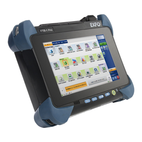
- Page 15 Introducing the FTB-1v2 and FTB-1v2 Pro Front panel Touchscreen Built-in speaker Battery LED Brightness buttons On/Off button (also serves as power LED) Keyboard/ Application switcher button Screen capture button FTB-1v2 and FTB-1v2 Pro...
- Page 16 Introducing the FTB-1v2 and FTB-1v2 Pro Top panel FTB module (shown in grey) Battery compartment door (high-power dual carrier only) FTBx module (shown in grey) Headset/microphone port Built-in power meter and (for any commercially available stereo VFL (optional) headset equipped with a microphone, and having a 3.5 mm connector) Detector port of the power meter...
- Page 17 Introducing the FTB-1v2 and FTB-1v2 Pro Right panel Single carrier and Dual carrier and FTB single-depth FTB double-depth module module AC/DC power adapter connector Security slot for Kensington lock FTB-1v2 and FTB-1v2 Pro...
- Page 18 Introducing the FTB-1v2 and FTB-1v2 Pro Left panel Dual carrier and High-power dual FTB double-depth carrier module Security slot for Kensington lock AC/DC power adapter connector FTB-1v2 and FTB-1v2 Pro...
- Page 19 Introducing the FTB-1v2 and FTB-1v2 Pro Back panel All models, except high-power dual carrier Support High-power dual carrier Battery compartment door Support FTB-1v2 and FTB-1v2 Pro...
-
Page 20: Working With Ftb And Ftbx Modules
Do not attempt to disassemble an FTB module to replace it with an FTBx module. This will result in irreparable damage to both modules and could compromise your safety. To avoid damaging your unit, use it only with modules approved by EXFO. FTB-1v2 and FTB-1v2 Pro... - Page 21 Introducing the FTB-1v2 and FTB-1v2 Pro Working With FTB and FTBx Modules The FTBx modules are inserted into the unit, but the FTB modules are attached to the unit. For more information on how to insert or remove modules, see Inserting and Removing FTBx Test Modules on page 27 and Attaching and Removing FTB Test Modules on page 33.
-
Page 22: Led Indicators Description
Unit is on. Green, blinking Unit is in Sleep mode. Unit is off or in Hibernation mode. There is a major hardware problem with the unit. Contact EXFO. Green The batteries are fully charged. Green, blinking The batteries are charging. - Page 23 Introducing the FTB-1v2 and FTB-1v2 Pro LED Indicators Description Status Meaning The battery level is above the “low-battery threshold”. Yellow The battery level is low. Yellow, blinking The unit and its module would be using more power than what is (when unit is not available from the batteries.
-
Page 24: Function Buttons Description
Introducing the FTB-1v2 and FTB-1v2 Pro Function Buttons Description Function Buttons Description Your unit is equipped with function buttons that give you access to features at all times. The table below shows an overview of their purpose. Button Meaning Adjust the display brightness level. Press the desired button as many times as needed. -
Page 25: Power Sources
Introducing the FTB-1v2 and FTB-1v2 Pro Power Sources Power Sources Your unit operates with the following power sources: AC/DC power adapter (connected to standard power outlet—indoor use only). Compatible car outlet adapter available upon request for all models, except the high-power dual carrier. When it is connected to an external power source with the AC/DC power adapter, the unit will function even if no battery is present. -
Page 26: Software Options For Your Unit
Introducing the FTB-1v2 and FTB-1v2 Pro Software Options for Your Unit Software Options for Your Unit The following software options are offered for the platform itself. Name of Description the Option Enables you to perform ping and trace route tests. SMARTGPS Enables you to retrieve geolocation information (latitude and longitude... -
Page 27: Product Registration
Product Registration Product Registration You can now register your new EXFO products either online or directly from your unit (if it is connected to the Internet), and benefit from every possible opportunity to optimize their performance. By doing so, you will... -
Page 28: Conventions
Introducing the FTB-1v2 and FTB-1v2 Pro Conventions Conventions Before using the product described in this guide, you should understand the following conventions: ARNING Indicates a potentially hazardous situation which, if not avoided, could result in death or serious injury. Do not proceed unless you understand and meet the required conditions. -
Page 29: Safety Information
ARNING Use only accessories designed for your unit and approved by EXFO. For a complete list of accessories available for your unit, refer to its technical specifications or contact EXFO. - Page 30 Safety Information MPORTANT When you see the following symbol on your unit , make sure that you refer to the instructions provided in your user documentation. Ensure that you understand and meet the required conditions before using your product. MPORTANT When you see the following symbol on your unit , it indicates that the unit is equipped with a laser source, or that it can be used...
-
Page 31: Other Safety Symbols On Your Unit
Safety Information Other Safety Symbols on Your Unit Other Safety Symbols on Your Unit One or more of the following symbols may also appear on your unit. Symbol Meaning Direct current Alternating current The unit is equipped with an earth (ground) terminal. The unit is equipped with a protective conductor terminal. -
Page 32: Laser Safety Information
Safety Information Laser Safety Information Laser Safety Information Units with a Built-In VFL Your instrument is in compliance with standards IEC 60825-1: 2007 and 2014. Laser radiation may be encountered at the optical output port. The following label(s) indicate that the product contains a Class 2 source: Affixed to the back of the unit. -
Page 33: Electrical Safety Information
Safety Information Electrical Safety Information Electrical Safety Information ARNING If you need to ensure that the unit is completely turned off, disconnect the power cable and remove the batteries. For more information on how to remove the batteries, see the section about replacing the batteries in this user documentation. - Page 34 Safety Information Electrical Safety Information ARNING Use the external power supply (AC/DC power adapter) indoors only. Never connect the unit to the AC mains (with the AC/DC power adapter) when it is used outdoors. Operation of any electrical instrument around flammable gases ...
- Page 35 All models except the high-power dual carrier: Use only the car outlet adapter designed for your unit and approved by EXFO. The car outlet adapter contains a replaceable fuse. Replace the damaged fuse ONLY with a fuse of the same type: 3AB...
- Page 36 Safety Information Electrical Safety Information Equipment Ratings Temperature unit powered by batteries: 0 °C to 50 °C (32 °F to 122 °F) Operation unit connected to AC power (with AC/DC power adapter): 0 °C to 40 °C (32 °F to 104 °F) Storage unit without batteries: –40 °C to 70 °C (–40 °F to ...
- Page 37 Safety Information Electrical Safety Information Equipment Ratings Measurement category Not rated for measurement categories II, III, or IV Input power all models, except high-power dual carrier: unit: 24 V; 3.75 A AC/DC power adapter: 100 - 240 V; 50/60 Hz; 2.5 A high-power dual carrier: ...
-
Page 39: Getting Started With Your Unit
To avoid damaging your unit, use it only with modules approved by EXFO. FTB-1v2 and FTB-1v2 Pro... - Page 40 Getting Started with Your Unit Inserting and Removing FTBx Test Modules To insert an FTBx module into the FTB-1v2 and FTB-1v2 Pro: 1. Position the unit so that its front panel is facing you. 2. Take the module and place it vertically so that its connector pins are facing downwards and positioned to the left.
- Page 41 Getting Started with Your Unit Inserting and Removing FTBx Test Modules 3. Insert the protruding edges of the module into the grooves of the receptacle’s module slot. 4. Push the module all the way to the bottom of the slot, until it stops. FTB-1v2 and FTB-1v2 Pro...
- Page 42 Getting Started with Your Unit Inserting and Removing FTBx Test Modules 5. Turn the two retaining screws clockwise until they are tightened to secure the module into its “seated” position. The faceplate of the module should be flush with the top panel of the unit. Turn retaining screw clockwise If the unit is already on, the module is detected automatically after the...
- Page 43 Getting Started with Your Unit Inserting and Removing FTBx Test Modules To remove an FTBx module from the FTB-1v2 or FTB-1v2 Pro: 1. From Mini ToolBox X, tap the button. AUTION Once you have pressed the button, wait until the status of the module switches to “Safe to Remove”...
- Page 44 Getting Started with Your Unit Inserting and Removing FTBx Test Modules 4. Hold the module by its sides or by the retaining screws (NOT by the connectors) and pull it out. Note: The retaining screws can be used as handles to pull out the module safely. FTB-1v2 and FTB-1v2 Pro...
-
Page 45: Attaching And Removing Ftb Test Modules
Never remove a module while the unit is turned on. This will result in immediate and irreparable damage to both the module and unit. AUTION To avoid damaging your unit, use it only with modules approved by EXFO. FTB-1v2 and FTB-1v2 Pro... - Page 46 Getting Started with Your Unit Attaching and Removing FTB Test Modules To attach an FTB module to the FTB-1v2 or FTB-1v2 Pro: 1. Position the module so that its back panel rests on a flat surface such as a table. The battery should be visible. Battery 2.
- Page 47 Getting Started with Your Unit Attaching and Removing FTB Test Modules 3. Place the front panel of the unit on the module, making sure that the mating connector of the module is aligned properly with the corresponding slot on the front. The bumpers of the module should be flush with those of the front panel.
- Page 48 Getting Started with Your Unit Attaching and Removing FTB Test Modules 5. Using a flat screwdriver, turn the screws (4) clockwise until they are tightened. This will secure the module into its “seated” position. Screws Turn screws clockwise Screws When you turn on the unit, the module will be detected automatically during the startup sequence.
- Page 49 Getting Started with Your Unit Attaching and Removing FTB Test Modules To remove a module from the FTB-1v2 or FTB-1v2 Pro: 1. Turn off your unit (shutdown), and disconnect it from AC power. 2. Position the unit so that its front panel rests on a flat surface such as a table.
- Page 50 Getting Started with Your Unit Attaching and Removing FTB Test Modules 4. While holding the front panel and the module firmly together, turn the unit over, and position it so that the module (back panel) rests on a flat surface such as a table. 5.
-
Page 51: Positioning Your Unit
Getting Started with Your Unit Positioning Your Unit Positioning Your Unit You can position your unit either vertically (with the screen facing you), or at an angle, using the support on the back panel. All the modules designed for your unit are equipped with such a support that is usable as soon as the module is connected to your unit. -
Page 52: Turning On Your Unit
Getting Started with Your Unit Turning On Your Unit Turning On Your Unit When you turn on the unit for the very first time, a wizard for license agreements and safety instructions is displayed (see the corresponding section for more information). Once you have accepted all the license agreements and confirmed the reading of safety instructions, the main window is displayed. -
Page 53: Turning Off Your Unit
Getting Started with Your Unit Turning Off Your Unit Turning Off Your Unit There are several ways to turn off the unit, including the following: Sleep: keeps the unit’s status information in memory (RAM). The next time you turn your unit on, you will quickly return to your work environment (running applications will still be running). - Page 54 Getting Started with Your Unit Turning Off Your Unit To exit the sleep mode (or hibernation mode) and resume your work: Press the on/off button. To turn off the unit completely from the unit itself: Press the on/off button. To turn off the unit completely from Windows 10: 1.
- Page 55 Getting Started with Your Unit Turning Off Your Unit To define the behavior of the power button: 1. From the main window, tap the System Settings button. 2. Tap Control Panel. 3. Tap Hardware and Sound. FTB-1v2 and FTB-1v2 Pro...
- Page 56 Getting Started with Your Unit Turning Off Your Unit 4. Under Power Options, tap Change what the power buttons do. 5. Tap Changes settings that are currently unavailable. FTB-1v2 and FTB-1v2 Pro...
- Page 57 Getting Started with Your Unit Turning Off Your Unit 6. From the When I press the power button lists, select the desired behavior when the unit is powered by batteries, or by AC current (Shut down option is selected by default in both cases). 7.
- Page 58 Getting Started with Your Unit Turning Off Your Unit To configure your unit to automatically restart after AC power comes back: 1. From the main window, tap the System Settings button. 2. Tap Mini ToolBox X Setup. 3. Select the Power on the unit when AC outlet is connected or after power outage box to enable the corresponding option.
-
Page 59: Configuring Your Unit At First Startup
During the configuration process, you will also be asked to read and accept the Microsoft end-user license agreement (EULA). Once the configuration is complete in Windows, an EXFO wizard will be displayed, allowing you to read the user documentation for important safety information, and to read and accept the EULA related to your unit and instruments. - Page 60 Getting Started with Your Unit Configuring Your Unit At First Startup 4. When the EXFO wizard is displayed, follow the on-screen instructions. 5. Tap Finish to close the wizard and start working. FTB-1v2 and FTB-1v2 Pro...
-
Page 61: Accessing And Exiting Mini Toolbox X
Getting Started with Your Unit Accessing and Exiting Mini Toolbox X Accessing and Exiting Mini Toolbox X By default, Mini Toolbox X is displayed automatically when you turn on the unit. However, you can configure your unit to send Mini Toolbox X to the notification area (see Setting Mini Toolbox X Behavior on page 114). -
Page 62: Starting Module Applications
Getting Started with Your Unit Starting Module Applications Starting Module Applications Your modules can be configured and controlled from their dedicated applications in Mini Toolbox X. To start a module application: 1. If necessary, tap the Modules button to display the modules window. Status of the module (see Understanding Module Statuses on page 51) Inserted or attached module Applications specific to the module... -
Page 63: Understanding Module Statuses
At startup of the corresponding module application. When the module is controlled from external applications such as EXFO Remote ToolBox. Note: This status applies only to FTBx modules. Ejecting The module is being prepared for safe removal from the unit. - Page 64 Getting Started with Your Unit Understanding Module Statuses Status Meaning Safe to remove Note: This status applies only to FTBx modules. The module can now be safely removed from the unit. The applications have finished preparing the module for removal. If you wish to continue working with a module having this status, you can either: Remove it from the unit, and then reinsert it.
-
Page 65: Using The On-Screen (Virtual) Keyboard
Getting Started with Your Unit Using the On-Screen (Virtual) Keyboard Using the On-Screen (Virtual) Keyboard Whenever you need to enter alphanumeric data, you can use the on-screen keyboard. This keyboard supports multilingual features, and functions according to the keyboard settings set in Windows. To use the on-screen keyboard: 1. -
Page 66: Working With Windows 8.1 Pro Or Windows Embedded 8 Standard
Getting Started with Your Unit Working with Windows 8.1 Pro or Windows Embedded 8 Standard Working with Windows 8.1 Pro or Windows Embedded 8 Standard If you are not familiar with Windows 8.1 Pro (FTB-1v2 Pro) or Windows Embedded 8 Standard (FTB-1v2), you may want to visit Microsoft Web site for tutorials as well as detailed information on the features and concepts brought by this operating system. - Page 67 Getting Started with Your Unit Working with Windows 8.1 Pro or Windows Embedded 8 Standard Swipe down: To close windows that do not have a close button. From the top edge of the screen, swipe towards the bottom. Swipe left: To display the Charm bar, which is a special toolbar that ...
-
Page 68: Right-Clicking With The Touchscreen
Getting Started with Your Unit Right-Clicking with the Touchscreen Right-Clicking with the Touchscreen If you are used to work with a mouse, you may find it useful to be able to perform a right-click on your touchscreen. This feature is enabled by default, but you can disable it if you prefer. You can also modify the right-click behavior. -
Page 69: Installing Or Upgrading Exfo Applications
Manager application. If EXFO Software Update is not already available on your unit (shortcut not present on the Windows desktop), you can download it from the EXFO Web site and install it on your unit. In addition to managing the updates of module and instrument... - Page 70 3. Exit Mini Toolbox X and the modules’ applications. 4. On your unit, from Windows desktop, double-tap the EXFO Software Update icon to start the corresponding application. 5. From the EXFO Software Update tool, tap the button to start the process. 6. Follow the on-screen instructions.
-
Page 71: Activating Software Options
However, if you purchase options afterwards, you will have to activate them yourself. Before being able to activate options, you need to contact EXFO with the following information: Purchase order number of the newly purchased options ... - Page 72 Getting Started with Your Unit Activating Software Options To activate software options for your unit or module: 1. Connect a USB memory key to one of the USB ports of your computer. 2. Copy the key file to the USB memory key. 3.
- Page 73 Getting Started with Your Unit Activating Software Options 5. Tap the Platform Options tab or the Module Options tab, depending on the type of options that you want to activate. 6. Use the Browse button to locate the key file that you want to use. 7.
-
Page 74: Installing Third-Party Software On Your Unit
Microsoft license, you should only install antivirus software and the applications provided by EXFO. In all cases, EXFO does not provide any support for the installation, use or troubleshooting of third-party software. Should you need help, refer to the corresponding third-party software documentation or technical support. -
Page 75: Securing Your Unit Using The Kensington Lock
Getting Started with Your Unit Securing your Unit Using the Kensington Lock Securing your Unit Using the Kensington Lock You can connect an optional Kensington lock (security cable) to your unit to prevent theft. To secure your unit: Connect your lock to the security slot located on the side panel of your unit. Right panel Left panel Left panel... -
Page 76: Using A Keyboard, Mouse Or Other Usb Devices
Getting Started with Your Unit Using a Keyboard, Mouse or Other USB Devices Using a Keyboard, Mouse or Other USB Devices Your unit supports many USB devices. The table below gives an overview of the supported USB devices. Device Details Memory key For data transfer between your unit and a computer when you do not have access to a network. - Page 77 RS-232 (serial) ports. For (purchased from more information, see Using the USB to RS-232 EXFO) Adapter on page 163. You can connect several devices at the same time. To use a USB device with your unit: Connect the USB device to any of the USB ports located on the top of the unit (see Top panel on page 4).
-
Page 78: Inserting And Removing Microsd Cards
Getting Started with Your Unit Inserting and Removing microSD Cards Inserting and Removing microSD Cards Your unit is equipped with a slot for microSD cards for extra storage capacity. You can use any commercially available microSD card compatible with the Secure Digital eXtended Capacity (SDXC) format. AUTION Inserting a microSD card upside down could damage both your ... - Page 79 Getting Started with Your Unit Inserting and Removing microSD Cards 2. Position the card vertically so that its smooth edge is on the right and you do not see its gold area. If an arrow is printed on your card, it should point toward the bottom.
- Page 80 Getting Started with Your Unit Inserting and Removing microSD Cards To remove a microSD card from your unit: 1. Locate the microSD card slot on the top panel of your unit. MicroSD card slot 2. Pull the card out of the unit’s microSD card slot. FTB-1v2 and FTB-1v2 Pro...
-
Page 81: Working With Bluetooth Devices
Getting Started with Your Unit Working with Bluetooth Devices Working with Bluetooth Devices ® If you have purchased the Wi-Fi and Bluetooth option, you can use many ® Bluetooth devices with your unit. ® With the supported Bluetooth profiles, you can do the following: Use a wireless mouse and keyboard. -
Page 83: Setting Up Your Ftb-1V2 And Ftb-1V2 Pro
Setting Up Your FTB-1v2 and FTB-1v2 Pro Adjusting Brightness You may want to adjust the display brightness yourself to better fit your work environment or preferences. Values are kept in memory even when you turn the unit off. To adjust the display brightness: From the unit’s front panel, press the (decrease) or (increase) button until the brightness level suits you. -
Page 84: Adjusting Speaker And Microphone Volume
Setting Up Your FTB-1v2 and FTB-1v2 Pro Adjusting Speaker and Microphone Volume Adjusting Speaker and Microphone Volume Your unit is equipped with a built-in speaker, but you can also connect a headset to your unit. To fit your work environment, you may adjust the volume of the speaker, the headphones, or the microphone. - Page 85 Setting Up Your FTB-1v2 and FTB-1v2 Pro Adjusting Speaker and Microphone Volume 3. Tap Windows Mobility Center. 4. Move the Volume slider until the sound level is to your liking. Note: You can also access the sound level slider by tapping the icon from the taskbar.
- Page 86 Setting Up Your FTB-1v2 and FTB-1v2 Pro Adjusting Speaker and Microphone Volume To adjust the microphone volume: 1. Ensure that your headset is connected to the audio port located on the top panel of the unit. Headset/microphone port (for 3.5 mm connector) 2.
- Page 87 Setting Up Your FTB-1v2 and FTB-1v2 Pro Adjusting Speaker and Microphone Volume 4. Tap Hardware and Sound. 5. Under Sound, tap Manage audio devices. FTB-1v2 and FTB-1v2 Pro...
- Page 88 Setting Up Your FTB-1v2 and FTB-1v2 Pro Adjusting Speaker and Microphone Volume 6. Select the Recording tab. 7. Ensure that your microphone is selected, and then tap Properties. FTB-1v2 and FTB-1v2 Pro...
- Page 89 Setting Up Your FTB-1v2 and FTB-1v2 Pro Adjusting Speaker and Microphone Volume 8. From the Levels tab, move the sliders until the settings are to your liking. If the sound coming from your microphone is too low, you may want to adjust the boost level as well. 9.
-
Page 90: Customizing The Right-Click Feature
Setting Up Your FTB-1v2 and FTB-1v2 Pro Customizing the Right-Click Feature Customizing the Right-Click Feature By default, you can perform a “press and hold” action which corresponds to right-clicking with your touchscreen (see Right-Clicking with the Touchscreen on page 56). However, you can disable this feature if you prefer. - Page 91 Setting Up Your FTB-1v2 and FTB-1v2 Pro Customizing the Right-Click Feature 3. Tap Hardware and Sound. 4. Tap Pen and Touch. FTB-1v2 and FTB-1v2 Pro...
- Page 92 Setting Up Your FTB-1v2 and FTB-1v2 Pro Customizing the Right-Click Feature 5. From the list, select Press and hold. 6. Tap Settings. 7. If you want to use the right-click feature with your unit, select the Enable press and hold for right-clicking check box. Clear the check box if you prefer not to use this feature.
- Page 93 Setting Up Your FTB-1v2 and FTB-1v2 Pro Customizing the Right-Click Feature 8. If you want to modify the response time of the right-click, move the Speed or Duration sliders to adjust the configuration to your needs. 9. Tap OK to confirm your changes. FTB-1v2 and FTB-1v2 Pro...
-
Page 94: Enabling Or Disabling The Automatic Logon
Setting Up Your FTB-1v2 and FTB-1v2 Pro Enabling or Disabling the Automatic Logon Enabling or Disabling the Automatic Logon Note: Only administrator-level users can enable or disable the automatic logon feature. You can configure your unit to automatically log on to Windows at startup (no need to select a user and enter a password). - Page 95 Setting Up Your FTB-1v2 and FTB-1v2 Pro Enabling or Disabling the Automatic Logon To enable the automatic logon: 1. From the main window, tap the System Settings button. 2. Tap Automatic Logon. 3. From the User Accounts window, clear the Users must enter a user name and password to use this computer check box.
- Page 96 Setting Up Your FTB-1v2 and FTB-1v2 Pro Enabling or Disabling the Automatic Logon 5. Enter the desired user name (account) and the corresponding password. 6. Tap OK to confirm and to return the System Settings window. At next startup, you will no longer need to specify a user name and password (except if the unit comes back from sleep mode).
- Page 97 Setting Up Your FTB-1v2 and FTB-1v2 Pro Enabling or Disabling the Automatic Logon 3. From the User Accounts window, select the Users must enter a user name and password to use this computer check box. 4. Tap OK to confirm and to return the System Settings window. At next startup, you will have to specify the user name and password.
-
Page 98: Selecting The Startup Applications
Setting Up Your FTB-1v2 and FTB-1v2 Pro Selecting the Startup Applications Selecting the Startup Applications The first time you start your unit, Mini Toolbox X is displayed. You can configure your unit to automatically start any of the available applications as soon as Mini Toolbox X is started. - Page 99 Setting Up Your FTB-1v2 and FTB-1v2 Pro Selecting the Startup Applications 3. Under Module Applications or Other Applications, select the applications you want to start automatically by selecting the corresponding check boxes. 4. Tap OK to use the new settings. Tap Cancel to exit without using the new settings.
-
Page 100: Configuring Network Printers
Setting Up Your FTB-1v2 and FTB-1v2 Pro Configuring Network Printers Configuring Network Printers Your unit supports both (local) USB and network printers (you may have to install specific drivers on your unit). For more information on USB printers connection, see Using a Keyboard, Mouse or Other USB Devices on page 64. - Page 101 Setting Up Your FTB-1v2 and FTB-1v2 Pro Configuring Network Printers 3. Under Hardware and Sound, tap View devices and printers. 4. Tap Add a printer. 5. Follow the on-screen instructions. FTB-1v2 and FTB-1v2 Pro...
-
Page 102: Selecting The Language Of Operation
Setting Up Your FTB-1v2 and FTB-1v2 Pro Selecting the Language of Operation Selecting the Language of Operation You may display the user interface in one of the available languages. The availability of the languages is function of the language group that was installed on your unit at time of purchase. - Page 103 Setting Up Your FTB-1v2 and FTB-1v2 Pro Selecting the Language of Operation 3. Under Clock, Language, and Region, tap Add a language. 4. Select the desired language from the list. 5. Tap Options. FTB-1v2 and FTB-1v2 Pro...
- Page 104 Setting Up Your FTB-1v2 and FTB-1v2 Pro Selecting the Language of Operation 6. If you want to select another keyboard layout than the one that has been added by default, proceed as follows. 6a. Under Input method, tap Add an input method. 6b.
- Page 105 Windows interfaces do not switch to the selected language. They remain in the language configured at time of purchase. However, the EXFO applications are displayed in the selected language (when available). FTB-1v2 and FTB-1v2 Pro...
- Page 106 Setting Up Your FTB-1v2 and FTB-1v2 Pro Selecting the Language of Operation To switch from one of the available input languages to another: 1. From the taskbar, tap the language code to display the list of available input languages. Language code 2.
- Page 107 Setting Up Your FTB-1v2 and FTB-1v2 Pro Selecting the Language of Operation To download language packs: 1. Ensure that your unit has access to the Internet. 2. From the main window, tap the System Settings button. 3. Tap Control Panel. 4.
- Page 108 Setting Up Your FTB-1v2 and FTB-1v2 Pro Selecting the Language of Operation 5. Tap Add a language. 6. Browse the list of languages, and then select the one that you want to use. 7. Tap Open to access the list of sub-languages. FTB-1v2 and FTB-1v2 Pro...
- Page 109 Setting Up Your FTB-1v2 and FTB-1v2 Pro Selecting the Language of Operation 8. Select the desired sub-language, and then tap Add. 9. Select the desired language from the list. 10. Tap Options. FTB-1v2 and FTB-1v2 Pro...
- Page 110 Setting Up Your FTB-1v2 and FTB-1v2 Pro Selecting the Language of Operation 11. Tap Download and install language pack. 12. When the application prompts you to allow the installation, tap Yes. The installation may take a few minutes. 13. When the installation is complete, restart your unit. FTB-1v2 and FTB-1v2 Pro...
-
Page 111: Setting Date And Time Formats
Setting Up Your FTB-1v2 and FTB-1v2 Pro Setting Date and Time Formats Setting Date and Time Formats By default, the dates (short and long) and time are displayed in the formats associated with the global language format (locale). The time can be expressed with a 12- or a 24-hour notation. - Page 112 Setting Up Your FTB-1v2 and FTB-1v2 Pro Setting Date and Time Formats 3. Under Clock, Language, and Region, tap Change date, time, or number formats. 4. Refine the settings according to your needs. 5. Tap Apply to confirm, and then OK to close the window. The new values are taken into account immediately.
-
Page 113: Adjusting The Date, Time And Time Zone
Setting Up Your FTB-1v2 and FTB-1v2 Pro Adjusting the Date, Time and Time Zone Adjusting the Date, Time and Time Zone Note: Only administrator-level users can adjust the date and time. All users can modify the time zone. The current date and time are displayed at the bottom of the main window. When saving results, the unit also saves the corresponding date and time. - Page 114 Setting Up Your FTB-1v2 and FTB-1v2 Pro Adjusting the Date, Time and Time Zone 3. Tap Clock, Language, and Region. 4. Under Date and Time, tap Set the time and date. FTB-1v2 and FTB-1v2 Pro...
- Page 115 Setting Up Your FTB-1v2 and FTB-1v2 Pro Adjusting the Date, Time and Time Zone 5. Tap Change date and time or Change time zone, depending on the settings that you want to modify. 6. Modify the settings according to your needs, and then tap OK. 7.
-
Page 116: Configuring The Power Management Options
Setting Up Your FTB-1v2 and FTB-1v2 Pro Configuring the Power Management Options Configuring the Power Management Options To help you get the optimum performance out of your unit, it comes with predefined sets of parameters (plans) to manage power. When you do not use the unit for a while, the display may be turned off to save power. - Page 117 Setting Up Your FTB-1v2 and FTB-1v2 Pro Configuring the Power Management Options To select a power plan: 1. From the main window, tap the System Settings button. 2. Tap Control Panel. 3. Tap Hardware and Sound > Power Options. FTB-1v2 and FTB-1v2 Pro...
- Page 118 Setting Up Your FTB-1v2 and FTB-1v2 Pro Configuring the Power Management Options 4. If necessary, tap Change settings that are currently unavailable. 5. From the list of available power plans, select the desired set of parameters. 6. Close the window. The new values are taken into account immediately.
- Page 119 Setting Up Your FTB-1v2 and FTB-1v2 Pro Configuring the Power Management Options To create a power plan: 1. From the main window, tap the System Settings button. 2. Tap Control Panel. 3. Tap Hardware and Sound > Power Options. FTB-1v2 and FTB-1v2 Pro...
- Page 120 Setting Up Your FTB-1v2 and FTB-1v2 Pro Configuring the Power Management Options 4. From the list on the left, tap Create a power plan. 5. Select a power plan that will serve as a basis. 6. Enter a name, and then tap Next. FTB-1v2 and FTB-1v2 Pro...
- Page 121 Setting Up Your FTB-1v2 and FTB-1v2 Pro Configuring the Power Management Options 7. Modify the parameters to suit your needs. 8. Tap Create. FTB-1v2 and FTB-1v2 Pro...
- Page 122 Setting Up Your FTB-1v2 and FTB-1v2 Pro Configuring the Power Management Options To modify or delete an existing power plan: 1. From the main window, tap the System Settings button. 2. Tap Control Panel. 3. Tap Hardware and Sound > Power Options. FTB-1v2 and FTB-1v2 Pro...
- Page 123 Setting Up Your FTB-1v2 and FTB-1v2 Pro Configuring the Power Management Options 4. From the list of available power plans, locate the set of parameters that you want to modify or delete. Note: You can only delete custom power plans, not predefined ones. If the custom power plan that you want to delete is currently in use, you must select another plan first.
- Page 124 Setting Up Your FTB-1v2 and FTB-1v2 Pro Configuring the Power Management Options 6. If you want to modify the parameters, proceed as follows: 6a. If necessary, tap Change settings that are currently unavailable. 6b. Modify the parameters to your needs. 6c.
- Page 125 Setting Up Your FTB-1v2 and FTB-1v2 Pro Configuring the Power Management Options 7. If you want to delete the power plan, tap Delete this plan, and then confirm the deletion. 8. Close the window. The changes are taken into account immediately. FTB-1v2 and FTB-1v2 Pro...
-
Page 126: Setting Mini Toolbox X Behavior
Setting Up Your FTB-1v2 and FTB-1v2 Pro Setting Mini Toolbox X Behavior Setting Mini Toolbox X Behavior You can specify how Mini Toolbox X behaves when the application is started, minimized or closed. To set the Mini Toolbox X behavior: 1. - Page 127 Setting Up Your FTB-1v2 and FTB-1v2 Pro Setting Mini Toolbox X Behavior 3. Select the items corresponding to the desired behavior. Hide Mini ToolBox X in the notification area when minimized: If this option is selected, the Mini Toolbox X icon appears in the notification area (where the clock is located) when you minimize the window.
-
Page 128: Configuring The Internet Options
Setting Up Your FTB-1v2 and FTB-1v2 Pro Configuring the Internet Options Configuring the Internet Options You can browse the Web directly from your unit, provided that you have access to an Internet connection and that the Internet options are configured properly. If you are not sure about how you should configure your Internet access, contact your network administrator. - Page 129 Setting Up Your FTB-1v2 and FTB-1v2 Pro Configuring the Internet Options 3. Tap Network and Internet. 4. Tap Internet Options. FTB-1v2 and FTB-1v2 Pro...
- Page 130 Setting Up Your FTB-1v2 and FTB-1v2 Pro Configuring the Internet Options 5. Go to the Connections tab. 6. Modify the settings using the information provided by your network administrator. 7. Tap OK to return to the Control Panel window. FTB-1v2 and FTB-1v2 Pro...
-
Page 131: Getting Ready To Retrieve Geolocation Information
Setting Up Your FTB-1v2 and FTB-1v2 Pro Getting Ready to Retrieve Geolocation Information Getting Ready to Retrieve Geolocation Information With your unit and a smart device properly configured, you can retrieve geolocation information (latitude and longitude coordinates) to identify the position of your unit.This geolocation information can then be saved along with test results, or viewed in the GPS Coordinates Viewer (see Retrieving the GPS Location of Your Unit on page 133). - Page 132 3. If it is not done already, install EXFO Link: 3a. Ensure you have access to an Internet connection. 3b. Ensure that you have a Google account to be able to download EXFO Link.
- Page 133 Setting Up Your FTB-1v2 and FTB-1v2 Pro Getting Ready to Retrieve Geolocation Information 4. Start the EXFO Link application. 5. If it is not done already, enable the geolocation feature: 5a. From the main window, tap Note: Depending on the smart device you are using, the application settings could be found in the menu button instead.
- Page 134 Getting Ready to Retrieve Geolocation Information 5c. Under GENERAL SETTINGS, select the Geolocation option. Note: For more information on how to modify other settings related to geolocation, refer to the EXFO Link user documentation. 5d. Tap to return to the main window.
- Page 135 Setting Up Your FTB-1v2 and FTB-1v2 Pro Getting Ready to Retrieve Geolocation Information To connect your unit to the mobile hotspot: 1. On your smart device, ensure that EXFO Link is running, configured properly, and that the mobile hotspot that you have created is available.
-
Page 136: Configuring Parameters Via Windows Mobility Center
Setting Up Your FTB-1v2 and FTB-1v2 Pro Configuring Parameters via Windows Mobility Center Configuring Parameters via Windows Mobility Center For a quick access to various parameters such as the volume or power plans, you may want to use the Windows Mobility Center. To configure the parameters via Windows Mobility Center: 1. -
Page 137: Setting Other Parameters
Setting Up Your FTB-1v2 and FTB-1v2 Pro Setting Other Parameters 3. Set the parameters as desired. Note: To adjust the brightness, from the unit’s front panel, press the button until the brightness level suits you. Setting Other Parameters You can also configure many other parameters via the Control Panel window. -
Page 139: Working With Your Unit
Working with Your Unit Printing Documents You can print documents and images directly from your unit by using either the provided PDF creation tool or an external printer (for printing on paper). You can view the PDF files from your unit, using the provided PDF reader. For more information, see Viewing PDF Files on page 128. -
Page 140: Viewing Pdf Files
Working with Your Unit Viewing PDF Files Viewing PDF Files You can view PDF files directly from your unit using the provided PDF file viewer. For more information on the available features for this viewer, refer to the PDF viewer online help. Note: You may need a connection to the Internet to access the PDF viewer online help. -
Page 141: Taking Screen Captures
Working with Your Unit Taking Screen Captures Taking Screen Captures You can take captures of what is displayed on your screen, directly from your unit. This could be useful for troubleshooting when you need another person to have a look at a specific configuration or problem. You could also use this tool for training purposes. -
Page 142: Browsing The Web
Working with Your Unit Browsing the Web Browsing the Web You can browse the Web directly from your unit, provided that you have access to an Internet connection. If you need to modify the Internet options, see Configuring the Internet Options on page 116. -
Page 143: Accessing The Internet With A Mobile Broadband Usb Modem Key
Working with Your Unit Accessing the Internet with a Mobile Broadband USB Modem Key Accessing the Internet with a Mobile Broadband USB Modem Key Note: Only administrator-level users can install software. However, when the installation is complete, all users will have the possibility to access the Internet with a USB modem key. - Page 144 Working with Your Unit Accessing the Internet with a Mobile Broadband USB Modem Key To work with a mobile broadband USB modem key: 1. If necessary, turn on your unit and wait for the startup sequence to complete. 2. If necessary, connect the USB modem key to one of the USB ports of your unit.
-
Page 145: Retrieving The Gps Location Of Your Unit
Working with Your Unit Retrieving the GPS Location of Your Unit Retrieving the GPS Location of Your Unit With your unit, a smart device, and the provided GPS utility, you can retrieve the latitude and longitude coordinates of your unit as well as the date and time of the reading. - Page 146 1. If necessary, turn on your unit and wait for the startup sequence to complete. 2. On your smart device, ensure that EXFO Link is running and that the mobile hotspot that you have created is available. 3. Connect your unit to the mobile hotspot as you would do with any other wireless network.
- Page 147 Working with Your Unit Retrieving the GPS Location of Your Unit Note: If you see “GPS not detected” at the bottom of the GPS Coordinates window, this could mean that either the SMARTGPS option is not activated on your unit, or there is a problem with the link to the mobile hotspot. When geolocation information is available, the utility will display “Receiving coordinates”.
-
Page 148: Managing Favorites
Working with Your Unit Managing Favorites Managing Favorites For a quicker access to the applications that you use most often, you may want to build your own list of favorite applications (Favorites). You can add and remove Favorites from the list. You can also import and export lists of Favorites, which could be useful for backup and recovery purposes, or to share the same Favorites among several units. - Page 149 Working with Your Unit Managing Favorites 4. Tap Browse to locate the desired application. 5. Type a name for the new Favorite. 6. Tap OK to confirm the location and name. 7. Repeat the previous steps with all the Favorites that you want to add. 8.
- Page 150 Working with Your Unit Managing Favorites 3. Tap the icon corresponding to the Favorite that you want to remove from the list. 4. Tap Remove. Note: The application will not prompt you to confirm the removal of the Favorite from the list. Removing a Favorite from the list does not uninstall the application from the unit.
- Page 151 Working with Your Unit Managing Favorites To work with Favorites: 1. From the main window, tap the Favorites button. 2. Tap the icon corresponding to the application that you want to use. To export the list of Favorites: 1. From the main window, tap the Favorites button. 2.
- Page 152 Working with Your Unit Managing Favorites 3. Tap Export. FTB-1v2 and FTB-1v2 Pro...
- Page 153 Working with Your Unit Managing Favorites 4. Select a location and type a name for the Favorites list. 5. Tap Save. 6. Tap OK to apply the changes and close the window. FTB-1v2 and FTB-1v2 Pro...
- Page 154 Working with Your Unit Managing Favorites To import a list of Favorites: 1. From the main window, tap the Favorites button. 2. Tap Favorites Management. 3. Tap Import. FTB-1v2 and FTB-1v2 Pro...
- Page 155 Working with Your Unit Managing Favorites 4. Select the desired Favorites list. 5. Tap Open. 6. Tap OK to apply the changes and close the window. FTB-1v2 and FTB-1v2 Pro...
-
Page 156: Using The Calculator
Working with Your Unit Using the Calculator Using the Calculator You can use Microsoft Calculator directly from your unit. To use the Calculator: 1. From the main window, tap the Utilities button. 2. Tap Calculator. Using the Text Editor You can use Microsoft Notepad directly from your unit. To use the text editor: 1. -
Page 157: Accessing Other Tools
Working with Your Unit Accessing Other Tools Accessing Other Tools Your unit comes with various tools that can help you better analyze or manage your data. You have also access to free tools such as Wireshark to help you troubleshoot networks. For more information, refer to the online help provided with these tools, when applicable. -
Page 159: Using The Optional Built-In Power Meter And Vfl
Using the Optional Built-In Power Meter and VFL The FTB-1v2 and FTB-1v2 Pro can be equipped with an optical power meter and a visual fault locator (VFL). With the power meter, you can measure absolute power (dBm or W) or insertion loss (dB). - Page 160 Using the Optional Built-In Power Meter and VFL To access the built-in power meter or the VFL: From the main window, tap Power Meter and VFL. Note: The Power Meter and VFL button is only visible if your unit is equipped with a power meter and a VFL.
-
Page 161: Inspecting Fibers With A Probe
Inspecting Fibers with a Probe The fiber inspection probe (FIP) is used to find dirty or damaged connectors by displaying an enlarged view of the connector surface. You can connect an FIP to your unit to view fiber ends. MPORTANT Only the probes of the FIP-400B series are supported on your unit. -
Page 163: Managing Data
Managing Data You can copy, move, rename, delete files and folders directly on your unit. You can transfer files from your unit to a USB memory key or a computer. You can also transfer data from a storage device or a computer to your unit. Your unit is equipped with the following ports and devices for data transfer: A microSD card slot to insert a memory card ... -
Page 164: Viewing Disk Space And Managing Files
Managing Data Viewing Disk Space and Managing Files Viewing Disk Space and Managing Files To help you manage the data that is stored on your unit, you can easily view the remaining disk space. You can also copy, move, rename, delete files and folders directly from your unit. -
Page 165: Transferring Data Via The Bluetooth Technology
Managing Data Transferring Data via the Bluetooth Technology Transferring Data via the Bluetooth Technology ® If you have purchased the Wi-Fi and Bluetooth option, you can transfer data between your unit and a computer (or another device such as a ®... - Page 166 Managing Data Transferring Data via the Bluetooth Technology The procedure presented hereafter explains how to transfer data from your unit to a computer. Note: If you transfer files from a computer to your unit, they will be sent automatically to the This PC\Documents\Bluetooth Folder on your unit. To configure your unit and the computer for transfer: 1.
- Page 167 Managing Data Transferring Data via the Bluetooth Technology 1d. From the Share tab, ensure that the Allow remote devices to browse, send, and receive pictures, music, and other files check box is selected. 1e. Tap OK to confirm. 2. Configure the computer as follows: ®...
- Page 168 Managing Data Transferring Data via the Bluetooth Technology ® To transfer data via the Bluetooth technology: 1. Pair your computer with your unit as follows. ® 1a. From the notification area, tap the Bluetooth icon. 1b. Tap Add a Bluetooth Device. ®...
- Page 169 Managing Data Transferring Data via the Bluetooth Technology 1d. On the FTB-1v2 running Windows 10 or FTB-1v2 Pro, tap Pair. On the FTB-1v2 running Windows Embedded 8 Standard, the application tries to establish the pairing automatically. Note: If the computer or device that you want to select is already paired, you must remove the pairing first with the Remove device button.
- Page 170 Managing Data Transferring Data via the Bluetooth Technology 2c. Select Send files. 2d. Select the desired computer, and then tap Next. FTB-1v2 and FTB-1v2 Pro...
- Page 171 Managing Data Transferring Data via the Bluetooth Technology 2e. Tap the Browse button to select the file that you want to transfer, and then tap Next. 2f. Tap Finish when the transfer is complete. FTB-1v2 and FTB-1v2 Pro...
-
Page 172: Connecting To A Wireless Network
Managing Data Connecting to a Wireless Network Connecting to a Wireless Network If you have purchased the Wi-Fi option, you can connect to a wireless network and benefit from all resources that are available on this network. You can transfer data exactly as you would do from an Ethernet network. By default, the internal wireless module is enabled, but not connected to a network. - Page 173 Managing Data Connecting to a Wireless Network 2. In Windows 10, tap Network. In Windows 8.1 Pro or in Windows Embedded 8 Standard, tap Settings, and then the icon. FTB-1v2 and FTB-1v2 Pro...
- Page 174 Managing Data Connecting to a Wireless Network 3. Tap the item corresponding to the wireless network to which you want to connect. 4. Tap Connect. 5. If the network is protected by a network security key (password) enter it in the corresponding box and tap Next. 6.
-
Page 175: Using The Usb To Rs-232 Adapter
If you want to transfer data between your unit and a device that is only equipped with RS-232 (serial) ports, you have to use a USB/RS-232 adapter (sold by EXFO). Once the adapter has been detected, the unit assigns it a COM port number (for some adapters, values do not begin at COM 1). - Page 176 Managing Data Using the USB to RS-232 Adapter To use the USB/RS-232 adapter: 1. Turn on both the unit and the serial device. 2. Connect as shown. You can connect the USB end of the adapter to any of the USB ports. Serial end USB end Serial...
- Page 177 Managing Data Using the USB to RS-232 Adapter 3. From your unit, retrieve the COM port of the adapter as follows: 3a. From the main window, tap the System Settings button. 3b. Tap Control Panel. 3c. Tap Hardware and Sound. FTB-1v2 and FTB-1v2 Pro...
- Page 178 Managing Data Using the USB to RS-232 Adapter 3d. Under Devices and Printers, tap Device Manager. 3e. Expand the Ports (COM & LPT) list to retrieve the COM port number that has been assigned to the adapter (identified as USB Serial Port) and write it down.
- Page 179 Managing Data Using the USB to RS-232 Adapter 4. From your unit, configure the communication parameters as follows: 4a. From the main window, tap the Utilities button. 4b. Tap PuTTY. 4c. Configure the parameters. Tree view From the tree view, select Connection > Serial and set the ...
- Page 180 Managing Data Using the USB to RS-232 Adapter 5. From the device, set the communications parameters. IMPORTANT To be able to establish a communication between the unit and the device, you must set the following parameters to the same values as those defined on your unit: Speed ...
-
Page 181: Freeing Up Disk Space With The Disk Cleanup Utility
Managing Data Freeing Up Disk Space with the Disk Cleanup Utility Freeing Up Disk Space with the Disk Cleanup Utility If you need to free up disk space on your unit, you can use the Windows Disk Cleanup utility. With this utility, you can clear files such as the Internet temporary files, files from the Recycle bin, or even files that you no longer need from the previous installation. - Page 182 Managing Data Freeing Up Disk Space with the Disk Cleanup Utility 3. Tap Control Panel. 4. Tap System and Security. FTB-1v2 and FTB-1v2 Pro...
- Page 183 Managing Data Freeing Up Disk Space with the Disk Cleanup Utility 5. Tap Administrative Tools, and then double-tap Disk Cleanup. 6. If you want to remove system files such as the files from the Windows.old folder, tap Clean up system files. FTB-1v2 and FTB-1v2 Pro...
- Page 184 Managing Data Freeing Up Disk Space with the Disk Cleanup Utility 7. When the folders are displayed, select the check box corresponding to the desired item. If you want to clear the Windows.old folder, select the Previous Windows installation(s) check box. Ensure that all the other check boxes are cleared.
-
Page 185: Enabling Or Disabling The Wireless Communication
Managing Data Enabling or Disabling the Wireless Communication Enabling or Disabling the Wireless Communication ® By default, the internal Wi-Fi and Bluetooth modules are enabled on your ® unit if you have purchased the Wi-Fi and Bluetooth options. However, if you do not intend to work with a wireless network or to ®... - Page 186 Managing Data Enabling or Disabling the Wireless Communication To enable or disable the wireless communication in Windows 10: 1. From the notification area, tap the notification preview icon. 2. Set the wireless communication parameters as needed. ® If you want to set the parameters for the Wi-Fi and the Bluetooth ...
- Page 187 Managing Data Enabling or Disabling the Wireless Communication To enable or disable the wireless communication in Windows 8.1 Pro: 1. From the right side of the screen, swipe left to display the Charm bar. 2. Tap Settings, and then the icon.
- Page 188 Managing Data Enabling or Disabling the Wireless Communication To enable or disable the wireless communication in Windows Embedded 8 Standard: 1. From the right side of the screen, swipe left to display the Charm bar. 2. Tap Settings, and then Change PC Settings. 3.
- Page 189 Managing Data Enabling or Disabling the Wireless Communication 4. Set the wireless communication parameters as needed. If you want to set the parameters for the Wi-Fi device and the mobile broadband USB key at the same time, set the Airplane mode slider to the Off position to enable the communication, or to the On position to disable it.
-
Page 190: Connecting To A Vpn From Your Unit
VPN may vary. For information on the configuration specific to your network, contact your network administrator. MPORTANT EXFO does not provide any VPN clients. You must either use one of the VPN clients available directly in Windows or provide the installation files for another VPN client yourself. - Page 191 Managing Data Connecting to a VPN from Your Unit MPORTANT To avoid communication problems between the VPN client and the VPN server, ensure that the date set on your unit corresponds to the current date. To add a VPN connection: 1.
- Page 192 Managing Data Connecting to a VPN from Your Unit 4. Under Network and Sharing Center, tap View network status and tasks. 5. Tap Set up a new connection or network. FTB-1v2 and FTB-1v2 Pro...
- Page 193 Managing Data Connecting to a VPN from Your Unit 6. Tap Connect to a workplace, and then tap Next. 7. Follow the on-screen instructions. FTB-1v2 and FTB-1v2 Pro...
- Page 194 Managing Data Connecting to a VPN from Your Unit To install a VPN client on your unit (Windows 10 and Windows 8.1 Pro only): 1. Start the installation of the VPN client using the files and settings provided by your network administrator. 2.
- Page 195 Managing Data Connecting to a VPN from Your Unit 4. Under Network and Sharing Center, tap Connect to a network. 5. From the list displayed at the right of the screen, select the desired VPN connection. 6. If your unit is running Windows 10, a new window will open. Select the desired VPN connection from the list.
-
Page 197: Accessing Your Unit Remotely
Accessing Your Unit Remotely You can access your unit remotely from a computer using the Remote Desktop Connection application. You can access your unit remotely from a computer using either the Remote Desktop Connection application or a VNC viewer. The table below presents the differences between the two applications. Remote Desktop Characteristic VNC Viewer... -
Page 198: Working With Remote Desktop
Accessing Your Unit Remotely Working with Remote Desktop Working with Remote Desktop By default, the remote access to your unit with Remote Desktop is not enabled. However, once you enable it, all the accounts with administrator rights can use Remote Desktop. If you want accounts with limited rights to be able to use it as well, you must specifically grant them access. - Page 199 Accessing Your Unit Remotely Working with Remote Desktop To allow the remote access to your unit with Remote Desktop: 1. From the main window, tap the System Settings button. 2. Tap Remote Session. 3. Under Remote Desktop, select Allow remote connections to this computer.
- Page 200 Accessing Your Unit Remotely Working with Remote Desktop To access your unit remotely with Remote Desktop: 1. Connect both the computer and your unit to the same network and make sure they can “see” each other as network restrictions might prevent them from communicating.
- Page 201 Accessing Your Unit Remotely Working with Remote Desktop 5. From the computer, open the Remote Desktop Connection window. If your computer runs Windows Vista or Windows 7: On the taskbar, click Start, then select All Programs > Accessories > Remote Desktop Connection.
- Page 202 Accessing Your Unit Remotely Working with Remote Desktop Allowing Users with Limited Accounts to Use Remote Desktop By default, only the accounts with administrator rights can use Remote Desktop. However, you can assign extra user rights to accounts with limited rights so that they can also use Remote Desktop. To allow a user with limited accounts to use Remote Desktop: 1.
- Page 203 Accessing Your Unit Remotely Working with Remote Desktop 3. Under Remote Desktop, select Allow remote connections to this computer. 4. Tap Select Users. 5. From the Remote Desktop Users dialog box, tap Add. FTB-1v2 and FTB-1v2 Pro...
- Page 204 Accessing Your Unit Remotely Working with Remote Desktop 6. From the Select Users dialog box, tap Advanced. 7. Tap Find Now to let the system find and display the list of users. 8. Select the user to which you want to grant access rights, and then tap FTB-1v2 and FTB-1v2 Pro...
- Page 205 Accessing Your Unit Remotely Working with Remote Desktop 9. From the list of users, select the user that you have just added, and then tap OK. 10. Repeat steps 7 to 9 with all the users to which you want to grant access rights.
- Page 206 Accessing Your Unit Remotely Working with Remote Desktop Preventing Users from Connecting with Remote Desktop You can also configure the unit to prevent users to access it using Remote Desktop. However, all users having administrator user rights will be able to modify this setting at any time.
- Page 207 Accessing Your Unit Remotely Working with Remote Desktop 3. Under Remote Desktop, select Don’t allow remote connections to this computer. 4. Tap OK to confirm the changes and return to the System Settings window. FTB-1v2 and FTB-1v2 Pro...
-
Page 208: Working With Vnc
Accessing Your Unit Remotely Working With VNC Working With VNC The control of your unit with VNC requires the UltraVNC Server (already installed on your unit) and a VNC viewer (that you must install on your computer). To be able to connect to the unit using VNC, you must: Know the IP address of the unit and provide it in the connection ... - Page 209 Accessing Your Unit Remotely Working With VNC Configuring the VNC Server The UltraVNC Server is already installed on your unit. By default, the server is configured to accept secured connections only. This means that you must configure a password before establishing a connection between a computer and your unit.
- Page 210 Accessing Your Unit Remotely Working With VNC 4. From the shortcut menu, tap Admin Properties. 5. Depending on the type of connection that you want, under Authentication, enter a value in the VNC Password or View-Only Password box. Note: The VNC and view-only passwords are independent of each other. They do not have to be identical.
- Page 211 If no VNC viewer is already installed on your computer, you can download the UltraVNC Viewer from the Web for free. MPORTANT EXFO does not provide licenses for UltraVNC Viewer. Always ensure that you are entitled to install it on your computer. To install the UltraVNC Viewer on your computer: 1.
- Page 212 Accessing Your Unit Remotely Working With VNC Connecting to Your Unit with VNC Once the UltraVNC Viewer is installed on your computer, you are ready to access your unit remotely. To connect to your unit with UltraVNC: 1. Connect both the computer and your unit to the same network and make sure they can “see”...
- Page 213 Accessing Your Unit Remotely Working With VNC 5. Tap Platform. 6. Scroll down until you can see the IP address. 7. Write down the IP address, and then close the window. Note: It may take a few seconds before you see the IP address on the list. FTB-1v2 and FTB-1v2 Pro...
- Page 214 Accessing Your Unit Remotely Working With VNC 8. From the main window, tap the System Settings button. 9. Tap UltraVNC Server to start the server. Note: For security reasons, the UltraVNC Server is not started automatically. However, if you prefer that your unit remains ready for remote connections at all times, you can install the corresponding service (right-click the UltraVNC icon, and then tap Install Service).
- Page 215 Accessing Your Unit Remotely Working With VNC 11. In the VNC Server list, type the IP address of your unit that you wrote down at step 7. Note: The appearance of the UltraVNC Viewer window may vary depending on the version of the viewer that you have. 12.
-
Page 216: Adding Exceptions To The Firewall
Accessing Your Unit Remotely Adding Exceptions to the Firewall Adding Exceptions to the Firewall Note: Only administrator-level users can add exceptions to the firewall. Your unit is protected by the Microsoft firewall to prevent unauthorized access when it is connected to a network or to the Internet. The firewall has been preconfigured so that all the applications that come with your unit work properly. - Page 217 Accessing Your Unit Remotely Adding Exceptions to the Firewall 4. Under Windows Firewall, tap Allow an app through Windows Firewall. 5. Tap the Change settings button. FTB-1v2 and FTB-1v2 Pro...
- Page 218 Accessing Your Unit Remotely Adding Exceptions to the Firewall 6. Tap the Allow another app button. 7. Select the desired application from the list, and then tap Add. FTB-1v2 and FTB-1v2 Pro...
- Page 219 Accessing Your Unit Remotely Adding Exceptions to the Firewall 8. Ensure that the Private and Public settings of the added application suit your needs. 9. When you have finished, tap OK to confirm the changes and return to the Control Panel window. FTB-1v2 and FTB-1v2 Pro...
-
Page 221: 10 Testing Network Connections
10 Testing Network Connections Note: This function is available with the optional IPT software package only. The two most common basic tests widely used in networking are the ping test and the trace route test. With these tests, you can ensure that IP packets travel as expected from a local host to a remote host and vice versa. - Page 222 Testing Network Connections Performing a Ping Test To perform a ping test: 1. From the main window, tap Test Tools. 2. Tap IP Tools. 3. From IP Testing Tools, select the Ping tab. FTB-1v2 and FTB-1v2 Pro...
- Page 223 Testing Network Connections Performing a Ping Test 4. Enter a URL or an IP address to reach. You can tap the Default button to use the unit's default ping address. The default value cannot be configured. 5. Set the other parameters: Number of packets to send ...
-
Page 224: Performing A Trace Route Test
Testing Network Connections Performing a Trace Route Test Performing a Trace Route Test The trace route test is used to evaluate the average number of nodes that are required to reach the final host. It is often used to troubleshoot networks (identify accesses blocked by firewalls or routing problems). - Page 225 Testing Network Connections Performing a Trace Route Test To perform a trace route test: 1. From IP Testing Tools, select the Trace Route tab. 2. Enter an URL or an IP address to reach. You can tap the Default button to use the unit's default trace route address.
-
Page 226: Exporting The Results
Testing Network Connections Exporting the Results Exporting the Results When a test is complete, you can export the results of the current test page. If you want to keep your results for future use, you must export them because result files cannot be opened directly from your unit. Results are sent to a text file. -
Page 227: 11 Preparing For Automation
Note: To have access to automation features on an FTB-1v2 unit, you must purchase the Automation option. EXFO supplies commands that follow the guidelines determined by the SCPI consortium for many instruments. EXFO also supplies COM properties and events allowing you to build your own application. The instruments... - Page 228 Preparing for Automation The choice of a technology depends on your particular needs. Communication Characteristics ActiveX (COM) Allows you to develop an application that will run locally on your unit within Windows. Best approach when speed is your top priority (no physical ...
-
Page 229: Linking Units With The Ethernet Port
Your unit is not equipped with a serial (RS-232) port, but you can connect a USB to RS-232 adapter (sold by EXFO) to your one of the USB ports of your unit if you wish to send and receive data via RS-232. Refer to the Microsoft Windows documentation for information about serial port settings and possibilities. -
Page 230: Getting Optimum Performance From Your Unit
Preparing for Automation Getting Optimum Performance from Your Unit Getting Optimum Performance from Your Unit Several factors influence the data transfer rate of your unit. The information presented hereafter will help you get the best transfer rate possible. Output unit (RS-232, ActiveX and TCP/IP): Your unit can return results ... - Page 231 Preparing for Automation Getting Optimum Performance from Your Unit Output format (RS-232, ActiveX and TCP/IP): Your unit provides the following output formats for measurement results: ASCii PACKed Generally, the PACKed format allows to pass three to four times more information than the ASCii format for the same transfer rate.
-
Page 232: Changing Communication Settings
Preparing for Automation Changing Communication Settings Changing Communication Settings Communication settings cannot be modified without turning on your unit and starting Mini ToolBox X. 1. Tap the System Settings button, then tap Instrument Control Configuration. 2. Tap Change settings, and then, when the application prompts you to authorize the changes to your unit, tap Yes. - Page 233 Preparing for Automation Changing Communication Settings 3. If you want to send SCPI commands to your modules, select the Allow automation on instruments check box. Clear the check box if you prefer to block automation on your unit. Note: If you allow automation, all modules in your unit will be initialized upon startup so you are ready to send remote commands.
- Page 234 Preparing for Automation Changing Communication Settings 4. Under Communication Type, select ActiveX, RS-232, or TCP/IP. For more information on the choice of a particular type, see the table on page 216. Note: If the selected communication type does not match the protocol that will actually be used, an error message is displayed when attempting to control the instruments.
- Page 235 Preparing for Automation Changing Communication Settings For TCP/IP Port 5024—used to connect over Telnet. Port 5025—used for socket (raw) connections; compatible with IVI drivers. To automatically close the TCP/IP Allowed period of inactivity, in session after the specified period minutes.
- Page 236 Preparing for Automation Changing Communication Settings To revert to default RS-232 settings: 1. Tap the Default settings button. 2. Tap Apply to confirm your changes. FTB-1v2 and FTB-1v2 Pro...
-
Page 237: Configuring Dcom Access To Your Unit
DCOM technology allows to control devices and optical instruments via Ethernet. The EXFO IcSCPIAccess Class component provided with your unit acts as a communication link between a client application and EXFO’s Instrument Control. For more information, refer to the EXFO Remote Control Demo available in EXFO Apps, at http://www.exfo.com/software/exfo-apps/exfo-remote-control-demo. - Page 238 Preparing for Automation Configuring DCOM Access to Your Unit Setting the General Security Parameters To enable DCOM access to your unit, you must first set the general security parameters. Note: To modify the security parameters, you need administrator access rights. To set the general security parameters: 1.
- Page 239 Preparing for Automation Configuring DCOM Access to Your Unit 7. In the My Computer Properties dialog box, tap the COM Security tab. 8. Under Access Permissions, tap Edit Limits. FTB-1v2 and FTB-1v2 Pro...
- Page 240 Preparing for Automation Configuring DCOM Access to Your Unit 9. In the Access Permission dialog box, ensure that the Distributed COM Users group appears in the Group or user names list. 10. Tap OK. 11. In the My Computer Properties dialog box, tap the COM Security tab. FTB-1v2 and FTB-1v2 Pro...
- Page 241 Preparing for Automation Configuring DCOM Access to Your Unit 12. Under Launch and Activation Permissions, tap Edit Limits. FTB-1v2 and FTB-1v2 Pro...
- Page 242 Preparing for Automation Configuring DCOM Access to Your Unit 13. In the Access Permission dialog box, ensure that the Distributed COM Users group appears in the Group or user names list. You can now allow users to access general DCOM services on your unit. You can either: Add a user to the Distributed COM Users group (refer to Microsoft ...
- Page 243 Preparing for Automation Configuring DCOM Access to Your Unit To add a user explicitly: 1. In the My Computer Properties dialog box, tap the COM Security tab. 2. Under Access Permission, tap Edit Limits. 3. In the Access Permission dialog box, tap Add. FTB-1v2 and FTB-1v2 Pro...
- Page 244 Preparing for Automation Configuring DCOM Access to Your Unit 4. In the Select Users or Groups dialog box, under Enter the object names to select, type the name of the user to whom you want to give access rights. 5. Tap OK. FTB-1v2 and FTB-1v2 Pro...
- Page 245 Preparing for Automation Configuring DCOM Access to Your Unit 6. Confirm the newly added user has remote access permission as follows: 6a. In the Access Permission dialog box, select the name of the new user. 6b. Under Permissions for (new user), ensure Allow is selected for Remote Access.
- Page 246 Preparing for Automation Configuring DCOM Access to Your Unit 9. In the Launch and Activation Permission dialog box, tap Add. 10. In the Select Users or Groups dialog box, under Enter the object names to select, type the name of the user to whom you want to give start and activation access rights.
- Page 247 Preparing for Automation Configuring DCOM Access to Your Unit 12. Confirm the newly added user has Remote Launch and Remote Activation permissions as follows: 12a.In the Launch Permission dialog box, select the name of the new user. 12b.Under Permissions for (new user), ensure Allow is selected for both Remote Launch and Remote Activation.
- Page 248 (see Setting the General Security Parameters on page 226). If you do not specify local access rights, no user will be able to access EXFO KernosHost and, therefore, no user will be able to start Mini ToolBox X. To customize the specific security parameters: 1.
- Page 249 Preparing for Automation Configuring DCOM Access to Your Unit 3. Tap the General tab. 4. In the Authentication Level list, select Default. FTB-1v2 and FTB-1v2 Pro...
- Page 250 Preparing for Automation Configuring DCOM Access to Your Unit 5. In the EXFO KernosHost Properties dialog box, tap the Security tab. 6. Under Launch and Activation Permissions, select Customize, and then click Edit to edit the list of allowed users.
- Page 251 Preparing for Automation Configuring DCOM Access to Your Unit 7. In the Launch and Activation Permission dialog box, tap Add. 8. In the Select Users or Groups dialog box, under Enter the object names to select, type the name of the user to whom you want to give start and activation permissions for remote access.
- Page 252 Preparing for Automation Configuring DCOM Access to Your Unit 10. In the Launch and Activation Permission dialog box, select a user. 11. To allow this user to start and activate the unit remotely, select Allow for all four permission choices. 12.
- Page 253 Preparing for Automation Configuring DCOM Access to Your Unit 14. In the EXFO KernosHost Properties dialog box, tap the Security tab. 15. Under Access Permissions, select Customize, and tap Edit to edit the list of allowed users. 16. In the Access Permission dialog box, tap Add.
- Page 254 21. Repeat steps 19 and 20 for each newly added user. 22. Tap OK to close the Access Permission dialog box. 23. Tap OK to close the EXFO KernosHost Properties dialog box. 24. Restart your unit. The EXFO IcSCPIAccess Class component, located on your unit, can now be accessed with DCOM.
- Page 255 Enabling DCOM on Client Computer Note: To run DCOMCNFG.EXE, you need Administrator access rights. If you want to subscribe to EXFO IcSCPIAccess Class component events, you need to set security parameters on the client computer. To enable DCOM on the client computer: 1.
- Page 256 Preparing for Automation Configuring DCOM Access to Your Unit 4. Right-click My Computer, and then select Properties. 5. In the My Computer Properties dialog box, tap the Default Properties tab. 6. Select Enable Distributed COM on this computer. 7. Under Default Distributed COM Communication Properties, in the Default Authentication Level list, select Connect.
- Page 257 Preparing for Automation Configuring DCOM Access to Your Unit 10. Tap the COM Security tab and, under Access Permissions, tap Edit Limits. 11. In the Access Permission dialog box, ensure that, for ANONYMOUS LOGON, local and remote accesses are allowed. If ANONYMOUS LOGON is not listed under Group or user names, tap Add to add it.
- Page 258 5. From the Component Services window, select: Console Root > Component Services > Computers > My Computer > DCOM Config to show the contents of the DCOM Config folder. 6. From DCOM Config, right-click EXFO KernosHost, and select Properties. FTB-1v2 and FTB-1v2 Pro...
- Page 259 Preparing for Automation Configuring DCOM Access to Your Unit 7. In the EXFO KernosHost Properties dialog box, clicktap the Security tab. 8. Under Launch and Activation Permissions and Access Permissions, select Use Default. This ensures the EXFO IcSCPIAccess Class component uses the default lists instead of the customized lists.
-
Page 260: Configuring Your Instruments
EXFO (when available). MPORTANT Before being able to control instruments with SCPI commands, or control them remotely using a dedicated application such as EXFO Remote ToolBox, you must first allow remote access to these instruments. Regardless of how you intend to control your instruments, you can configure the following parameters for each of them: Enable or disable remote access. - Page 261 Preparing for Automation Configuring Your Instruments Each user who wants to control the instrument from a computer using a dedicated application must install this application (for more information on the installation, refer to the application documentation). The instrument can be controlled both remotely and locally at the ...
- Page 262 Preparing for Automation Configuring Your Instruments 4. From the Remote Control Configuration window you will see all the instruments present in the system. Select the instrument for which you want to have a remote access. 5. Set the parameters: Select Remote control to be able to access the instrument ...
- Page 263 Preparing for Automation Configuring Your Instruments 7. If necessary, under LINS, modify the logical instrument number that you will use to access the instrument remotely. Note: If the LINS column is empty, it means that the corresponding instrument cannot be controlled using SCPI commands. 8.
- Page 264 Preparing for Automation Configuring Your Instruments To define a LINS offset value: 1. From the main window, tap the System Settings button. 2. Tap Remote Control Configuration. 3. If necessary, tap Change settings, and then, when the application prompts you to authorize the changes to your unit, select Yes. FTB-1v2 and FTB-1v2 Pro...
- Page 265 Preparing for Automation Configuring Your Instruments 4. From the LINS offset value list, select a value that will be used when assigning the LINS that will help you identify the instruments more easily if you are working with several units housing modules. If you prefer to access the instruments using the LINS as is, leave the offset value to 0.
- Page 266 Preparing for Automation Configuring Your Instruments To release the remotely-controlled instrument: Tap Release. FTB-1v2 and FTB-1v2 Pro...
-
Page 267: Using Your Unit And Modules In An Automated Test Environment
12 Using Your Unit and Modules in an Automated Test Environment EXFO supplies commands that follow the guidelines determined by the SCPI consortium for all available instruments. EXFO also supplies COM properties and events allowing you to build your own application. -
Page 268: Standard Status Data Structure
Using Your Unit and Modules in an Automated Test Environment Standard Status Data Structure Standard Status Data Structure Each device that is physically connected to the remote bus has four status registers with a structure complying with the IEEE 488.2 standard. These registers allow the controller to monitor events and get useful information on the status of the devices it controls. -
Page 269: Bits
Using Your Unit and Modules in an Automated Test Environment Standard Status Data Structure The following table presents a summary of the possible operations on ESR and ESE registers. Register Read Write Clear Use *ESR?. Impossible Use *CLS. to write. Read the register. - Page 270 Using Your Unit and Modules in an Automated Test Environment Standard Status Data Structure The following table presents a summary of the possible operations on STB and SRE registers. Register Read Write Clear Use *STB?. Impossible to write; Use *CLS before ...
- Page 271 Using Your Unit and Modules in an Automated Test Environment Standard Status Data Structure FTB-1v2 and FTB-1v2 Pro...
-
Page 272: Scpi Command Structure
Using Your Unit and Modules in an Automated Test Environment SCPI Command Structure SCPI Command Structure The information presented in this section provides an overview of SCPI programming. If you need detailed information, refer to: The International Institute of Electrical and Electronics Engineers. IEEE ... - Page 273 Using Your Unit and Modules in an Automated Test Environment SCPI Command Structure The following table shows elements that are commonly used in the commands or queries syntax. Item Meaning Enclose optional keywords or parameters. Do not include square brackets in your program message. [1..n] Indicates that the instrument provides multiple capabilities and that you have to specify which one you want to use.
- Page 274 Using Your Unit and Modules in an Automated Test Environment SCPI Command Structure Item Meaning <mnemonic> Element used in the construction of certain data types and program messages. <Upper/lower case alpha> <Upper/lower case alpha> <digit> In the diagram above, “<Upper/lower case alpha>” corresponds to ASCII character codes ...
-
Page 275: Consulting Data Types
Long form Short form (small words :SYST:ERR? represented by the capital letters :syst:err? of the long form) Consulting Data Types If you need information about data types used in EXFO’s documentation, see the appendix on data types. FTB-1v2 and FTB-1v2 Pro... -
Page 276: Writing Remote Control Code
Using Your Unit and Modules in an Automated Test Environment Writing Remote Control Code Writing Remote Control Code Your unit offers many commands permitting complete remote control of all the supported components. These commands adhere to the SCPI standard. You can find all the commands and queries supported by your unit in the IEEE 488.2 and Specific Commands appendix. -
Page 277: Error Message Format
Using Your Unit and Modules in an Automated Test Environment Error Message Format Error Message Format System and device-specific errors are managed by your unit. The generic format for error messages is illustrated in the following figure. <Device " " <Error <Error dependent... -
Page 278: Monitoring Remote Commands
Using Your Unit and Modules in an Automated Test Environment Monitoring Remote Commands Monitoring Remote Commands Mini ToolBox X allows you to monitor remote commands sent to your units, if desired. To monitor remote commands: 1. From the main window, tap the Test Tools button. 2. - Page 279 Using Your Unit and Modules in an Automated Test Environment Monitoring Remote Commands 3. Do one of the following: If monitoring using ActiveX or RS-232, tap Connect. Connection information Incoming commands You are automatically connected to the monitoring system, and the Connect button changes to a Disconnect button, enabling you to disconnect from IC when you have finished your work.
- Page 280 Using Your Unit and Modules in an Automated Test Environment Monitoring Remote Commands If monitoring using TCP/IP, which provides sending SCPI commands over TCP/IP through Telnet or Socket from the EXFO Instrument Control, you are automatically connected to the monitoring system. Connection...
- Page 281 Using Your Unit and Modules in an Automated Test Environment Monitoring Remote Commands With the History parameter, you determine how many commands you want to keep in the list. You can increase or decrease the number by using the arrow buttons on each side of the list. To clear the history, tap Clear.
-
Page 283: 13 Maintenance
13 Maintenance To help ensure long, trouble-free operation: Always inspect fiber-optic connectors before using them and clean them if necessary. Keep the unit free of dust. Clean the unit casing and front panel with a cloth slightly dampened ... -
Page 284: Cleaning Detector Ports
Maintenance Cleaning Detector Ports Cleaning Detector Ports Regular cleaning of detectors will help maintain measurement accuracy. MPORTANT Always cover detectors with protective caps when unit is not in use. To clean detector ports: 1. Remove the protective cap and adapter (FOA) from the detector. 2. -
Page 285: Cleaning Vfl-Type Connectors
1. Insert the cleaning tip into the optical adapter, and push the outer shell into the cleaner. Note: The cleaner makes a clicking sound to indicate that the cleaning is done. 2. Verify connector surface with a fiber inspection probe (for example, EXFO’s FIP). FTB-1v2 and FTB-1v2 Pro... -
Page 286: Cleaning The Touchscreen
Maintenance Cleaning the Touchscreen Cleaning the Touchscreen Clean the touchscreen with a soft, non-abrasive cloth, such as one used for cleaning reading glasses, dampened with water. AUTION Using anything else than water can damage the special coating of the touchscreen. Battery Safety Recommendations ARNING RISK OF EXPLOSION IF BATTERY IS REPLACED BY AN INCORRECT... -
Page 287: Recharging The Batteries
(see LED Indicators Description on page 10). AUTION Only charge the batteries with the AC/DC power adapter (or the car outlet adapter, when offered) provided by EXFO with your unit. MPORTANT The batteries are not charged at the factory. You must fully ... - Page 288 Maintenance Recharging the Batteries MPORTANT If the unit will not be used for more than two weeks, ensure that the batteries are charged at around 50 % of their capacity, and then turn the unit off (shutdown). For optimum battery performance, follow the recommendations below about battery storage.
-
Page 289: Modifying The Low-Battery Thresholds
Maintenance Modifying the Low-Battery Thresholds Modifying the Low-Battery Thresholds Your unit was set at the factory to warn you about low battery charge level (when it reaches about 10 %), and to shut down automatically when the batteries reach a very low charge level (less than 5 %). However, you can modify these thresholds to better suit your needs. - Page 290 Maintenance Modifying the Low-Battery Thresholds 3. Tap Hardware and Sound > Power Options. 4. From the list of available power plans, locate the set of parameters that you want to modify. 5. Tap Change plan settings (appearing next to the power plan). FTB-1v2 and FTB-1v2 Pro...
- Page 291 Maintenance Modifying the Low-Battery Thresholds 6. If necessary, tap Change settings that are currently unavailable. 7. Tap Change advanced power settings. FTB-1v2 and FTB-1v2 Pro...
- Page 292 Maintenance Modifying the Low-Battery Thresholds 8. From the list of settings, go to Battery > Critical battery level. 9. Under On battery, enter the new value. FTB-1v2 and FTB-1v2 Pro...
- Page 293 Maintenance Modifying the Low-Battery Thresholds 10. From the list of settings, go to Battery > Low battery level. 11. Under On battery, enter the new value. 12. Tap OK. 13. Close the window. The changes are taken into account immediately. FTB-1v2 and FTB-1v2 Pro...
-
Page 294: Replacing The Battery (All Models Except High-Power Dual Carrier)
ARNING Your unit uses a smart lithium-ion (Li-ion) battery with built-in protection that has been especially designed for EXFO. For this reason, you can only replace it with batteries of the same type and model. You can purchase new batteries from EXFO. - Page 295 Maintenance Replacing the Battery (All Models Except High-Power Dual Carrier) To remove the battery: 1. Turn off the unit (shutdown) and disconnect it from AC power. 2. Position the unit so that its front panel rests on a flat surface such as a table.
- Page 296 Maintenance Replacing the Battery (All Models Except High-Power Dual Carrier) 5. Hold the front panel by its sides and pull it up. 6. Pull on the battery’s tab to free it from its socket. You are now ready to replace the battery. FTB-1v2 and FTB-1v2 Pro...
- Page 297 Maintenance Replacing the Battery (All Models Except High-Power Dual Carrier) To replace (or install) the battery in the unit: 1. Place the new battery so that its poles are facing down and that they point to the same side of the case as the mating connector of the back panel.
- Page 298 Maintenance Replacing the Battery (All Models Except High-Power Dual Carrier) 4. Place the front panel on the back panel of the unit, making sure that the mating connector of the back panel is aligned properly with the corresponding slot on the front. The bumpers of the back panel should be flush with those of the front.
-
Page 299: Replacing The Batteries (High-Power Dual Carrier)
ARNING Your unit uses two smart lithium-ion (Li-ion) batteries with built-in protection that have been especially designed for EXFO. For this reason, you can only replace them with batteries of the same type and model. You can purchase new batteries from EXFO. - Page 300 Maintenance Replacing the Batteries (High-Power Dual Carrier) To replace (or install) the batteries: 1. Open the battery compartment as follows: 1a. Position the unit vertically so that its back panel is facing you, and you can see the battery compartment screws on its top. Screws Battery compartment door...
- Page 301 Maintenance Replacing the Batteries (High-Power Dual Carrier) 1b. Turn the battery compartment screws counterclockwise until the compartment door is loose. Since they are captive screws, you cannot remove them completely. Turn screws counterclockwise 1c. Remove the battery compartment door. FTB-1v2 and FTB-1v2 Pro...
- Page 302 Maintenance Replacing the Batteries (High-Power Dual Carrier) 2. Use the markings on the back panel to locate the battery that you want to replace, and then pull on the battery’s tab to free it from its socket. 3. Install the new battery as follows: 3a.
- Page 303 Maintenance Replacing the Batteries (High-Power Dual Carrier) 3b. Slide in the new battery, and push it toward the bottom of the unit until it stops. 4. Repeat steps 2 and 3 with the other battery if it also needs replacement. 5.
- Page 304 Maintenance Replacing the Batteries (High-Power Dual Carrier) 6. Place the battery compartment on the unit, making sure that the sides of the compartment are flush with the top and back of the unit. If necessary, slightly move the battery compartment door until alignment is correct.
-
Page 305: Installing Or Removing The Power Meter And Vfl
Maintenance Installing or Removing the Power Meter and VFL Installing or Removing the Power Meter and If your unit was not equipped with a power meter and a VFL at time of your initial purchase, you can purchase one afterwards and install it yourself. You may also need to remove the power meter to send it to an authorized service center for recalibration. - Page 306 Only place the power meter on antistatic surfaces such as an antistatic mat, and quickly put power meters that need recalibration into antistatic bags. AUTION Use only power meters and VFL designed for your unit and approved by EXFO. FTB-1v2 and FTB-1v2 Pro...
- Page 307 Maintenance Installing or Removing the Power Meter and VFL To install a power meter: 1. Turn off the unit (shutdown) and disconnect it from AC power. 2. Put on a wrist (or an ankle) antistatic strap and ensure that the end of its wire is grounded properly.
- Page 308 Maintenance Installing or Removing the Power Meter and VFL 7. By holding the power meter by its faceplate, position it so that the VFL is on the left. 8. Carefully align the power meter with the corresponding bay. 9. Gently slide the power meter into the bay until its faceplate is flush with the edge of the bay.
- Page 309 14. Start the power meter application to ensure that the instrument is working properly. Note: If the power meter is not detected, this could mean that it is not inserted properly in the unit. In this case, repeat the installation procedure. If the problem persists, contact EXFO. FTB-1v2 and FTB-1v2 Pro...
- Page 310 Maintenance Installing or Removing the Power Meter and VFL To remove the power meter for recalibration: 1. Turn off the unit (shutdown) and disconnect it from AC power. 2. Put on a wrist (or an ankle) antistatic strap and ensure that the end of its wire is grounded properly.
- Page 311 Maintenance Installing or Removing the Power Meter and VFL 6. By holding the power meter by its faceplate, gently pull it out of the bay completely. 7. Place the power meter in an antistatic bag. 8. If you have a protective cover, proceed as follows: 8a.
-
Page 312: Managing Windows Updates
In all cases, only the applications from Microsoft will be updated with the automatic Windows update feature. If you want to update EXFO applications, see Installing or Upgrading EXFO Applications on page 57. - Page 313 Maintenance Managing Windows Updates 3. Select Windows Update. 4. Under Update status, tap Check for updates. 5. Follow the on-screen instructions. FTB-1v2 and FTB-1v2 Pro...
- Page 314 Only the applications from Microsoft will be updated with the automatic Windows update feature. If you want to update EXFO applications, see Installing or Upgrading EXFO Applications on page 57. The third-party applications will need to be updated manually. To manage the updates for Windows applications: 1.
- Page 315 Maintenance Managing Windows Updates 3. Tap System and Security. 4. Under Windows Update, tap Turn automatic updating on or off. FTB-1v2 and FTB-1v2 Pro...
-
Page 316: Recycling And Disposal
This symbol on the product means that you should recycle or dispose of your product (including electric and electronic accessories) properly, in accordance with local regulations. Do not dispose of it in ordinary garbage receptacles. For complete recycling/disposal information, visit the EXFO Web site at www.exfo.com/recycle. FTB-1v2 and FTB-1v2 Pro... -
Page 317: 14 Troubleshooting
14 Troubleshooting Solving Common Problems Before calling EXFO’s technical support, you may want to consider the following solutions to problems that could occur. Problem Possible Cause Solution My unit does not start. It is not connected to a Make sure that the external power power source. - Page 318 Module application is Install the corresponding application recognize a test module. not installed. using EXFO Software Update (see Installing or Upgrading EXFO Applications on page 57). Defective module. If the unit recognizes other modules, the faulty module could be defective.
- Page 319 Troubleshooting Solving Common Problems Problem Possible Cause Solution The mobile broadband There is no SIM card in Insert the SIM card into the USB USB modem key is the USB modem key. modem key. For complete connected, but I am not instructions, refer to the able to access the documentation that came with your...
- Page 320 The EXFO Link Start the EXFO Link application on available in the GPS application is not the smart device. If EXFO Link is not Coordinates Viewer running on the smart installed on the smart device, utility. device.
- Page 321 Solving Common Problems Problem Possible Cause Solution The GPS coordinates The settings in the Start the EXFO Link application on are not accurate. EXFO Link application the smart device, and modify the are not set properly. geolocation settings. For more...
- Page 322 If the LED remains red even after performing the steps above, there is a problem with the batteries. Contact EXFO. I cannot adjust the The brightness can From the unit’s front panel, brightness of the screen...
- Page 323 Troubleshooting Solving Common Problems Problem Possible Cause Solution An error message warns When you Remove the Windows.old folder or me that there is not perform a refresh the unused files with the Disk enough disk space to operation, Cleanup utility. For more information, perform a refresh Windows creates see Freeing Up Disk Space with the...
- Page 324 Update. Follow the be updated first. on-screen instructions. In Windows Contact EXFO if you think that the Embedded 8 Standard, language that was configured at time when you select a of purchase does not cover your language that you needs.
-
Page 325: Restoring Your Unit To Normal Operation
(WIM file) created previously. Note: For current updates, use EXFO Software Update. You can create your own WIM files directly from your unit and store them on a USB key for future use. - Page 326 DO NOT TURN OFF your unit while the recovery operation is underway. Doing so may severely damage your unit. Damaged units will need to be sent back to EXFO for repair. The recovery operations that are offered for your unit depend on the operating system that it is running.
- Page 327 MPORTANT To avoid problems, always use the wizard provided by EXFO to revert your unit to a previous state, not the recovery tools provided by Microsoft. FTB-1v2 and FTB-1v2 Pro...
- Page 328 Troubleshooting Restoring Your Unit to Normal Operation MPORTANT The size of the WIM will depend on the disk space that is currently used on your unit. To avoid problems, always use a USB key with an NTFS file system, and a minimum of 16 GB of free disk space. To create a WIM file for your unit: 1.
- Page 329 Troubleshooting Restoring Your Unit to Normal Operation 3. Select Recovery. 4. Under Advanced Startup, tap Restart now. FTB-1v2 and FTB-1v2 Pro...
- Page 330 Troubleshooting Restoring Your Unit to Normal Operation 5. Under Choose an option, tap Troubleshoot. 6. Tap Platform Imaging Utility to display the corresponding application. 7. Connect a USB key to your unit. FTB-1v2 and FTB-1v2 Pro...
- Page 331 Troubleshooting Restoring Your Unit to Normal Operation 8. From the Platform Servicing and Imaging Utility wizard, select Create a WIM file, an then tap Next. 9. Tap Browse. FTB-1v2 and FTB-1v2 Pro...
- Page 332 Troubleshooting Restoring Your Unit to Normal Operation 10. Locate the USB key, and then double-tap its identifier to access the contents. 11. Select the desired folder. 12. Enter a file name, and then tap Save. 13. Tap Start. Note: The time required to create the image varies with the configuration of your unit.
- Page 333 Troubleshooting Restoring Your Unit to Normal Operation 16. Tap Cancel to return to the Welcome window of the utility. 17. Tap Restart. The WIM file is ready for future use. FTB-1v2 and FTB-1v2 Pro...
- Page 334 Troubleshooting Restoring Your Unit to Normal Operation To revert your unit to a previous state with a WIM file: 1. Ensure that your unit will remain powered on during the operation by connecting it to a power outlet using the provided AC/DC power adapter or power cord.
- Page 335 Troubleshooting Restoring Your Unit to Normal Operation 5. Select Recovery. 6. Under Advanced Startup, tap Restart now. FTB-1v2 and FTB-1v2 Pro...
- Page 336 Troubleshooting Restoring Your Unit to Normal Operation 7. Under Choose an option, tap Troubleshoot. 8. Tap Platform Imaging Utility to display the corresponding application. 9. Connect the USB key with the desired WIM file to your unit. FTB-1v2 and FTB-1v2 Pro...
- Page 337 Troubleshooting Restoring Your Unit to Normal Operation 10. From the Platform Servicing and Imaging Utility wizard, select Restore unit from a WIM file, and then tap Next. 11. Tap Browse. FTB-1v2 and FTB-1v2 Pro...
- Page 338 Troubleshooting Restoring Your Unit to Normal Operation 12. Locate the USB key, and then double-tap its identifier to access the contents. 13. Select the desired WIM file. 14. Tap Next. 15. Read the warning, and then tap Start to restore the unit with the selected image.
- Page 339 Troubleshooting Restoring Your Unit to Normal Operation To reset your unit to its factory settings: 1. Ensure that your unit will remain powered on during the operation by connecting it to a power outlet using the provided AC/DC power adapter. 2.
- Page 340 Troubleshooting Restoring Your Unit to Normal Operation 5. Select Recovery. 6. Under Advanced Startup, tap Restart now. FTB-1v2 and FTB-1v2 Pro...
- Page 341 Troubleshooting Restoring Your Unit to Normal Operation 7. Under Choose an option, tap Troubleshoot. 8. Tap Platform Imaging Utility to display the corresponding application. FTB-1v2 and FTB-1v2 Pro...
- Page 342 Troubleshooting Restoring Your Unit to Normal Operation 9. From the Platform Servicing and Imaging Utility wizard, select Reset this unit to factory settings, and then tap Next. 10. Read the warning, and then tap Start to restore the unit with the selected image.
- Page 343 Troubleshooting Restoring Your Unit to Normal Operation Windows Embedded 8 Standard and Windows 8.1 When you want to restore your unit, there are several options. The table below gives an overview of the possibilities. Method Description Refresh The unit will be reverted to its initial state. ...
- Page 344 Troubleshooting Restoring Your Unit to Normal Operation MPORTANT Refresh operation: All the data that is stored in the default personal folders will still be available once the operation is complete. However, any data stored in other folders will be lost. You may want to back up this data before refreshing your unit.
- Page 345 Troubleshooting Restoring Your Unit to Normal Operation 3. On an FTB-1v2 Pro, tap Update and recovery. FTB-1v2 and FTB-1v2 Pro...
- Page 346 Troubleshooting Restoring Your Unit to Normal Operation 4. On an FTB-1v2 Pro, tap Recovery. On an FTB-1v2, tap General, and then scroll down the list. FTB-1v2 Pro FTB-1v2 FTB-1v2 and FTB-1v2 Pro...
- Page 347 Troubleshooting Restoring Your Unit to Normal Operation 5. Under Advanced Startup, tap Restart now. 6. Under Choose an option, tap Troubleshoot. FTB-1v2 and FTB-1v2 Pro...
- Page 348 Troubleshooting Restoring Your Unit to Normal Operation 7. Tap Platform Imaging Utility to display the corresponding application. 8. Connect a USB key to your unit. 9. From the Platform Servicing and Imaging Utility wizard, select Create a WIM file, an then tap Next. FTB-1v2 and FTB-1v2 Pro...
- Page 349 Troubleshooting Restoring Your Unit to Normal Operation 10. Tap Browse. 11. Locate the USB key, and then double-tap its identifier to access the contents. 12. Select the desired folder. 13. Enter a file name, and then tap Save. FTB-1v2 and FTB-1v2 Pro...
- Page 350 Troubleshooting Restoring Your Unit to Normal Operation 14. Tap Start. Note: The time required to create the image varies with the configuration of your unit. 15. When the operation is complete and the application prompts you, tap 16. Disconnect the USB key. FTB-1v2 and FTB-1v2 Pro...
- Page 351 Troubleshooting Restoring Your Unit to Normal Operation 17. Tap Cancel to return to the Welcome window of the utility. 18. Tap Restart. The WIM file is ready for future use. FTB-1v2 and FTB-1v2 Pro...
- Page 352 Troubleshooting Restoring Your Unit to Normal Operation To revert your unit to a previous state: 1. Ensure that your unit will remain powered on during the operation by connecting it to a power outlet using the provided AC/DC power adapter. 2.
- Page 353 Troubleshooting Restoring Your Unit to Normal Operation 5. On an FTB-1v2 Pro, tap Update and recovery. FTB-1v2 and FTB-1v2 Pro...
- Page 354 Troubleshooting Restoring Your Unit to Normal Operation 6. On an FTB-1v2 Pro, tap Recovery. On an FTB-1v2, tap General, and then scroll down the list. FTB-1v2 Pro FTB-1v2 FTB-1v2 and FTB-1v2 Pro...
- Page 355 Troubleshooting Restoring Your Unit to Normal Operation 7. If you want to refresh or reset your unit, proceed as follows: 7a. Tap the Get started button corresponding to your choice. To refresh your unit To reset your unit 7b. Follow the on-screen instructions. 8.
- Page 356 Troubleshooting Restoring Your Unit to Normal Operation 8b. Under Choose an option, tap Troubleshoot. 8c. Tap Platform Imaging Utility to display the corresponding application. 8d. Connect the USB key with the desired WIM file to your unit. FTB-1v2 and FTB-1v2 Pro...
- Page 357 Troubleshooting Restoring Your Unit to Normal Operation 8e. From the Platform Servicing and Imaging Utility wizard, select Restore unit from a WIM file, and then tap Next. 8f. Tap Browse. FTB-1v2 and FTB-1v2 Pro...
- Page 358 Troubleshooting Restoring Your Unit to Normal Operation 8g. Locate the USB key, and then double-tap its identifier to access the contents. 8h. Select the desired WIM file. 8i. Tap Next. 8j. Read the warning, and then tap Start to restore the unit with the selected image.
-
Page 359: Accessing The Online Documentation
(or the configuration wizard), the files are displayed automatically in the provided PDF viewer. Note: The user guides of all products are available from the My EXFO section of the EXFO Web site (www.exfo.com) for download in PDF format. FTB-1v2 and FTB-1v2 Pro... - Page 360 Troubleshooting Accessing the Online Documentation To view the online help: From Mini Toolbox X or an instrument application, tap (or the equivalent). To view the documentation in PDF format: 1. From the main window, tap the Utilities button. 2. Tap the icon corresponding to the type of document that you want to view.
-
Page 361: Contacting The Technical Support Group
Contacting the Technical Support Group To obtain after-sales service or technical support for this product, contact EXFO at one of the following numbers. The Technical Support Group is available to take your calls from Monday to Friday, 8:00 a.m. to 7:00 p.m. -
Page 362: Viewing System Information
Mini Toolbox X and hardware components, or network interfaces information directly from your unit. You can also find the contact information if you ever need to reach EXFO. Retrieving the Serial Number of Your Unit The serial number of your unit is easily accessible from Mini Toolbox X. - Page 363 Troubleshooting Viewing System Information Retrieving the Mini Toolbox X Version You can view the version of Mini Toolbox X that is installed on your unit. To retrieve the Mini Toolbox X version: 1. In the lower right corner of the main window, tap 2.
-
Page 364: Retrieving Network Interfaces Information
Troubleshooting Retrieving Network Interfaces Information Retrieving Network Interfaces Information You can view the information related to the network interfaces (adapters) such as the status of the interfaces, the IP address, etc. To retrieve network interfaces information for Ethernet and ® Bluetooth 1. - Page 365 Troubleshooting Retrieving Network Interfaces Information To retrieve network interfaces information for Wi-Fi: 1. From the main window, tap the System Settings button. 2. Tap Control Panel. 3. Under Network and Internet, tap View network status and tasks. 4. Tap the link corresponding to the Wi-Fi network. FTB-1v2 and FTB-1v2 Pro...
- Page 366 Troubleshooting Retrieving Network Interfaces Information 5. From the Wi-Fi Status window, tap Details. 6. When your work is done, close the window. 7. Close all other windows to return to Mini Toolbox X. FTB-1v2 and FTB-1v2 Pro...
- Page 367 Troubleshooting Retrieving Network Interfaces Information Retrieving the Contact Information All the information necessary to contact EXFO is available from your unit. To retrieve the contact information: 1. In the lower right corner of the main window, tap 2. Tap the About tab.
-
Page 368: Transportation
Troubleshooting Transportation Transportation Maintain a temperature range within specifications when transporting the unit. Transportation damage can occur from improper handling. The following steps are recommended to minimize the possibility of damage: Pack the unit in its original packing material when shipping. ... -
Page 369: 15 Warranty
15 Warranty General Information EXFO Inc. (EXFO) warrants this equipment against defects in material and workmanship for a period of one year from the date of original shipment. EXFO also warrants that this equipment will meet applicable specifications under normal use. -
Page 370: Liability
Liability Liability EXFO shall not be liable for damages resulting from the use of the product, nor shall be responsible for any failure in the performance of other items to which the product is connected or the operation of any system of which the product may be a part. -
Page 371: Exclusions
Warranty Exclusions Exclusions EXFO reserves the right to make changes in the design or construction of any of its products at any time without incurring obligation to make any changes whatsoever on units purchased. Accessories, including but not limited to fuses, pilot lamps, batteries and universal interfaces (EUI) used with EXFO products are not covered by this warranty. -
Page 372: Service And Repairs
5. Return the equipment, prepaid, to the address given to you by support personnel. Be sure to write the RMA number on the shipping slip. EXFO will refuse and return any package that does not bear an RMA number. -
Page 373: Exfo Service Centers Worldwide
Fax: +86 (755) 2955 3101 Xintian Avenue, support.asia@exfo.com Fuhai, Bao’An District, Shenzhen, China, 518103 To view EXFO's network of partner-operated Certified Service Centers nearest you, please consult EXFO's corporate website for the complete list of service partners: http://www.exfo.com/support/services/instrument-services/ exfo-service-centers. FTB-1v2 and FTB-1v2 Pro... -
Page 375: A Data Types
Data Types The following section provides an overview of the most common data types that may appear in EXFO’s documentation on commands and queries. The information is supplied for guidance only. For more detailed information, please refer to IEEE 488.2 and SCPI standards. -
Page 376: Applicable Data Types For Input-Ieee 488.2
Data Types Applicable Data Types for Input—IEEE 488.2 Applicable Data Types for Input—IEEE 488.2 <PROGRAM MESSAGE TERMINATOR> END^ <wsp> END^ In the diagram above, “NL” corresponds to ASCII character code 10, in decimal (0A in binary) “END^” corresponds to the last data byte of the message sent with ... - Page 377 Data Types Applicable Data Types for Input—IEEE 488.2 <CHARACTER PROGRAM DATA> This data type will be used to send short mnemonics when a <DECIMAL NUMERIC PROGRAM DATA> cannot be used. Examples: TRIANGLEWAVE, NCONTINUOUS <DECIMAL NUMERIC PROGRAM DATA> (or <NRf>) ...
- Page 378 Data Types Applicable Data Types for Input—IEEE 488.2 <NON-DECIMAL NUMERIC PROGRAM DATA> This data type will be used for integer representation in hexadecimal (base 16), octal (base 8) or binary (base 2). The numeric representations will begin with “#H” for hexadecimal, “#Q” for octal and “#B”...
- Page 379 Data Types Applicable Data Types for Input—IEEE 488.2 Examples: #Q1234567, #q1275, #q07 <digit> Examples: #B10010111, #b10110, #b1100 FTB-1v2 and FTB-1v2 Pro...
- Page 380 Data Types Applicable Data Types for Input—IEEE 488.2 <STRING PROGRAM DATA> This data type will be used for strings containing 7-bit ASCII characters that have to be enclosed in either single- or double-quotes delimiters. If a string needs to contain a character that is exactly the same as the delimiter, make sure to double the character to avoid syntax errors.
- Page 381 Data Types Applicable Data Types for Input—IEEE 488.2 <ARBITRARY BLOCK PROGRAM DATA> This data type is used to send blocks of arbitrary 8-bit information when you need to work with large amounts of data. The actual length of the data that you send has the following structure: The first byte contains the # character.
- Page 382 Data Types Applicable Data Types for Input—IEEE 488.2 <SUFFIX PROGRAM DATA> This data type is used when units and multipliers have to be sent. <wsp> <suf f ix mult.> <suf f ix unit> <digit> <suf f ix unit> <digit> Examples: nm, kHz, km/s2, uW A relative unit (dB) can be referenced to an absolute level, as shown on the following diagram.
- Page 383 Data Types Applicable Data Types for Input—IEEE 488.2 The following table illustrates the possible forms for <suffix mult.>: Name Value Mnemonic 1E18 Peta 1E15 Tera 1E12 Giga Mega Kilo Milli 1E-3 Micro 1E-6 Nano 1E-9 Pico 1E-12 Femto 1E-15 Atto 1E-18 FTB-1v2 and FTB-1v2 Pro...
- Page 384 Data Types Applicable Data Types for Input—IEEE 488.2 The table below gives the possible forms for <suffix unit>: Reference Unit Suffix Unit Degrees Radians Amperes Volts Hertz Meters Watts DBs ref to 1mW Decibels Degrees Celsius Degrees Fahrenheit FAR Kelvins Seconds Hours Minutes...
-
Page 385: Applicable Data Types For Output -Ieee 488.2
Data Types Applicable Data Types for Output —IEEE 488.2 Applicable Data Types for Output —IEEE 488.2 <RESPONSE MESSAGE TERMINATOR> END^ In the diagram above, “NL” corresponds to ASCII character code 10, in decimal (0A in binary) “END^” corresponds to the last data byte of the message sent with ... - Page 386 Data Types Applicable Data Types for Output —IEEE 488.2 <NR1 NUMERIC RESPONSE DATA> (or <NR1>) This data type will be used by a device to return positive or negative integers. <digit> Examples: 4, –23, 90 <NR2 NUMERIC RESPONSE DATA> (or <NR2>) ...
- Page 387 Data Types Applicable Data Types for Output —IEEE 488.2 <NR3 NUMERIC RESPONSE DATA> (or <NR3>) This data type will be used by a device to return positive or negative exponential numbers (floating-point numbers). <digit> <digit> <digit> Examples: 4.3E–3, –8.9456E8, 123E–5 FTB-1v2 and FTB-1v2 Pro...
- Page 388 Data Types Applicable Data Types for Output —IEEE 488.2 Special Numeric Values Received on Output In some cases, an instrument may send values indicating that an unusual event has occurred. The following tables present the possible values. Value is ASCII 4 bytes PACKED 4 bytes Under range...
- Page 389 Data Types Applicable Data Types for Output —IEEE 488.2 <HEXADECIMAL NUMERIC RESPONSE DATA> This data type will be used by a device to return integer representations in hexadecimal (base 16). <digit> Examples: #HA3C5, #H0123C, #H010F FTB-1v2 and FTB-1v2 Pro...
- Page 390 Data Types Applicable Data Types for Output —IEEE 488.2 <OCTAL NUMERIC RESPONSE DATA> This data type will be used by a device to return integer representations in octal (base 8). Examples: #Q753214, #Q0124, #Q0725 FTB-1v2 and FTB-1v2 Pro...
- Page 391 Data Types Applicable Data Types for Output —IEEE 488.2 <BINARY NUMERIC RESPONSE DATA> This data type will be used by a device to return integer representations in binary (base 2). Examples: #B11011110101, #B110100, #B0100 <STRING RESPONSE DATA> This data type will be used by a device to return strings containing 7-bit ASCII characters and especially when text has to be displayed since even the non-printable characters are also returned.
- Page 392 Data Types Applicable Data Types for Output —IEEE 488.2 <DEFINITE LENGTH ARBITRARY BLOCK RESPONSE DATA> This data type is used by a device to return blocks of 8-bit binary information with a fixed and predetermined length. <non-zero <8-bit data <digit>...
- Page 393 Data Types Applicable Data Types for Output —IEEE 488.2 <INDEFINITE LENGTH ARBITRARY BLOCK RESPONSE DATA> This data type is used by a device to return blocks of 8-bit binary information when the block length was not predefined or when data has to be computed later.
- Page 394 This data type is used by a device to return information when it is impossible to use any other data type. Example: To the *IDN? query, the device will return this response in an arbitrary ASCII bytes format: EXFO Inc.,125-2A55,1.0.1.97 <ASCII data <RESPONSE MESSAGE by te >...
-
Page 395: Applicable Data Types For Input-Scpi
These are: MINimum, MAXimum, DEFault, UP , DOWN, Not A Number (NAN), INFinity and Negative INFinity (NINF). The following special forms are likely to be used by EXFO’s instruments in certain commands or queries: DEFault: This special <numeric_value> parameter forces the ... -
Page 396: Special Numeric Values Received On Output
Data Types Special Numeric Values Received on Output Special Numeric Values Received on Output It is possible that an instrument returns unusual values in certain cases. For information on these values, see Applicable Data Types for Output —IEEE 488.2 on page 373. FTB-1v2 and FTB-1v2 Pro... -
Page 397: Bieee 488.2 And Specific Command Reference
IEEE 488.2 and Specific Command Reference This chapter presents detailed information about the commands and queries supplied with your FTB-1v2 and FTB-1v2 Pro. IEEE 488.2 Commands–Quick Reference The FTB-1v2 and FTB-1v2 Pro recognizes the required commands identified in IEEE 488.2. The table below summarizes these commands. These commands are fully explained on the following pages. -
Page 398: Ieee 488.2 Required Commands
IEEE 488.2 and Specific Command Reference IEEE 488.2 Required Commands IEEE 488.2 Required Commands *CLS Description The *CLS command clears the Standard Event Status Register and the Error/Event Queue. Syntax *CLS Parameter(s) None FTB-1v2 and FTB-1v2 Pro... - Page 399 IEEE 488.2 and Specific Command Reference IEEE 488.2 Required Commands *ESE Description The *ESE command sets the Standard Event Status Enable Register bits, as defined in the table below. This register contains a mask value for the bits to be enabled in the Standard Event Status Register.
-
Page 400: User Request (Urq)
IEEE 488.2 and Specific Command Reference IEEE 488.2 Required Commands *ESE The table below shows the contents of this register. Bit Weight Meaning PON 128 Power ON Enable URQ 64 User ReQuest Enable CMD 32 CoMmanD Error Enable EXE 16 Execution Error Enable DDE 8 Device Dependent Error Enable... - Page 401 IEEE 488.2 and Specific Command Reference IEEE 488.2 Required Commands *ESE? Description With the *ESE? query you can determine the current contents of the Standard Event Status Enable Register. See the contents of this register below. Standard Ev ent Status Enable Register N.U.
- Page 402 IEEE 488.2 and Specific Command Reference IEEE 488.2 Required Commands *ESE? Response(s) RegisterValue: The response data syntax for <RegisterValue> is defined as a <NR1 NUMERIC RESPONSE DATA> element. The <RegisterValue> ranges from 0 through 255. The <RegisterValue> value expressed in base 2 (binary) represents the bit values of the Standard Event Status Enable register.
- Page 403 IEEE 488.2 and Specific Command Reference IEEE 488.2 Required Commands *ESR? Description With the *ESR? query you can determine the current contents of the Standard Event Status Register. Reading the Standard Event Status Register clears it. See the contents of this register below.
- Page 404 IEEE 488.2 and Specific Command Reference IEEE 488.2 Required Commands *ESR? Response(s) RegisterValue: The response data syntax for <RegisterValue> is defined as a <NR1 NUMERIC RESPONSE DATA> element. The <RegisterValue> ranges from 0 through 255. The <RegisterValue> value expressed in base 2 (binary) represents the bit values of the Standard Event Status register.
- Page 405 *IDN? query should be the last <QUERY MESSAGE UNIT> in a <TERMINATED PROGRAM MESSAGE>. The response is organized into four fields separated by commas. The field definitions are as follows: Field 1 (Manufacturer): EXFO Inc. Field 2 (Model): Instrument Model FTB-1v2 and FTB-1v2 Pro...
- Page 406 20 through 7E (32 through 126 decimal) except commas (2C, 44 decimal) and semicolons (3B, 59 decimal). Example(s) *IDN? returns EXFO Inc., FTB-1v2,125-2A55,1.0.1.97 Notes The overall length of the *IDN? response is less than or equal to 72 characters.
- Page 407 IEEE 488.2 and Specific Command Reference IEEE 488.2 Required Commands *OPC Description The *OPC command makes synchronization between the instrument and an external controller possible. The *OPC command causes the instrument to set bit 0 (Operation Complete) in the Standard Event Status Register to the TRUE (logic 1) state when the instrument completes all pending operations.
- Page 408 IEEE 488.2 and Specific Command Reference IEEE 488.2 Required Commands *OPC? Description The *OPC? query makes possible the synchronization between the instrument and an external controller by reading the Output Queue or by waiting for a service request on the Message Available (MAV) bit in the Status Byte Register.
- Page 409 IEEE 488.2 and Specific Command Reference IEEE 488.2 Required Commands *RST Description The *RST command performs a device reset. This command is the third reset level in a three-level reset strategy. The Reset command shall do the following: a) Sets the device-specific functions to a known state that is independent of the past-use history of the device.
- Page 410 IEEE 488.2 and Specific Command Reference IEEE 488.2 Required Commands *SRE Description The *SRE command sets the Service Request Enable Register bits. See the contents of this register below. This register contains a mask value to enable the bits in the Status Byte Register.
- Page 411 IEEE 488.2 and Specific Command Reference IEEE 488.2 Required Commands *SRE See the contents of this register below. Bit Weight Meaning N.U. 128 Not used N.U. 64 Not used ESB 32 Event Summary Bit Enable MAV 16 Message AVailable Enable N.U.
- Page 412 IEEE 488.2 and Specific Command Reference IEEE 488.2 Required Commands *SRE? Description With the *SRE? query you can determine the current contents of the Service Request Enable Register. See the contents of this register below. Serv ice Request Enable Register N.U.
- Page 413 IEEE 488.2 and Specific Command Reference IEEE 488.2 Required Commands *SRE? Response(s) RegisterValue: The response data syntax for <RegisterValue> is defined as a <NR1 NUMERIC RESPONSE DATA> element. The <RegisterValue> ranges from 0 through 255. When converted to binary (base 2), the <RegisterValue>...
- Page 414 IEEE 488.2 and Specific Command Reference IEEE 488.2 Required Commands *STB? Description With the *STB? query you can read the status byte and Master Summary Status bit. See the content of this register below. Status By te Register RQS/ N.U. N.U.
- Page 415 IEEE 488.2 and Specific Command Reference IEEE 488.2 Required Commands *STB? Response(s) RegisterValue: The response data syntax for <RegisterValue> is defined as a <NR1 NUMERIC RESPONSE DATA> element. The <RegisterValue> ranges from 0 through 255. The <RegisterValue> value, expressed in base 2 (binary) represents the bit values of the Status Byte Register.
- Page 416 IEEE 488.2 and Specific Command Reference IEEE 488.2 Required Commands *TST? Description The *TST? query causes an internal self-test and places a response into the Output Queue indicating whether or not the device completed the self-test without any detected errors. Upon successful completion of *TST?, the device settings is restored to their values prior to the *TST?.
- Page 417 IEEE 488.2 and Specific Command Reference IEEE 488.2 Required Commands *WAI Description The *WAI command shall prevent the device from executing any further commands or queries until the no-operation-pending flag becomes TRUE. Syntax *WAI Parameter(s) None Example(s) *WAI See Also *OPC *OPC? FTB-1v2 and FTB-1v2 Pro...
-
Page 418: Specific Commands-Quick Reference
IEEE 488.2 and Specific Command Reference Specific Commands—Quick Reference Specific Commands—Quick Reference The table below contains a summary of the FTB-1v2 and FTB-1v2 Pro specific commands. These commands are fully explained on the following pages. Command Parameter(s) FORMat [DATA] ASCii|PACKed[,<Length>] [DATA]? INSTrument CATalog? -
Page 419: Specific Commands
IEEE 488.2 and Specific Command Reference Specific Commands Specific Commands :FORMat[:DATA] Description The FORMat[:DATA] command selects the data format and <Length>. The <Length> parameter is optional for all data format, its meaning is dependent on the data format selected. If PACKed type is selected, the data is transferred in a <DEFINITE BLOCK RESPONSE DATA>. - Page 420 IEEE 488.2 and Specific Command Reference Specific Commands :FORMat[:DATA] In ASCii format, the numeric data is transferred to ASCii bytes in <NR1 NUMERIC RESPONSE DATA>, <NR2 NUMERIC RESPONSE DATA> or <NR3 NUMERIC RESPONSE DATA> representation, as appropriate. In PACKed format, data is transferred to a <DEFINITE BLOCK RESPONSE DATA>, in a manner specified in the device documentation.
- Page 421 IEEE 488.2 and Specific Command Reference Specific Commands :FORMat[:DATA]? Description The FORMat[:DATA]? query returns the data format and the <Length>. At *RST, ASCii is selected as the default data format and the <Length> is set to 0. Syntax :FORMat[:DATA]? Parameter(s) None Response Syntax <Type>,<Length>...
- Page 422 IEEE 488.2 and Specific Command Reference Specific Commands :FORMat[:DATA]? When the data is returned in ASCII, the <Length> is the number of significant digits to be returned. A <Length> value of zero indicates that the device selects the number of significant digits to be returned.
- Page 423 IEEE 488.2 and Specific Command Reference Specific Commands :INSTrument:CATalog? Description The INSTrument:CATalog? query returns a comma-separated list of <STRING RESPONSE DATA>, which contains the names of all logical instruments and groups. If no logical instruments are defined, a single null <STRING RESPONSE DATA>...
- Page 424 IEEE 488.2 and Specific Command Reference Specific Commands :INSTrument:CATalog:FULL? Description The INSTrument:CATalog:FULL? returns a list of <STRING RESPONSE DATA> - <NR1 NUMERIC RESPONSE DATA> pairs. The <STRING RESPONSE DATA> contains the name of the logical instrument. The immediately following <NR1 NUMERIC RESPONSE DATA> formatted number is its associated logical instrument number.
- Page 425 IEEE 488.2 and Specific Command Reference Specific Commands :SOFTware:CATalog? Description The SOFTware:CATalog? query returns a list of <STRING RESPONSE DATA> - <STRING RESPONSE DATA> elements corresponding to the software product packs installed on the system with their versions, in simplified format. All response data are separated by commas.
- Page 426 IEEE 488.2 and Specific Command Reference Specific Commands :SOFTware:CATalog? Response(s) Catalog: The response data syntax for <Catalog> is defined as a <STRING RESPONSE DATA> element. For each item of the <Catalog>, the <STRING RESPONSE DATA> contains the name of the installed software product pack.
- Page 427 IEEE 488.2 and Specific Command Reference Specific Commands :SOFTware:CATalog:FULL? Description The SOFTware:CATalog:FULL? query returns a list of <STRING RESPONSE DATA> - <STRING RESPONSE DATA> - <STRING RESPONSE DATA> - <STRING RESPONSE DATA> - <STRING RESPONSE DATA> - <STRING RESPONSE DATA> elements corresponding to the software product packs installed on the system with their versions, in both simplified and detailed formats.
- Page 428 IEEE 488.2 and Specific Command Reference Specific Commands :SOFTware:CATalog:FULL? Response(s) Catalog: The response data syntax for <Catalog> is defined as a <STRING RESPONSE DATA> element. For each item of the <Catalog>, the <STRING RESPONSE DATA> contains the name of the installed software product pack.
- Page 429 IEEE 488.2 and Specific Command Reference Specific Commands :SOFTware:CATalog:FULL? Example(s) SOFTware:CATalog:FULL? returns "ToolBox Core","1.8 SP1","1.8.1.5","0","0","0", ConnectorMax2","3.15","3.15.017265","0","0","0", "NetBlazer Series","2.19","2.19.0.88","0","0","0" See Also SOFTware:CATalog? FTB-1v2 and FTB-1v2 Pro...
- Page 430 IEEE 488.2 and Specific Command Reference Specific Commands :SYSTem:DATE Description The SYSTem:DATE command is used to set the device's internal calendar. This is not affected by a *RST command. Syntax :SYSTem:DATE<wsp><Year>,<Month>,<Day > Parameter(s) Year: The program data syntax for <Year> is defined as a <DECIMAL NUMERIC PROGRAM DATA>...
- Page 431 IEEE 488.2 and Specific Command Reference Specific Commands :SYSTem:DATE Day: The program data syntax for <Day> is defined as a <DECIMAL NUMERIC PROGRAM DATA> element. The <Day> is rounded to the nearest integer. It ranges from 1 to the number of days in the month from the previous parameter.
- Page 432 IEEE 488.2 and Specific Command Reference Specific Commands :SYSTem:DATE? Description The SYSTem:DATE query returns the instrument's internal calendar. This is not affected by a *RST command. Syntax :SYSTem:DATE? Parameter(s) None Response Syntax <Year>,<Month>,<Day> FTB-1v2 and FTB-1v2 Pro...
- Page 433 IEEE 488.2 and Specific Command Reference Specific Commands :SYSTem:DATE? Response(s) Year: The response data syntax for <Year> is defined as a <NR1 NUMERIC RESPONSE DATA> element. The <Year> is a four-digit number, including century and millennium information. Month: The response data syntax for <Month>...
- Page 434 IEEE 488.2 and Specific Command Reference Specific Commands :SYSTem:ERRor[:NEXT]? Description The SYSTem:ERRor[:NEXT]? queries the error/event queue for the next item and removes it from the queue. The response message consists of two fields separated by commas <Code>,<Description[,Info]>. SYSTem:ERRor[:NEXT]? is a query only and, therefore, does not have an associated *RST state.
- Page 435 IEEE 488.2 and Specific Command Reference Specific Commands :SYSTem:ERRor[:NEXT]? The <Description[,Info]> parameter of the full response is a quoted string containing a description followed by information text [,Info]. Each <Code> has a unique and fixed <Description> associated with it. The <Date> and <Time>...
- Page 436 IEEE 488.2 and Specific Command Reference Specific Commands :SYSTem:TIME Description This device has an internal clock and implements the SYSTem:TIME command to set the clock time over the interface. This is not affected by a *RST command. Syntax :SYSTem:TIME<wsp><Hour>,<Minute>,<Sec onds> Parameter(s) Hour: ...
- Page 437 IEEE 488.2 and Specific Command Reference Specific Commands :SYSTem:TIME Seconds: The program data syntax for <Seconds> is defined as a <DECIMAL NUMERIC PROGRAM DATA> element. The <Second> is rounded to the resolution of the clock. It ranges from 0 to 60. A value of 60 is allowed since rounding may cause a number greater than 59.5 to be rounded to 60.
- Page 438 IEEE 488.2 and Specific Command Reference Specific Commands :SYSTem:TIME? Description This device has an internal clock and implements the SYSTem:DATE? query to get the clock time over the interface. This is not affected by a *RST command. Syntax :SYSTem:TIME? Parameter(s) None Response Syntax <Hour>,<Minute>,<Second>...
- Page 439 IEEE 488.2 and Specific Command Reference Specific Commands :SYSTem:TIME? Response(s) Hour: The response data syntax for <Hour> is defined as a <NR1 NUMERIC RESPONSE DATA> element. The <Hour> ranges from 0 to 23. The instruments returns hour information in 24-hour format.
- Page 440 IEEE 488.2 and Specific Command Reference Specific Commands :SYSTem:VERSion? Description The SYSTem:VERSion? query returns a value corresponding to the SCPI version number to which the device complies. The SYSTem:VERSion? is a query only and, therefore, does not have an associated *RST state.
-
Page 441: Cscpi-Based Errors
SCPI-Based Errors Error Description Probable Cause Number –100 “Command error” This is the generic syntax error for devices that cannot detect more specific errors. This code indicates only that a Command Error as defined in IEEE 488.2, 11.5.1.1.4 has occurred. –101 “Invalid character”... - Page 442 SCPI-Based Errors Error Description Probable Cause Number –110 “Command header An error was detected in the header. This error error” message should be used when the device cannot detect the more specific errors described for errors –111 through –119. –111 “Header separator A character which is not a legal header separator error”...
- Page 443 SCPI-Based Errors Error Description Probable Cause Number –123 “Exponent too large” The magnitude of the exponent was larger than 32000 (see IEEE 488.2, 7.7.2.4.1). –124 “Too many digits” The mantissa of a decimal numeric data element contained more than 255 digits excluding leading zeros (see IEEE 488.2, 7.7.2.4.1).
- Page 444 SCPI-Based Errors Error Description Probable Cause Number –150 “String data error” This error, as well as errors –151 through –159, are generated when parsing a string data element. This particular error message should be used if the device cannot detect a more specific error. –151 “Invalid string data”...
-
Page 445: Execution Error (Exe)
SCPI-Based Errors Error Description Probable Cause Number –180 “Macro error” This error, as well as errors –181 through –189, are generated when defining a macro or executing a macro. This particular error message should be used if the device cannot detect a more specific error. - Page 446 SCPI-Based Errors Error Description Probable Cause Number –210 “Trigger error” ----- –211 “Trigger ignored” Indicates that a GET, *TRG, or triggering signal was received and recognized by the device but was ignored because of device timing considerations; for example, the device was not ready to respond. Note: a DT0 device always ignores GET and treats *TRG as a Command Error.
- Page 447 SCPI-Based Errors Error Description Probable Cause Number –222 “Data out of range” Indicates that a legal program data element was parsed but could not be executed because the interpreted value was outside the legal range as defined by the device (see IEEE 488.2, 11.5.1.1.5). –223 “Too much data”...
- Page 448 SCPI-Based Errors Error Description Probable Cause Number –233 “Invalid version” Indicates that a legal program data element was parsed but could not be executed because the version of the data is incorrect to the device. This particular error should be used when file or block data formats are recognized by the instrument but cannot be executed for reasons of version incompatibility.
- Page 449 SCPI-Based Errors Error Description Probable Cause Number –253 “Corrupt media” Indicates that a legal program command or query could not be executed because of corrupt media; for example, bad disk or wrong format. The definition of what constitutes corrupt media is device-specific.
- Page 450 SCPI-Based Errors Error Description Probable Cause Number –260 “Expression error” [Indicates that a expression program data element related error occurred. This error message should be used when the device cannot detect the more specific errors described for errors –261 through – 269.] –261 “Math error in...
- Page 451 SCPI-Based Errors Error Description Probable Cause Number –275 “Macro definition too [Indicates that a syntactically legal macro program long” data sequence could not be executed because the string or block contents were too long for the device to handle (see IEEE 488.2, 10.7.6.1).] –276 “Macro recursion [Indicates that a syntactically legal macro program...
- Page 452 SCPI-Based Errors Error Description Probable Cause Number –284 “Program currently [Certain operations dealing with programs may be running” illegal while the program is running; for example, deleting a running program might not be possible.] –285 “Program syntax error” [Indicates that a syntax error appears in a downloaded program.
- Page 453 SCPI-Based Errors Error Description Probable Cause Number –312 “PUD memory lost” [Indicates that the protected user data saved by the *PUD command has been lost.] –313 “Calibration memory [Indicates that nonvolatile calibration data used by lost” the *CAL? command has been lost.] –314 “Save/Recall memory [Indicates that the nonvolatile data saved by the...
-
Page 454: Query Error (Qye)
SCPI-Based Errors Error Description Probable Cause Number –363 “Input buffer overrun” [Software or hardware input buffer on serial port overflows with data caused by improper or nonexistent pacing.] –365 “Time out error” [This is a generic device-dependent error.] –400 “Query error” [This is the generic query error for devices that cannot detect more specific errors. -
Page 455: Operation Complete (Opc)
SCPI-Based Errors Error Description Probable Cause Number –700 “Request control” [The instrument requested to become the active IEEE 488.1 controller-in-charge.] –800 “Operation complete” [The instrument has completed all selected pending operations in accordance with the IEEE 488.2, 12.5.2 synchronization protocol.] FTB-1v2 and FTB-1v2 Pro... -
Page 457: Dcom Properties And Events
COM Properties and Events The FTB-1v2 and FTB-1v2 Pro also provide objects based on Microsoft Component Object Model (COM). COM defines a common way to access and create software components and services. COM promotes the integration and the reuse of software components, as well as interoperability. -
Page 458: Activex (Com/Dcom)-Quick Reference
COM Properties and Events ActiveX (COM/DCOM)—Quick Reference ActiveX (COM/DCOM)—Quick Reference The following diagram illustrates the different properties and events available. ICSCPIActiveX.dll Object acting as an entry ICSCPIAccess point Write property WriteBinary property Read property ReadBinary property Initialize property DeviceClear property RemoteState property LockoutState property StatusByte property... -
Page 459: Properties
COM Properties and Events Properties Properties Write Description With this method you can send a program message (single command or compound of commands) to the device input buffer. Syntax object.Write (Message) Parameter(s) Message: Required. A string value corresponding to the program message to be sent. Possible error(s) Timeout: This error will occur if the operation could not be completed within the allowed... - Page 460 COM Properties and Events Properties WriteBinary Description With this method you can send a program message (single command or compound of commands) as an array of bytes into the device input buffer. Syntax object.Write (BinaryArray) Parameter(s) BinaryArray: Required. An array of bytes corresponding to the program message to be sent.
- Page 461 COM Properties and Events Properties Read Description With this method you can retrieve all the data from the device output queue in a UNICODE format. Syntax object.Read Parameter(s) None. Response(s) A string value (in UNICODE format). Notes This method must be used in conjunction with the Write method.
- Page 462 COM Properties and Events Properties ReadBinary Description With this method you can retrieve data from the device output queue in a binary format. Syntax object.ReadBinary Parameter(s) None. Response(s) An array of bytes. Notes This method must be used in conjunction with the Write method.
- Page 463 COM Properties and Events Properties ReadBinary For example, if you receive this response (here, values are expressed in decimal instead of binary for easier readability): # 2 1 3 7 5 8 9 2 ... The byte that immediately follows the # contains 2, which means that you have to read the two following bytes to know the length (in bytes) of the retrieved data.
- Page 464 COM Properties and Events Properties DeviceClear Description This method performs a Device Clear operation as specified in the IEEE 488.1 standard. Syntax object.DeviceClear Parameter(s) None. RemoteState Description This property returns or sets the device’s remote state. Syntax object.RemoteState (to retrieve the state) object.RemoteState=State (to set the state) State: a Boolean value corresponding to: True: Remote...
- Page 465 COM Properties and Events Properties LockoutState Description This property returns or sets the device’s lockout state. Syntax object.LockoutState (to retrieve the state) object.LockoutState=State (to set the state) State: a Boolean value corresponding to: True: Lockout False: No lockout Parameter(s) None. Response(s) If the property is used to get the device’s lockout state, the property will return a Boolean value.
-
Page 466: Events
COM Properties and Events Events Events RequestService Description This event is triggered whenever the device causes a Service Request (SRQ). Parameter(s) None. Notes It is the user’s responsibility to configure the different registers (*SRE, *ESE) as stated in the IEEE 488.2 standard to receive SRQ. When used in conjunction with StatusByte property (see StatusByte on page 453), this event allows you to determine the cause of the SRQ. -
Page 467: E Communicating Through Tcp/Ip Over Telnet
Communicating Through TCP/IP Over Telnet The EXFO Instrument Control provides SCPI automation or remote control over Telnet through TCP/IP as a Windows Service that continuously listens to a port from a Telnet server (FTB/IQS/LTB) on which modules to be tested are connected. - Page 468 Communicating Through TCP/IP Over Telnet Executing SCPI Commands Over Telnet To execute SCPI commands over Telnet from a remote Windows client: 1. Establish a connection to the Telnet service as follows: 1a. From your computer, start Windows. 1b. On the taskbar, click Start (Start button ( ) under Windows 8.1 and Windows 10) and select Run.
- Page 469 Communicating Through TCP/IP Over Telnet Executing SCPI Commands Over Telnet 1d. In the displayed Telnet editor window, type the OPEN <IP_ADDRESS_OF_TELNET_SERVER> <PORT> command to connect to the TCP/IP Telnet Service. Example: open 10.192.2.45 5024 IP address of the Port number IQS, FTB, or LTB unit Note: Port 5024 is designated for sending SCPI commands in the Telnet protocol.
- Page 470 Communicating Through TCP/IP Over Telnet Executing SCPI Commands Over Telnet 2. Enter the desired SCPI commands as follows: For a single SCPI command: Type or copy the desired command in the Telnet editor window, and then press ENTER to execute it. For multiple SCPI commands: Copy the desired commands from ...
- Page 471 Communicating Through TCP/IP Over Telnet Executing SCPI Commands Over Telnet To execute SCPI commands over Telnet from a remote Linux client: 1. Establish a connection to the Telnet service as follows: 1a. From your computer, right-click on the desktop, and then click Open Terminal.
- Page 472 Communicating Through TCP/IP Over Telnet Executing SCPI Commands Over Telnet 2. Enter the desired SCPI commands as follows: For a single SCPI command: Type or copy the desired command in the Telnet editor window, and then press ENTER to execute it. For multiple SCPI commands: Copy the desired commands from ...
-
Page 473: Accessing Modules
Communicating Through TCP/IP Over Telnet Accessing Modules Accessing Modules A session can directly access an instrument using valid LINS commands such as LINS10:SOURce:DATA:TELecom:CLEar. However, in a context of multiple sessions, additional commands are available to inform other sessions that an instrument is currently in use. When a session uses the CONNECT LINS command, another session using the same CONNECT LINS command will receive an error indicating that the instrument is already in use. - Page 474 Communicating Through TCP/IP Over Telnet Accessing Modules A module is released by one of the following actions: Executing the CLOSE LINS command to disconnect the link with the module. For more information, see CLOSE LINS on page 467. Executing the CLOSE command to end the current session once the ...
-
Page 475: Internal Commands Of The Tcp/Ip Over Telnet Protocol
Communicating Through TCP/IP Over Telnet Internal Commands of the TCP/IP over Telnet Protocol Internal Commands of the TCP/IP over Telnet Protocol The internal commands allow you to perform certain actions such as send SCPI commands as a script instead of one by one, force the disconnection of an active session, view the status of modules and of connected clients, etc. - Page 476 Communicating Through TCP/IP Over Telnet Internal Commands of the TCP/IP over Telnet Protocol BEGIN and END Description The BEGIN and END commands allow to define blocks of SCPI commands (script) in a Telnet editor window. The SCPI commands enclosed in BEGIN and END blocks will be executed in batch.
- Page 477 Communicating Through TCP/IP Over Telnet Internal Commands of the TCP/IP over Telnet Protocol BEGIN and END Examples Notes To execute a single command, simply type or paste the command in the Telnet editor window. You cannot enclose internal commands in a ...
- Page 478 Communicating Through TCP/IP Over Telnet Internal Commands of the TCP/IP over Telnet Protocol CLOSE Description The CLOSE command terminates the current Telnet session. Syntax CLOSE Examples FTB-1v2 and FTB-1v2 Pro...
- Page 479 For LTB-1, LTB-8, FTB-1v2, FTB-1v2 Pro, FTB-2, FTB-2 Pro, and FTB-4 Pro: CLOSE LINS<Logical_Instrument_Number> You must specify the logical instrument number corresponding to the module for which you want to close the connections.
- Page 480 Communicating Through TCP/IP Over Telnet Internal Commands of the TCP/IP over Telnet Protocol CLOSE LINS Examples Notes If the command is not executed successfully, a possible reason could be that the provided information does not correspond to a valid LINS. On all platforms except IQS-600 and FTB-500, ...
- Page 481 For LTB-1, LTB-8, FTB-1v2, FTB-1v2 Pro, FTB-2, FTB-2 Pro, and FTB-4 Pro: CONNECT LINS<Logical_Instrument_Number> You must specify the logical instrument number corresponding to the module to which the session will connect. This number is configurable from the Remote Control Configuration application.
- Page 482 Communicating Through TCP/IP Over Telnet Internal Commands of the TCP/IP over Telnet Protocol CONNECT LINS Examples Notes On all platforms except IQS-600 and FTB-500, for compatibility reasons, you can connect to a module with a valid instrument command and a valid LINS (such as Lins10:SOURce:DATA:TELecom:CLEar).
- Page 483 For LTB-1, LTB-8, FTB-1v2, FTB-1v2 Pro, FTB-2, FTB-2 Pro, and FTB-4 Pro: KILL LINS<Logical_Instrument_Number> You must specify the logical instrument number corresponding to the module for which you want to terminate the session.
- Page 484 Communicating Through TCP/IP Over Telnet Internal Commands of the TCP/IP over Telnet Protocol KILL LINS Notes To know the status of the modules before terminating connections using the KILL LINS command, you can first enter the STATUS CLIENT command. For more information, see STATUS CLIENT on page 473.
- Page 485 Communicating Through TCP/IP Over Telnet Internal Commands of the TCP/IP over Telnet Protocol STATUS CLIENT Description This command lists out all clients with their connection time and modules. Syntax STATUS CLIENT Examples STATUS CONNECTION Description This command lists out all the connections with their Idle or Active status.
- Page 486 Communicating Through TCP/IP Over Telnet Internal Commands of the TCP/IP over Telnet Protocol STATUS MODULE Description This command lists out all the modules with the slot numbers where they are located (IQS-600 and FTB-500), or with their LINS (all other platforms). Syntax STATUS MODULE Examples...
-
Page 487: Index
Index Index automatic fan speed ..........13 2.0 USB port..........4 Windows updates ........ 300 3.0 USB port..........4 automation........215, 221 AC power backlight, setting......... 71 adapter..........13 battery connector ..........5, 6 compartment door ........4 AC requirements ......... 25 error............ - Page 488 Index communication ActiveX..........216 capacitors............ 22 changing settings ........ 220 capacity, storage ........152 Ethernet TCP/IP ......215, 216 capturing images ........3, 129 RS-232 ......... 215, 216 caution TCP/IP........... 455 of personal hazard......... 16 TCP/IP over Telnet ........ 216 of product hazard........
- Page 489 Index data ejecting module transfer..........153 from unit ..........51 types............ 363 undo ............52 data input enabling wireless device ......173 IEEE 488.2 ........... 364 equipment returns........360 SCPI ............. 383 error data output IEEE 488.2 messages in remote control ....265 special .........
- Page 490 Index geolocation information ......119 Kensington lock........5, 6, 63 gestures, touchscreen ......54, 55 keyboard GPS coordinates ........ 119, 133 button ........... 12 green LED............ 10 on-screen ..........53 USB ............64 keywords, SCPI .......... 262 hazard, laser radiation......... 20 headset Bluetooth®..........
- Page 491 Index maximum operating system ........54, 55 distance, Bluetooth®......153 operation language ........90 file size ..........153 options input current ......... 25 Bluetooth® ........69, 153 mechanical connector cleaning ....273 GPS ............133 microphone Mini ToolBox X........114 port ............
- Page 492 Index product Remote Desktop identification label....... 349 blocking access ........194 specifications ......... 15 connecting to unit ....... 188 profiles, Bluetooth®........69 settings ..........187 program switcher button ......12 with limited accounts ......190 programmable instruments, removing standards ......215, 260 batteries........
- Page 493 72 syntax VNC server parameters ......197 rules ..........260, 263 sharing data ..........69 SCPI............260 shipping to EXFO ........360 symbols..........261 short and long formats, date ...... 99 show Charm bar.......... 55 shutdown modes ........41 TCP/IP single carrier..........
- Page 494 Index touchscreen viewing cleaning..........274 current module ........50 gestures........... 54, 55 PDF files ..........128 location ........... 3 virtual private network (VPN) ....178 right-clicking.......... 56 trace route, performing a test ....212 configuring server ........ 197 transferring data via Bluetooth® ....153 connecting to unit .......
- Page 497 Tel.: 1 978 367-5600 ꞏ Fax: 1 978 367-5700 EXFO FINLAND Elektroniikkatie 2 FI-90590 Oulu, FINLAND Tel.: +358 (0) 403 010 300 ꞏ Fax: +358 (0) 8 564 5203 TOLL-FREE (USA and Canada) 1 800 663-3936 © 2018 EXFO Inc. All rights reserved. Printed in Canada (2018-10) ...
Need help?
Do you have a question about the FTB-2 Pro and is the answer not in the manual?
Questions and answers