Table of Contents
Advertisement
Quick Links
Advertisement
Table of Contents

Related Manuals for EXFO IQS-1700


Summary of Contents for EXFO IQS-1700
- Page 1 User Guide IQS-1700 High Performance Power Meter and Optical Head for IQS-600...
- Page 2 EXFO Inc. (EXFO). Information provided by EXFO is believed to be accurate and reliable. However, no responsibility is assumed by EXFO for its use nor for any infringements of patents or other rights of third parties that may result from its use.
-
Page 3: Table Of Contents
Contents Contents Certification Information ....................... vi 1 Introducing the IQS-1700 High Performance Power Meter ....... 1 Main Features .........................1 Typical Applications ........................4 Conventions ..........................5 2 Safety Information ..................7 3 Getting Started with Your High Performance Power Meter ...... 9 Inserting and Removing Test Modules ...................9... - Page 4 Transportation ........................100 13 Warranty ....................101 General Information ......................101 Liability ..........................101 Exclusions ...........................102 Certification ........................102 Service and Repairs ......................103 EXFO Service Centers Worldwide ..................104 A Technical Specifications ................105 B SCPI Command Reference ................107 Quick Reference Command Tree ..................107 Product-Specific Commands—Description ................111 IQS-1700...
- Page 5 Contents Index ......................189 High Performance Power Meter...
-
Page 6: Certification Information
Electronic test and measurement equipment is exempt from FCC part 15, subpart B compliance in the United States of America and from ICES-003 compliance in Canada. However, EXFO Inc. makes reasonable efforts to ensure compliance to the applicable standards. The limits set by these standards are designed to provide reasonable protection against harmful interference when the equipment is operated in a commercial environment. - Page 7 Certification Information European Community Declaration of Conformity An electronic version of the declaration of conformity for your product is available on our website at www.exfo.com. Refer to the product’s page on the Web site for details. High Performance Power Meter...
-
Page 9: Introducing The Iqs-1700 High Performance Power Meter
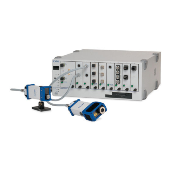
High Performance Power Meter is a module available in different models. It is used with the OHS-1700 Optical Head. Main Features The IQS-1700 High Performance Power Meter is offered with the followingone-, two-, or four-channel models. The OHS-1700 Optical Head is offered in Ultra-High Power option (up to 37 dBm). - Page 10 Introducing the IQS-1700 High Performance Power Meter Main Features Models With Optical Head Connectors IQS-1710 IQS-1720 IQS-1740 Optical head connector LED push IQS-1700 button 1 CH Power Meter IQS-1700 IQS-1700 4-CH Power Meter Retaining 2-CH Power Meter screw knob It features a high sampling rate and fast stabilization, and comes in one-, two- or four-channel options (each detector is independent).
- Page 11 The graphical display mode shows all channels on a real-time graph, which you can analyze afterwards. The IQS-1700 High Performance Power Meter supports local control (via the IQS Manager software) and remote control (through GPIB, RS-232, or Ethernet TCP/IP using SCPI commands or the provided LabVIEW drivers).
-
Page 12: Typical Applications
Introducing the IQS-1700 High Performance Power Meter Typical Applications Typical Applications Your power meter is suitable for numerous applications, including the following: Transceiver testing Amplifier characterization PDL measurements Network monitoring Passive component characterization IQS-1700... -
Page 13: Conventions
Introducing the IQS-1700 High Performance Power Meter Conventions Conventions Before using the product described in this guide, you should understand the following conventions: ARNING Indicates a potentially hazardous situation which, if not avoided, could result in death or serious injury. Do not proceed unless you understand and meet the required conditions. -
Page 15: Safety Information
Safety Information Your power meter does not contain laser components in itself. However, you will be using it with light sources. ARNING Do not install or terminate fibers while a light source is active. Never look directly into a live fiber and ensure that your eyes are protected at all times. -
Page 17: Getting Started With Your High Performance Power Meter
Never insert or remove a module while the controller unit and its expansion units are turned on. This will result in immediate and irreparable damage to both the module and unit. AUTION To avoid damaging your unit, use it only with modules approved by EXFO. High Performance Power Meter... - Page 18 2b. Gently pull the top of the protective cover downwards, to remove it from the unit grooves. Protective cover Retaining screw knob 3. Position the module so that its front panel is facing you and the top and bottom protruding edges are to your right. IQS-1700...
- Page 19 Getting Started with Your High Performance Power Meter Inserting and Removing Test Modules 4. Insert the protruding edges of the module into the grooves of the unit’s module slot. Protruding edges (right side of module) Retaining screw knob Retaining screw 5.
- Page 20 Note: You can insert IQ modules into your controller or expansion unit; the IQS Manager software will recognize them. However, the IQS-1700 locking mechanism (retaining screw) will not work for IQ modules. To remove a module from your controller or expansion unit: 1.
- Page 21 Getting Started with Your High Performance Power Meter Inserting and Removing Test Modules Connector Retaining screw knob AUTION Pulling out a module by a connector could seriously damage both the module and connector. Always pull out a module by the retaining screw knob.
-
Page 22: Connecting The Optical Head To The Power Meter
If the optical head is not connected to its channel, you will notice that the display is different and you cannot perform measurements on this channel until you have connected the head properly. Head properly connected Head not connected IQS-1700... -
Page 23: Securing The Optical Head Onto Your Work Surface
Starting the High Performance Power Meter Application Your IQS-1700 High Performance Power Meter module can be configured and controlled from its dedicated IQS Manager application. Note: For details about IQS Manager, refer to the IQS platform user guide. - Page 24 You can also double-click its row. Note: Pressing the LED push button will not activate or turn on the module. Note: To start the corresponding monitor window at the same time, click Start App. & Monitor. The window opens on the Monitors function tab. IQS-1700...
- Page 25 Getting Started with Your High Performance Power Meter Starting the High Performance Power Meter Application The main window (shown below) contains all the commands required to control the High Performance Power Meter: Title bar Data display Parameter definition controls Status bar Note: When using a multichannel power meter with different optical heads, the settings (such as the wavelength list) used by the application are those detected on the highest channel number.
- Page 26 Remote: Module controlled remotely, but local commands can also be used. Lockout: Module controlled remotely only. Module/unit status Current date and time For more information about automating or remotely controlling the IQS-1700 High Performance Power Meter, refer to your platform user guide. IQS-1700...
-
Page 27: Entering Values Using Sliders And Numeric Boxes
Getting Started with Your High Performance Power Meter Entering Values Using Sliders and Numeric Boxes Entering Values Using Sliders and Numeric Boxes Many parameters in IQS Manager and module applications can be set using the following tools. Slider Fine-tuning Numeric box button Navigation buttons Slider: Drag it to the desired value on the scale below. -
Page 28: Exiting The Application
To close the application from the main window: Click in the top right corner of the main window. Click the Exit button located at the bottom of the function bar. To close all currently running applications: From IQS Manager, click Close All Applications. IQS-1700... -
Page 29: Setting Up Your High Performance Power Meter
Setting Up Your High Performance Power Meter You can set the following parameters on your IQS-1700: Channel display Wavelength selection and management Measurement unit selection Display resolution Refresh rate Measurement range Saving and recalling configuration ... -
Page 30: Setting Channel Display
To set the channel display : 1. From the Instrument function tab, click the Display tab to view the available channels. 2. Select the desired channel. The data display immediately reflects your selection and the selected channel indicator will turn light green. IQS-1700... -
Page 31: Selecting A Channel (Multi-Channel Models)
Setting Up Your High Performance Power Meter Selecting a Channel (Multi-Channel Models) Selecting a Channel (Multi-Channel Models) The optical channels on multi-channel models are independent. To select an optical channel: From the Instrument function tab, go to Channel and use the arrow buttons next to the channel number to change it. -
Page 32: Naming Channels
1. Click the Settings function tab. 2. From the Channels tab, select the channel to name by clicking the corresponding button. 3. Type in a self-explanatory name in the Name box. 4. Click Apply to confirm your new setting. IQS-1700... -
Page 33: Selecting The Wavelength
Setting Up Your High Performance Power Meter Selecting the Wavelength Selecting the Wavelength When taking accurate measurements, your power meter must be set to the correct wavelength to compensate for the photodetector responsivity at the incident wavelength. Ideally, the power meter’s wavelength should be set as close as possible to that of the optical source being used. -
Page 34: Managing Wavelength Lists
Managing Wavelength Lists Managing Wavelength Lists The wavelengths you want to use with your IQS-1700 and OHS-1700 must be entered in the Wavelength list. Please refer to the Certificate of Compliance supplied with your power meter for information on the wavelength range. -
Page 35: Selecting The Measurement Unit
Setting Up Your High Performance Power Meter Selecting the Measurement Unit To delete a wavelength from the list: 1. From the Settings function tab, click the List tab. 2. From, the Wavelength list, select the wavelength to be deleted. 3. Click to confirm the operation. -
Page 36: Setting The Display Resolution
1. Click the Settings function tab, then click the Channels tab. If necessary, select the channel for which you want to set the display resolution. 2. Use the arrow buttons to select the value in the Display Res. list. IQS-1700... - Page 37 Setting Up Your High Performance Power Meter Setting the Display Resolution If you have previously selected watts as units, the Display Res. list will be grayed out (as illustrated above). 3. Click Apply to confirm your new setting. Note: You can also use the All Channels button to modify all channels at once. If other values were set previously, but are different from those you are currently setting, any value you change will turn red to indicate that it is different.
-
Page 38: Setting The Refresh Rate
2. Use the arrow buttons to select the refresh rate you want to use. Note: The refresh rate can be faster or slower than the sampling rate; however, only a refresh rate slower than the sampling rate will have an effect. IQS-1700... -
Page 39: Setting The Measurement Range
Setting Up Your High Performance Power Meter Setting the Measurement Range Setting the Measurement Range The measurement range and gain scale applied to the power detector can be manually selected to prevent the automatic scale adjustment performed by the instrument. A manual adjustment of the dynamic gain scale will lock the measurement range to a specific level. - Page 40 3. Use the arrow buttons next to the Range list to select the range you want to use. Note: Select Manual range for an acquisition when the input signal has unstable or modulated variations. This prevents ! ! ! ! ! ! ! from appearing on the display when changing gain scales often. IQS-1700...
- Page 41 Setting Up Your High Performance Power Meter Setting the Measurement Range 4. Use the arrow buttons next to the Scale list and highlight the scale you wish to use. 5. Click Apply to confirm your new setting. Note: You can also use the All Channels button to modify all channels identically. If other values were set previously, but are different from those you are currently setting, any value you change will turn red to indicate that it is different.
-
Page 42: Saving And Recalling Configurations
Setting Up Your High Performance Power Meter Saving and Recalling Configurations Saving and Recalling Configurations Once you have set the IQS-1700 High Performance Power Meter parameters, you can save your custom configuration and recall it at any time. You can also recall the factory-defined settings. - Page 43 Setting Up Your High Performance Power Meter Saving and Recalling Configurations To recall a configuration: 1. Select the Configuration function tab. 2. Click Open. 3. Select the configuration file you wish to recall and confirm your action. You are returned to the application and the new parameters are set. To revert to factory settings: 1.
-
Page 45: Preparing Your High Performance Power Meter For A Test
To ensure maximum power and to avoid erroneous readings: Always inspect fiber ends and make sure that they are clean as explained below before inserting them into the port. EXFO is not responsible for damage or errors caused by bad fiber cleaning or handling. - Page 46 EXFO uses good quality connectors in compliance with EIA-455-21A standards. To keep connectors clean and in good condition, EXFO strongly recommends inspecting them with a fiber inspection probe before connecting them. Failure to do so will result in permanent damage to the connectors and degradation in measurements.
-
Page 47: Nulling Offsets
Preparing Your High Performance Power Meter for a Test Nulling Offsets Nulling Offsets Temperature and humidity variations affect the performance of electronic circuits and optical detectors, which can offset measurement results. To compensate for this offset, the unit is equipped with an offset nulling function. - Page 48 A red message appears beneath the power value of the channel for which you are performing a nulling. If you are using a multichannel power meter, you will notice that the other channels will stop reading power while nulling is in progress. IQS-1700...
- Page 49 Preparing Your High Performance Power Meter for a Test Nulling Offsets To perform an offset nulling on all channels (two- and four-channel power meters): 1. Install the protective caps over all of the detector ports. 2. Under Nulling, click the All Channels button. Offset nulling values are applied to the channel until a new nulling is performed.
- Page 50 Preparing Your High Performance Power Meter for a Test Nulling Offsets 3. Click OK to perform the offset nulling, or Cancel to exit. A red message appears beneath the power value of the channel for which you are performing a nulling. IQS-1700...
-
Page 51: Measuring Power
Measuring Power Power measurements can be displayed in two ways: absolute relative It is also possible to use a correction factor at specific wavelengths and to add an offset value to your power measurement. Displaying Absolute Power When in absolute power, measured values are displayed in either dBm or W units (pW, nW, W, mW...) and the displayed value represents the absolute optical power reaching the detector within specified uncertainty. - Page 52 6. Return to the Instrument function tab and click Absolute to activate the mode. An absolute power measurement in negative W units indicates that the nulling of the offset was improperly done. If this happens, repeat the offset nulling operation (see Nulling Offsets on page 39). IQS-1700...
-
Page 53: Measuring Relative Power
Measuring Power Measuring Relative Power Measuring Relative Power Power measurements can be displayed as a deviation from an absolute reference value. The relative power is particularly useful when performing loss measurements. Relative power is displayed in dB when the reference value is measured in dBm. -
Page 54: Selecting The Reference Value
3. Click Apply to confirm your new setting. 4. From the Instrument function tab, click the Reference button to use your new reference value. IQS-1700... -
Page 55: Editing The Reference List
Measuring Power Editing the Reference List Editing the Reference List The Reference list can be changed to adapt to your testing requirements. To add a reference to the list: 1. From the Settings function tab, select the Lists tab. 2. Under Reference List, enter the name of the new reference value in the Name box. -
Page 56: Measuring Corrected Power
When expressed in dB, the CF can be a positive or negative value. When the currently selected measurement unit is W, the correction factor is expressed in W/W, indicating a multiplication factor for the current wavelength and channel. The CF expressed in W/W will always be a positive value. IQS-1700... - Page 57 Measuring Power Measuring Corrected Power To set a correction factor: 1. From the Settings function tab, select the Channels tab. 2. Select the channel for which you want to set the CF (in the case of a two- or four-channel power meter). 3.
-
Page 58: Using The Offset Function
2. Select the channel for which you want to set the offset if you are using a multichannel power meter. 3. From the Offset list, use the arrow buttons to adjust the value. 4. Click Apply to confirm your new setting. IQS-1700... -
Page 59: Averaging Measurements
Measuring Power Averaging Measurements Averaging Measurements When the averaging function is enabled on the IQS-1700 High Performance Power Meter, the most recent measurement samples, for which you can set the number, are used to compute an unweighted average. This average is displayed as the measured value. - Page 60 Averaging button to activate the list. Average /Averaging lists To toggle between averaged and unaveraged power measurement: 1. If necessary, select the desired channel from the Instrument function tab. 2. Click the Averaging button to activate or deactivate it. IQS-1700...
-
Page 61: Recording Power Signal Variations
Recording Power Signal Variations The Min./Max. function allows you to record the extremes of a varying power signal when performing a continuous acquisition. For example, it could be used to determine the stability of a light source over time or to measure the polarization-dependent loss (PDL) of a passive component when combined with a polarization state controller. - Page 62 These can be stopped at any time by clicking Stop. If the timer is set, power measurements will stop automatically after the specified duration. Note: The remaining duration is indicated under the Start and Stop button. The Reset button will reinitialize the Min./Max. acquisition results in the data display. IQS-1700...
- Page 63 Recording Power Signal Variations The results of the Min./Max. function are continuously updated in the matching lists. When a logarithmic scale is used, the Max.Min. calculation is made to continuously provides the difference between the two extremes. In a linear scale, the Min./Max. ratio is computed to provide valuable information.
-
Page 65: Performing Acquisitions
Performing Acquisitions You can perform your acquisition on one or several channels at the same time (in the case of multichannel power meters). To select which channel will be affected by your acquisition: 1. From the Settings function tab, select the Data Acquisition tab. 2. -
Page 66: Selecting The Sampling Type
10, and select seconds as the unit, an acquisition will be performed once every ten seconds; if you enter a value of 1 and select seconds as the unit, an acquisition will occur every second, etc. IQS-1700... - Page 67 Performing Acquisitions Selecting the Sampling Type To select a sampling type: 1. From the Settings function tab, select the Data Acquisition tab. 2. Select the sampling type by clicking the corresponding button. If you select Continuous, select the rate to use with the arrow buttons. This rate is a divider of the maximum rate (5208 Hz).
- Page 68 Remember to click to confirm your settings. Note: Use a lower sampling rate with averaging set to active (see Averaging Measurements on page 51) for greater repeatability when measuring very low power. IQS-1700...
-
Page 69: Editing The Frequency Divider List
Performing Acquisitions Editing the Frequency Divider List Editing the Frequency Divider List To select the frequency at which your continuous or single acquisition will be performed, use a value which is a divider of the full frequency value, 5208 Hz. The values available to you are listed located in the List tab of the Settings function tab. -
Page 70: Selecting The Acquisition Mode
In each case, measurements are taken at the selected sampling rate and saved to a user-specified data file. The size of the data files created during acquisition is proportional to the sampling rate and duration of the acquisition. Higher sampling rates and longer durations generate larger quantities of data. IQS-1700... - Page 71 Performing Acquisitions Selecting the Acquisition Mode To select the acquisition mode: 1. From the Settings function tab, select the Data Acquisition tab. 2. From Mode, select the desired mode or combination of modes. High Performance Power Meter...
- Page 72 During the acquisition, you will notice the message Acquisition in progress, then Data transfer in progress in the Instrument function tab. If you click Stop before the data transfer is complete, you will lose your acquisition data. IQS-1700...
- Page 73 Performing Acquisitions Selecting the Acquisition Mode Setting Up Delayed Acquisition Delay Delayed acquisition starts at a specified time after you start the process, and continues for the time you have previously specified if you have selected a combination of Timed and Delayed acquisition types. To set a delay for your acquisition: 1.
- Page 74 Acquisition will start when measured power of channel A is lower than measured power of channel B. (multichannel power meters only) Note: The trigger defines the condition for starting data acquisition. Once begun, acquisitions will continue for the specified duration, regardless of the measured power. IQS-1700...
- Page 75 Performing Acquisitions Selecting the Acquisition Mode To set up the power level trigger condition: 1. From Trigger of the Data Acquisition tab, use the arrow buttons next to the Type list to select the desired condition. 2. Select a channel (if applicable) to be taken as A and B Note: The X and Y values are displayed in the currently selected unit.
-
Page 76: Starting The Acquisition
Graph function in the same tab (for more information on the graph acquisition and visualization mode, see Performing and Analyzing Graph Acquisitions on page 75). Note: You cannot activate Graph mode after the acquisition has already been started. IQS-1700... - Page 77 Performing Acquisitions Starting the Acquisition You can also start the acquisition in the Graph tab by clicking the Start button the same way you would in the Control tab. MPORTANT If you change units on one or more channels using Relative or Absolute mode and that you had enabled Graph mode, the Graph and Start buttons might automatically disable themselves if the resulting changes are not compatible with the base unit used in the...
-
Page 78: Consulting Acquired Data
Once you have acquired data, it is possible to view the results in IQS Manager. To view data previously acquired: 1. In IQS Manager, select the Work on Results (Offline) function tab. 2. Click the tab, then click the button corresponding to the application for which you want to see information. IQS-1700... - Page 79 Performing Acquisitions Consulting Acquired Data 3. In the viewer, retrieve the corresponding file using the button. To view the details pertaining to the channels used for the acquisition, select the General tab. High Performance Power Meter...
- Page 80 Performing Acquisitions Consulting Acquired Data To view your acquisition data, select the Data tab. IQS-1700...
- Page 81 Performing Acquisitions Consulting Acquired Data To view the graph corresponding to your acquisition data, select the Graph tab. To move along the time scale, use the arrow buttons. The single arrow buttons will move by increments or decrements representing 10 % of the current trace scale value. The double arrow buttons will move by increments or decrements of the current screen display (for example, the 10 to 40 seconds display would become 40 to 70 seconds in the figure...
- Page 82 Only the first part of your acquisition file will be displayed in the viewer; to see complete results, you must export the file and view it in a word processing program. To exit the window and return to IQS Manager, click Exit. IQS-1700...
-
Page 83: Performing And Analyzing Graph Acquisitions
Performing and Analyzing Graph Acquisitions The Graph mode of your power meter allows you to view your acquisition as it is performed, and analyze it once it has been completed. Setting Up Graph Parameters Before acquiring data, you should set the parameters that will help you achieve a better viewing afterwards. - Page 84 Continuous Scroll: The display will scroll along to the right as the acquisition progresses. Wraparound: Once the acquisition has reached the end of the screen to the right, it will begin on the left again and cover the previous trace. IQS-1700...
- Page 85 Performing and Analyzing Graph Acquisitions Setting Up Graph Parameters To change the base unit of the acquisition (dBm or watts): Use the arrow buttons in the Settings tab to toggle between them. If you set the base unit before performing an acquisition, you will have the choice between W, dBm, dB, and W/W.
-
Page 86: Printing Graph Results
However, you can also clear the graph display manually. To clear the graph display: Click in the Graph Center. Note: Changing items such as the units or display options will also clear the graph display. Ensure that you have set your parameters beforehand. IQS-1700... -
Page 87: Using The Zoom Function
Performing and Analyzing Graph Acquisitions Using the Zoom Function Using the Zoom Function Once you have performed an acquisition, you can use various zooming tools to help you analyze it. To access and use the zoom tools: Click the Zoom Control tab of the Graph Center. allows you to enlarge a precise portion of the trace by dragging a ... - Page 88 You can pan upwards and downwards, as well as to the left and right. Note: You can only pan to the right and left if the time scale length is larger than the portion displayed on the screen. To revert to the original trace size, click in the Graph Center. IQS-1700...
-
Page 89: Displaying And Moving Markers
Performing and Analyzing Graph Acquisitions Displaying and Moving Markers Displaying and Moving Markers Once you have acquired a trace, you can use markers to take precise measurements. To enable the markers: 1. Select the channel you want to use from the Channel pull-down list in the Markers tab. - Page 90 Zoom tab), the markers will still be visible, but you cannot move them. You must return to the Markers tab to do so. You will notice that the difference between the markers (B A) is automatically refreshed on the lower part of the tab as you move the markers. IQS-1700...
-
Page 91: Monitoring Power Meter Modules
10 Monitoring Power Meter Modules When using your IQS-1700 High Performance Power Meter module, either alone or with other modules in a test setup, you can view module data and status using its monitor window in IQS Manager. Using Monitor Windows Monitor windows display basic data about modules. - Page 92 2. In the Monitor column, select the box next to each module you want to monitor. If you want to monitor all the modules in the current unit, click Select All Monitors. If you want to clear your choices, click Deselect All Monitors. IQS-1700...
- Page 93 Monitoring Power Meter Modules Using Monitor Windows 3. Click Start Monitor to apply your selection. IQS Manager will display the selected monitor windows on the Monitors function tab. Note: To start the highlighted module’s corresponding application at the same time, click Start App. & Monitor. The application will appear in a different window.
-
Page 94: Using Quicktools
2. Using the arrow button in the upper left corner, select QuickTools. The corresponding monitor window flashes when QuickTools is activated. Note: If you want to open the actual application for your module rather than QuickTools, click Show Controller. IQS-1700... - Page 95 Monitoring Power Meter Modules Using QuickTools To close QuickTools: Click the Close button located at the top of the window. Click outside the QuickTools window. To close a monitor window: Click the button on the upper left of the monitor window and select Remove Monitor.
-
Page 97: 11 Maintenance
11 Maintenance To help ensure long, trouble-free operation: Always inspect fiber-optic connectors before using them and clean them if necessary. Keep the unit free of dust. Clean the unit casing and front panel with a cloth slightly dampened ... -
Page 98: Cleaning Fixed Connectors
Do not try to disassemble the unit. Doing so would break the connector. ARNING Looking into the optical connector while the light source is active WILL result in permanent eye damage. EXFO strongly recommends to TURN OFF the unit before proceeding with the cleaning procedure. - Page 99 9. Continue to turn as you withdraw the cleaning tip. 10. Repeat steps 7 to 9, but this time with a dry cleaning tip (2.5 mm tip provided by EXFO). Note: Make sure you don’t touch the soft end of the cleaning tip and verify the cleanliness of the cotton tip.
-
Page 100: Cleaning Detector Ports
4. While applying light pressure (to avoid breaking the detector window), gently rotate the cleaning tip on the detector window. 5. Repeat step 4 with a dry cleaning tip or blow dry with compressed air. 6. Discard the cleaning tips after one use. IQS-1700... -
Page 101: Recalibrating The Unit
Under normal use, the recommended interval for your IQS-1700 High Performance Power Meter is: one year. For newly delivered units, EXFO has determined that the storage of this product for up to six months between calibration and shipment does not affect its performance (EXFO Policy PL-03). -
Page 102: Recycling And Disposal (Applies To European Union Only)
To ensure that your unit conforms to the published specifications, calibration may be carried out at an EXFO service center or, depending on the product, at one of EXFO’s certified service centers. Calibrations at EXFO are performed using standards traceable to national metrology institutes. -
Page 103: 12 Troubleshooting
System units, then remove and reinsert the module. Unit has locked up. Reboot the Intelligent Test System. LED is burnt out. Call EXFO. Pressing LED push Computer has locked Reboot the Intelligent Test button does not System. open the module application’s main... - Page 104 The offset nulling is Perform an offset nulling with incorrect. protective cap installed. The optical source is Wait for source to stabilize (at unstable. least 60 minutes). The correction factor Reset the correction factor to is incorrect. 0.000 dB or 1.000 W/W. IQS-1700...
-
Page 105: Viewing Online Documentation
Troubleshooting Viewing Online Documentation Viewing Online Documentation An online version of the IQS-1700 High Performance Power Meter user guide is available at all times from the application. To access the online user guide: Click Help in the function bar. High Performance Power Meter... -
Page 106: Contacting The Technical Support Group
Contacting the Technical Support Group To obtain after-sales service or technical support for this product, contact EXFO at one of the following numbers. The Technical Support Group is available to take your calls from Monday to Friday, 8:00 a.m. to 7:00 p.m. - Page 107 Select the Technical Support tab to view phone numbers and active Internet links to EXFO’s Technical Support Group. Use these links to send an information request by e-mail or to access EXFO’s web site. Select the Module Information tab to view the module identification, ...
-
Page 108: Transportation
Pack the unit in its original packing material when shipping. Avoid high humidity or large temperature fluctuations. Keep the unit out of direct sunlight. Avoid unnecessary shocks and vibrations. IQS-1700... -
Page 109: 13 Warranty
SPECIAL, INCIDENTAL, OR CONSEQUENTIAL DAMAGES. Liability EXFO shall not be liable for damages resulting from the use of the product, nor shall be responsible for any failure in the performance of other items to which the product is connected or the operation of any system of which the product may be a part. -
Page 110: Exclusions
Warranty Exclusions Exclusions EXFO reserves the right to make changes in the design or construction of any of its products at any time without incurring obligation to make any changes whatsoever on units purchased. Accessories, including but not limited to fuses, pilot lamps, batteries and universal interfaces (EUI) used with EXFO products are not covered by this warranty. -
Page 111: Service And Repairs
5. Return the equipment, prepaid, to the address given to you by support personnel. Be sure to write the RMA number on the shipping slip. EXFO will refuse and return any package that does not bear an RMA number. -
Page 112: Exfo Service Centers Worldwide
Warranty EXFO Service Centers Worldwide EXFO Service Centers Worldwide If your product requires servicing, contact your nearest authorized service center. EXFO Headquarters Service Center 400 Godin Avenue 1 866 683-0155 (USA and Canada) Quebec (Quebec) G1M 2K2 Tel.: 1 418 683-5498... -
Page 113: A Technical Specifications
The following technical specifications can change without notice. The information presented in this section is provided as a reference only. To obtain this product’s most recent technical specifications, visit the EXFO Web site at www.exfo.com. SPECIFICATIONS (IQS/OHS-1700 SERIES) Optical heads must be operated with the IQS-1710/1720/1740 High-Performance Interface Module. -
Page 115: B Scpi Command Reference
SCPI Command Reference This appendix presents detailed information on the commands and queries supplied with your IQS-1700 High Performance Power Meter. MPORTANT Since the IQS controllers and expansion units can house many instruments, you must explicitly specify which instrument you want to remotely control. - Page 116 MMEMory[1..n] ACQuisition <StartStop>,CONT|NCONt ACQuisition? ACQuisition DURation <TimeHour>,<TimeMinute>,<Tim eSecond> DURation? DURation MMAXimum <TimeSecond> MMAXimum? MMAXimum STATe <StateDurMinMax> STATe? FNAMe FNAMe? READ[1..n] [SCALar] POWer SENSe[1..n] AVERage [STATe] <AverageState> [STATe]? COUNt <AverageCount>|MAXimum|MINi mum|DEFault COUNt? [MINimum|MAXimum|DEFault] CORRection COLLect ZERO FACTor [MAGNitude] <CorrectionFactor[<wsp>W/W|D B]>|MAXimum|MINimum|DEFault IQS-1700...
- Page 117 SCPI Command Reference Quick Reference Command Tree Command Parameter(s) [MAGNitude]? [MINimum|MAXimum|DEFault] OFFSet [MAGNitude] <CorrectionOffset[<wsp>W/W|DB ]>|MAXimum|MINimum|DEFault [MAGNitude]? [MINimum|MAXimum|DEFault] FREQuency CONTinuous <ContinuousRate[<wsp>HZ]> CONTinuous? CONTinuous CATalog? NCONtinuous <SingleRate[<wsp>HZ]> NCONtinuous? NCONtinuous CATalog? POWer [DC] RANGe AUTO <AutoRangeState> AUTO? SCALe <Scale> SCALe? SCALe LIST? REFerence <Reference[<wsp>W|DBM]>|MA Ximum|MINimum|DEFault REFerence?
- Page 118 SCPI Command Reference Quick Reference Command Tree Command Parameter(s) WAVelength? [MINimum|MAXimum|DEFault] SLINstrument CATalog? CATalog FULL? SNUMber? STATus? STATus OPERation BIT[1..n] CONDition? TRACe[1..n] [DATA]? TRC1|TRC2|TRC3|TRC4 MAX? TRC1|TRC2|TRC3|TRC4 MIN? TRC1|TRC2|TRC3|TRC4 POINts TRC1|TRC2|TRC3|TRC4[,<Number Point>] POINts? TRC1|TRC2|TRC3|TRC4 UNIT[1..n] POWer DB|DBM|W|W/W|WATT|WATT/W POWer? IQS-1700...
-
Page 119: Product-Specific Commands-Description
SCPI Command Reference Product-Specific Commands—Description Product-Specific Commands—Description :ABORt[1..n] Description This command is used to stop the acquisition currently in progress. On *RST, the equivalent of an ABORt command is performed on any acquisition in progress. Syntax :ABORt[1..n] Parameter(s) None Example(s) INIT:AUTO 1, CONT ABOR See Also... - Page 120 Parameter(s) None Response Syntax <PowerMeasurement> Response(s) PowerMeasurement: The response data syntax for <PowerMeasurement> is defined as a <NR3 NUMERIC RESPONSE DATA> element. It is the stored value on the specified channel. Example(s) READ:POW:DC? FETC1:POW:DC? See Also MEASure:SCALar:POWer:MAX? MEASure:SCALar:POWer:MIN? READ:SCALar:POWer:DC? IQS-1700...
- Page 121 SCPI Command Reference Product-Specific Commands—Description :FORMat[1..n][:DATA] Description This command changes the resolution of the power value when dB or dBm is selected for the specified channel. Syntax :FORMat[1..n][:DATA]<wsp><FormatData> Parameter(s) FormatData: The program data syntax for <FormatData> is defined as a <DECIMAL NUMERIC PROGRAM DATA>...
- Page 122 Syntax :FORMat[1..n][:DATA]? Parameter(s) None Response Syntax <FormatData> Response(s) FormatData: The response data syntax for <FormatData> is defined as a <NR3 NUMERIC RESPONSE DATA> element. This query returns the data format. Example(s) FORM:DATA? See Also FORMat[:DATA] IQS-1700...
- Page 123 SCPI Command Reference Product-Specific Commands—Description :INITiate[1..n]:AUTO Description This command starts or stops an acquisition using the number of points set with the TRAC:POIN command, and the sampling rate set with the SENS:FREQ[:CONT] or SENS:FREQ:NCON commands. At *RST, all acquisitions are stopped. Syntax :INITiate[1..n]:AUTO<wsp><StartStop>,CONT| NCONt...
- Page 124 Product-Specific Commands—Description :INITiate[1..n]:AUTO This parameter allows to set the acquisition mode: CONT set Continuous acquisition. NCON set Single acquisition. Example(s) TRAC:POIN TRC1, 5 INIT:AUTO 1, CONT INIT:AUTO 0, CONT INIT:AUTO 1, NCON See Also ABORt INITiate:AUTO? INITiate:EXTRema MMEMory:ACQuisition TRACe:POINt IQS-1700...
- Page 125 SCPI Command Reference Product-Specific Commands—Description :INITiate[1..n]:AUTO? Description This query returns a value indicating whether a programmed (or "Autostop") acquisition is in progress. Syntax :INITiate[1..n]:AUTO? Parameter(s) None Response Syntax <AcqOnOff> Response(s) AcqOnOff: The response data syntax for <AcqOnOff> is defined as a <NR1 NUMERIC RESPONSE DATA> element.
- Page 126 1 and OFF corresponds to 0. This parameter allows to change the Min./Max. measurement status: 0 - Stops the Min./Max. measurements. 1 - Starts the Min./Max. measurements. Example(s) INIT:EXTR ON See Also ABORt INITiate:AUTO INITiate:AUTO? INITiate:EXTRema? MMEMory:ACQuisition MMEMory:ACQuisition? TRACe:POINt IQS-1700...
- Page 127 SCPI Command Reference Product-Specific Commands—Description :INITiate[1..n]:EXTRema? Description This query returns a value indicating whether Min./Max. power measurements are in progress in Continuous acquisition mode. Syntax :INITiate[1..n]:EXTRema? Parameter(s) None Response Syntax <ExtremaOnOFF> Response(s) ExtremaOnOFF: The response data syntax for <ExtremaOnOFF> is defined as a <NR1 NUMERIC RESPONSE DATA>...
- Page 128 To change the resolution of the displayed power value in dB or dBm, use the FORM[:DATA] command. To know the current measurement unit, use the UNIT:POWer? query. Example(s) INIT:EXTR ON MEAS:POW:MAX? See Also INITiate:EXTRema MEASure:SCALare:POWer:MIN? IQS-1700...
- Page 129 SCPI Command Reference Product-Specific Commands—Description :MEASure[1..n][:SCALar]:POWer: MINimum? Description This query returns the minimum power measurement value recorded for a channel in Continuous acquisition mode. Syntax :MEASure[1..n][:SCALar]:POWer:MINimum? Parameter(s) None Response Syntax <MinPower> Response(s) MinPower: The response data syntax for <MinPower> is defined as a <NR3 NUMERIC RESPONSE DATA>...
- Page 130 0 or OFF - Stops the acquisition. 1 or ON - Starts the acquisition. AcqType: The program data syntax for the second parameter is defined as a <CHARACTER PROGRAM DATA> element. The allowed <CHARACTER PROGRAM DATA> elements for this parameter are: CONT|NCONt. IQS-1700...
- Page 131 SCPI Command Reference Product-Specific Commands—Description :MMEMory[1..n]:ACQuisition The acquisition state can be modified with: CONT -sets the Continuous acquisition rate. NCON -sets the Single acquisition rate. Example(s) MMEM:ACQ 1, CONT MMEM:ACQ? MMEM:ACQ 0, CONT MMEM:ACQ 1, NCON MMEM:ACQ 0, NCON See Also MMEMory:ACQuisition? MMEMory:ACQuisition:DURation MMEMory:ACQuisition:DURation?
- Page 132 <NR1 NUMERIC RESPONSE DATA> element. This query returns the current memory acquisition state: 0 - Memory acquisition is off. 1 - Memory acquisition is on. Example(s) MMEM:ACQ 1, CONT MMEM:ACQ? MMEM:ACQ 0, CONT MMEM:ACQ? See Also MMEMory:ACQuisition MMEMory:ACQuisition:DURation MMEMory:ACQuisition:DURation? ABORt INITiate:AUTO? INITiate:EXTRema IQS-1700...
- Page 133 SCPI Command Reference Product-Specific Commands—Description :MMEMory[1..n]:ACQuisition:DURation Description This command is used to set the duration of an acquisition. Syntax :MMEMory[1..n]:ACQuisition:DURation<wsp>< TimeHour>,<TimeMinute>,<TimeSecond> Parameter(s) TimeHour: The program data syntax for <TimeHour> is defined as a <DECIMAL NUMERIC PROGRAM DATA> element. Used to set the duration of acquisition in hours. TimeMinute: ...
- Page 134 The response data syntax for <AcqTime> is defined as a <DEFINITE LENGTH ARBITRARY BLOCK RESPONSE DATA> element. This query returns the duration for the acquisition in hour, minute, second format. Example(s) MMEM:ACQ:DUR? See Also MMEMory:ACQuisition:DURation MMEMory:ACQuisition MMEMory:ACQuisition:DURation:MMAXimum INITiate:AUTO INITiate:EXTRema IQS-1700...
- Page 135 SCPI Command Reference Product-Specific Commands—Description :MMEMory[1..n]:ACQuisition:DURation: MMAXimum Description This command is used to set the duration of the Min. Max. acquisition. Syntax :MMEMory[1..n]:ACQuisition:DURation:MMAXim um<wsp><TimeSecond> Parameter(s) TimeSecond: The program data syntax for <TimeSecond> is defined as a <DECIMAL NUMERIC PROGRAM DATA> element. Changes the Min.
- Page 136 <AcqMinMaxTime> Response(s) AcqMinMaxTime: The response data syntax for <AcqMinMaxTime> is defined as a <NR1 NUMERIC RESPONSE DATA> element. This query returns the Min. Max. acquisition duration in seconds. Example(s) MMEM:ACQ:DUR:MMAX? See Also MMEMory:ACQuisition:DURation:MMAXimum MMEMory:ACQuisition:DURation:MMAXimum:ST MMEMory:ACQuisition:DURation MMEMory:ACQuisition INITiate:AUTO INITiate:CONTinuous INITiate:EXTRema IQS-1700...
- Page 137 SCPI Command Reference Product-Specific Commands—Description :MMEMory[1..n]:ACQuisition:DURation: MMAXimum:STATe Description This command is used to set the timer state of the Min. Max. acquisition. Syntax :MMEMory[1..n]:ACQuisition:DURation:MMAXim um:STATe<wsp><StateDurMinMax> Parameter(s) StateDurMinMax: The program data syntax for <StateDurMinMax> is defined as a <Boolean Program Data> element.
- Page 138 The response data syntax for <AcqMinMaxState> is defined as a <NR1 NUMERIC RESPONSE DATA> element. This query returns the timer state of Min. Max. acquisition. 0 -Timer is disabled 1 -Timer is enabled Example(s) MMEM:ACQ:DUR:MMAX:STAT? See Also MMEMory:ACQuisition:DURation:MMAXimum MMEMory:ACQuisition:DURation:MMAXimum:ST MMEMory:ACQuisition:DURation MMEMory:ACQuisition INITiate:AUTO INITiate:EXTRema IQS-1700...
- Page 139 SCPI Command Reference Product-Specific Commands—Description :MMEMory[1..n]:FNAMe Description This command is used to set the acquisition file's name and storage location. Syntax :MMEMory[1..n]:FNAMe<wsp><FileName> Parameter(s) FileName: The program data syntax for <FileName> is defined as a <STRING PROGRAM DATA> element. Changes the file name and storage location. Example: PmACQ.tra or D:IQS ManagerUser FilesIqs1x00PmACQ.tra...
- Page 140 None Response Syntax <FileName> Response(s) FileName: The response data syntax for <FileName> is defined as a <STRING RESPONSE DATA> element. This query returns the files name and storage location. Response format: D:IQS ManagerUser FilesIqs1x00PmACQ.tra Example(s) MMEM:FNAM? See Also MMEMory:NAMe IQS-1700...
- Page 141 SCPI Command Reference Product-Specific Commands—Description :READ[1..n][:SCALar]:POWer:DC? Description With this query, a measurement value is stored and returned. To read a specific channel, enter the channel number as a suffix of the READ keyword. The maximum channel is device-dependent. Channel 1 is always used by default. Syntax :READ[1..n][:SCALar]:POWer:DC? Parameter(s)
- Page 142 SCPI Command Reference Product-Specific Commands—Description :READ[1..n][:SCALar]:POWer:DC? Example(s) READ:SCAL:POW:DC? Returns -1.254000E+001 READ:SCAL:POW:DC? Returns 9221120237577961472 (UNDERRANGE) READ:SCAL:POW:DC? Returns 9221120238114832384 (OVERRANGE) READ:SCAL:POW:DC? Returns 9221120238651703296 (INVALID) READ:SCAL:POW:DC? Returns 9221120239188574208 (INACTIVE) See Also FETCh:SCALar:POWer:DC? MEASure:SCALar:POWer:MAX? MEASure:SCALar:POWer:MIN? IQS-1700...
- Page 143 SCPI Command Reference Product-Specific Commands—Description :SENSe[1..n]:AVERage[:STATe] Description This command turns the averaging ON or OFF On *RST, this value is set to OFF. Syntax :SENSe[1..n]:AVERage[:STATe]<wsp><Average State> Parameter(s) AverageState: The program data syntax for <AverageState> is defined as a <Boolean Program Data> element. The <AverageState>...
- Page 144 None Response Syntax <AverageState> Response(s) AverageState: The response data syntax for <AverageState> is defined as a <NR1 NUMERIC RESPONSE DATA> element. State of averaging. 0 -Averaging is disabled 1 -Averaging is enabled Example(s) SENS:AVER:STAT? See Also SENSe:AVERage:STATe SENSe:AVERage:COUNt SENSe:AVERage:COUNt? IQS-1700...
- Page 145 SCPI Command Reference Product-Specific Commands—Description :SENSe[1..n]:AVERage:COUNt Description Sets the number of measurements used to calculate the final measurement's average on the specified channel. At *RST, this value is 2. Syntax :SENSe[1..n]:AVERage:COUNt<wsp><AverageC ount>|MAXimum|MINimum|DEFault Parameter(s) AverageCount: The program data syntax for <AverageCount> is defined as a <numeric_value>...
- Page 146 DATA> elements for this parameter are: MINimum|MAXimum|DEFault. MINimum is used to retrieve the instrument's smallest supported value. MAXimum is used to retrieve the instrument's greatest supported value. DEFault is used to retrieve the instrument's default value. Response Syntax <AverageCount> IQS-1700...
- Page 147 SCPI Command Reference Product-Specific Commands—Description :SENSe[1..n]:AVERage:COUNt? Response(s) AverageCount: The response data syntax for <AverageCount> is defined as a <NR1 NUMERIC RESPONSE DATA> element. This query returns the number of measurements used to perform an averaged measurement. Example(s) SENS:AVER:COUN? See Also SENSe:AVERage:COUNt SENSe:AVERage:[STATe] SENSe:AVERage:[STATe]?
- Page 148 SENS1:CORR:COLL:ZERO Notes This command is not executed if a data acquisition is in progress. In that case, the "acquisition in progress" message will be returned. This command will take at least 30 seconds to complete. See Also SENSe:CORRection:COLLect:ZERO:ALL ABORt IQS-1700...
- Page 149 SCPI Command Reference Product-Specific Commands—Description :SENSe[1..n]:CORRection:COLLect: ZERO:ALL Description This command performs an offset nulling measurement on all channels. Syntax :SENSe[1..n]:CORRection:COLLect:ZERO:ALL Parameter(s) None Example(s) SENS:CORR:COLL:ZERO:ALL Notes This command is not executed if a data acquisition is in progress. In that case, the "acquisition in progress"...
- Page 150 DEFault allows the instrument to select a value for the <CorrectionFactor> parameter. The <numeric _value> parameter is a correction factor using W/W as units. If an invalid parameter is entered, the Parameter out of range message will be returned. IQS-1700...
- Page 151 SCPI Command Reference Product-Specific Commands—Description :SENSe[1..n]:CORRection:FACTor [:MAGNitude] Example(s) SENS:CORR:FACT:MAGN 2 Notes The correction factor expressed in W/W indicates the ratio between the power received (in W) and the reference (in W) for the current wavelength and channel. See Also SENSe:CORRection:FACTor:[MAGNitude]? SENSe:CORRection:OFFSet:[MAGNitude] SENSe:CORRection:OFFSet:[MAGNitude]? High Performance Power Meter...
- Page 152 DATA> elements for this parameter are: MINimum|MAXimum|DEFault. MINimum is used to retrieve the instrument's smallest supported value. MAXimum is used to retrieve the instrument's greatest supported value. DEFault is used to retrieve the instrument's default value. Response Syntax <CorrectionFactor> IQS-1700...
- Page 153 SCPI Command Reference Product-Specific Commands—Description :SENSe[1..n]:CORRection:FACTor [:MAGNitude]? Response(s) CorrectionFactor: The response data syntax for <CorrectionFactor> is defined as a <NR3 NUMERIC RESPONSE DATA> element. The correction factor for the current wavelength and channel is expressed in W/W. If a token is used, it will return the maximum, minimum or default value as specified.
- Page 154 PROGRAM DATA> elements are: W/W|DB. The <CorrectionOffset> special forms MINimum, MAXimum and DEFault are accepted on input. MINimum allows to set the instrument to the smallest supported value. MAXimum allows to set the instrument to the greatest supported value. IQS-1700...
- Page 155 SCPI Command Reference Product-Specific Commands—Description :SENSe[1..n]:CORRection:OFFSet [:MAGNitude] DEFault allows the instrument to select a value for the <CorrectionOffset> parameter. Sets the offset for the specified channel. Example(s) SENS:CORR:OFFS:MAGN 2.0 See Also SENSe:CORRection:OFFSet:[MAGNitude]? SENSe:CORRection:FACTort:[MAGNitude] SENSe:CORRection:FACTor:[MAGNitude]? High Performance Power Meter...
- Page 156 DATA> elements for this parameter are: MINimum|MAXimum|DEFault. MINimum is used to retrieve the instrument's smallest supported value. MAXimum is used to retrieve the instrument's greatest supported value. DEFault is used to retrieve the instrument's default value. Response Syntax <CorrectionOffset> IQS-1700...
- Page 157 SCPI Command Reference Product-Specific Commands—Description :SENSe[1..n]:CORRection:OFFSet [:MAGNitude]? Response(s) CorrectionOffset: The response data syntax for <CorrectionOffset> is defined as a <NR3 NUMERIC RESPONSE DATA> element. This query returns the offset for the specified channel Example(s) SENS:CORR:OFFS:MAGN? See Also SENSe:CORRection:OFFSet:[MAGNitude] SENSe:CORRection:FACTor:[MAGNitude] SENSe:CORRection:FACTor:[MAGNitude]? High Performance Power Meter...
- Page 158 The <numeric_value> parameter is the Continuous acquisition rate. Example(s) SENS:FREQ:CONT 256 Notes This command is not executed if a data acquisition is in progress. In that case, the "acquisition in progress" message will be returned. See Also SENSe:FREQuency:CONTinuous? SENSe:FREQuency:CONTinuous:CATalog? SENSe:FREQuency:NCONtinuous SENSe:FREQuency:NCONtinuous? SENSe:FREQuency:NCONtinuous:CATalog? IQS-1700...
- Page 159 SCPI Command Reference Product-Specific Commands—Description :SENSe[1..n]:FREQuency:CONTinuous? Description This query returns the current continuous acquisition rate in Hz. Syntax :SENSe[1..n]:FREQuency:CONTinuous? Parameter(s) None Response Syntax <ContinuousRate> Response(s) ContinuousRate: The response data syntax for <ContinuousRate> is defined as a <NR2 NUMERIC RESPONSE DATA> element. This query returns the current continuous acquisition rate.
- Page 160 <ContinuousList> Response(s) ContinuousList: The response data syntax for <ContinuousList> is defined as a <DEFINITE LENGTH ARBITRARY BLOCK RESPONSE DATA> element. This query returns the list of available continuous acquisition rates. Example(s) SENS:FREQ:CONT:CAT? See Also SENSe:FREQuency:CONTinuous SENSe:FREQuency:CONTinuous? SENSe:FREQuency:NCONtinuous SENSe:FREQuency:NCONtinuous? SENSe:FREQuency:NCONtinuous:CATalog? IQS-1700...
- Page 161 SCPI Command Reference Product-Specific Commands—Description :SENSe[1..n]:FREQuency:NCONtinuous Description This command sets the single acquisition rate in Syntax :SENSe[1..n]:FREQuency:NCONtinuous<wsp>< SingleRate[<wsp>HZ]> Parameter(s) SingleRate: The program data syntax for <SingleRate> is defined as a <DECIMAL NUMERIC PROGRAM DATA> element followed by an optional <SUFFIX PROGRAM DATA> element. The allowed <SUFFIX PROGRAM DATA>...
- Page 162 Parameter(s) None Response Syntax <SingleRate> Response(s) SingleRate: The response data syntax for <SingleRate> is defined as a <NR2 NUMERIC RESPONSE DATA> element. This query returns the current Single acquisition rate. Example(s) SENS:FREQ:NCON? See Also SENSe:FREQuency:CONTinuous SENSe:FREQuency:CONTinuous? SENSe:FREQuency:CONTinuous:CATalog? SENSe:FREQuency:NCONtinuous SENSe:FREQuency:NCONtinuous:CATalog? IQS-1700...
- Page 163 SCPI Command Reference Product-Specific Commands—Description :SENSe[1..n]:FREQuency:NCONtinuous: CATalog? Description This query returns the list of available single acquisition rates in Hz. Syntax :SENSe[1..n]:FREQuency:NCONtinuous:CATalog? Parameter(s) None Response Syntax <NonContinuousList> Response(s) NonContinuousList: The response data syntax for <NonContinuousList> is defined as a <DEFINITE LENGTH ARBITRARY BLOCK RESPONSE DATA>...
- Page 164 0 or OFF -Disables the AutoRange 1 or ON -Enables the AutoRange Example(s) SENS:POW:RANG:AUTO 1 Notes The Autorange function can be performed in Continuous acquisition mode only. When Autorange is deactivated, LR1 is activated by default. See Also SENSe:POWer:[DC]:RANGe:AUTO? SENSe:POWer:[DC]:RANGe SENSe:POWer:[DC]:RANGe:SCALe SENSe:POWer:[DC]:RANGe:SCALe? SENSe:POWer:[DC]:RANGe:SCALe:LIST? IQS-1700...
- Page 165 SCPI Command Reference Product-Specific Commands—Description :SENSe[1..n]:POWer[:DC]:RANGe:AUTO? Description This query returns a value indicating whether the automatic power measurement range (Autorange) is enabled or disabled for the specified channel. Syntax :SENSe[1..n]:POWer[:DC]:RANGe:AUTO? Parameter(s) None Response Syntax <Autorange> Response(s) Autorange: The response data syntax for <Autorange> is defined as a <NR1 NUMERIC RESPONSE DATA>...
- Page 166 The program data syntax for <Scale> is defined as a <STRING PROGRAM DATA> element. Sets the scale for the specified channel Auto -Automatic range S1 -Scale 1 S2 - Scale 2 Example(s) SENS:POW:RANG:SCAL "S1" See Also SENSe:POWer:[DC]:RANGe:SCALe? SENSe:POWer:[DC]:RANGe:AUTO SENSe:POWer:[DC]:RANGe:AUTO? SENSe:POWer:[DC]:RANGe:SCALe:LIST? IQS-1700...
- Page 167 SCPI Command Reference Product-Specific Commands—Description :SENSe[1..n]:POWer[:DC]:RANGe: SCALe? Description This query returns the currently selected measurement range. Syntax :SENSe[1..n]:POWer[:DC]:RANGe:SCALe? Parameter(s) None Response Syntax <Range> Response(s) Range: The response data syntax for <Range> is defined as a <STRING RESPONSE DATA> element. Current power range, where: Auto -Automatic range S1 -Scale 1 S2 - Scale 2...
- Page 168 BLOCK RESPONSE DATA> element. This query returns the list of power ranges supported. Each value is of NR2 type and is standardized at 1310nm. Format: S1, PowerMin, PowerMax, … Units: Watt Example(s) SENS:POW:RANG:SCAL:LIST? See Also SENSe:POWer:[DC]:RANGe:AUTO SENSe:POWer:[DC]:RANGe:AUTO? SENSe:POWer:[DC]:RANGe:SCALe SENSe:POWer:[DC]:RANGe:SCALe? IQS-1700...
- Page 169 SCPI Command Reference Product-Specific Commands—Description :SENSe[1..n]:POWer[:DC]:REFerence Description This command sets the reference power on the specified channel in watts. Syntax :SENSe[1..n]:POWer[:DC]:REFerence<wsp><R eference[<wsp>W|DBM]>|MAXimum|MINim um|DEFault Parameter(s) Reference: The program data syntax for <Reference> is defined as a <numeric_value> element followed by an optional <SUFFIX PROGRAM DATA>...
- Page 170 DEFault allows the instrument to select a value for the <Reference> parameter. Sets the reference for the specified channel. MIN, MAX and DEF can also be used as parameters. Example(s) SENS:POW:REF 5 See Also SENSe:POWer:[DC]:REFerence? SENSe:POWer:[DC]:REFerence:ALL SENSe:POWer:[DC]:REFerence:DISPlay SENSe:POWer:[DC]:REFerence:STATe SENSe:POWer:[DC]:REFerence:STATe? IQS-1700...
- Page 171 SCPI Command Reference Product-Specific Commands—Description :SENSe[1..n]:POWer[:DC]:REFerence? Description This query returns the reference power in watts on specified channel. Syntax :SENSe[1..n]:POWer[:DC]:REFerence?[<wsp>M INimum|MAXimum|DEFault] Parameter(s) Parameter 1: The program data syntax for the first parameter is defined as a <CHARACTER PROGRAM DATA> element. The allowed <CHARACTER PROGRAM DATA>...
- Page 172 Product-Specific Commands—Description :SENSe[1..n]:POWer[:DC]:REFerence? Response(s) Reference: The response data syntax for <Reference> is defined as a <NR3 NUMERIC RESPONSE DATA> element. This query returns the reference value for the specified channel. Example(s) SENS:POW:REF? See Also SENSe:POWer:[DC]:REFerence SENSe:POWer:[DC]:REFerence:ALL SENSe:POWer:[DC]:REFerence:DISPlay SENSe:POWer:[DC]:REFerence:STATe SENSe:POWer:[DC]:REFerence:STATe? IQS-1700...
- Page 173 SCPI Command Reference Product-Specific Commands—Description :SENSe[1..n]:POWer[:DC]:REFerence: Description This command performs a new reference measurement and changes the display to show relative power (dB or W/W) for all channels. Syntax :SENSe[1..n]:POWer[:DC]:REFerence:ALL Parameter(s) None Example(s) SENS:POW:REF:ALL SENS:POW:REF? SENS2:POW:REF? Notes This command is not executed if a data acquisition is in progress.
- Page 174 Syntax :SENSe[1..n]:POWer[:DC]:REFerence:DISPlay Parameter(s) None Example(s) SENS:POW:REF:DISP SENS:POW:REF? Notes This command is not executed if a data acquisition is in progress. In that case, the "Acquisition in progress" message will be returned. See Also SENSe:POWer:[DC]:REFerence SENSe:POWer:[DC]:REFerence? SENSe:POWer:[DC]:REFerence:ALL SENSe:POWer:[DC]:REFerence:STATe SENSe:POWer:[DC]:REFerence:STATe? IQS-1700...
- Page 175 SCPI Command Reference Product-Specific Commands—Description :SENSe[1..n]:POWer[:DC]:REFerence: STATe Description This command selects whether absolute (dBm or W) or relative (dB or W/W) power measurements are performed. Syntax :SENSe[1..n]:POWer[:DC]:REFerence:STATe<ws p><ReferenceState> Parameter(s) ReferenceState: The program data syntax for <ReferenceState> is defined as a <Boolean Program Data> element.
- Page 176 The response data syntax for <ReferenceState> is defined as a <CHARACTER RESPONSE DATA> element. Current reference mode, where: 0 - is the absolute mode(dBm or W). 1 - is the relative mode (dB or W/W). Example(s) SENS:POW:REF:STAT? See Also SENSe:POWer:[DC]:REFerence SENSe:POWer:[DC]:REFerence? SENSe:POWer:[DC]:REFerence:ALL SENSe:POWer:[DC]:REFerence:DISPlay SENSe:POWer:[DC]:REFerence:STATe IQS-1700...
- Page 177 SCPI Command Reference Product-Specific Commands—Description :SENSe[1..n]:POWer:WAVelength Description This command selects a new operating wavelength on the specified channel. If no channel was specified, the default value used is Syntax :SENSe[1..n]:POWer:WAVelength<wsp><Wave length>|MAXimum|MINimum|DEFault Parameter(s) Wavelength: The program data syntax for <Wavelength> is defined as a <numeric_value>...
- Page 178 Response Syntax <Wavelength> Response(s) Wavelength: The response data syntax for <Wavelength> is defined as a <NR3 NUMERIC RESPONSE DATA> element. This query returns the current wavelength in meters for the specified channel. Example(s) SENS:POW:WAV? See Also SENSe:POWer:WAVelength IQS-1700...
- Page 179 SCPI Command Reference Product-Specific Commands—Description :SLINstrument:CATalog? Description This query returns a comma-separated list of <STRING RESPONSE DATA>, which contains the names of all channels of the module. If no channels are defined, a single null <STRING RESPONSE DATA> is returned. This is not affected by a *RST command.
- Page 180 <STRING RESPONSE DATA> element. The list of <STRING RESPONSE DATA> contains the names of all channels in the module. The immediately following <NR1 NUMERIC RESPONSE DATA> formatted number is the associated channel number. Example(s) SLIN:CAT:FULL? See Also SLINstrument:CATalog? IQS-1700...
- Page 181 SCPI Command Reference Product-Specific Commands—Description :SNUMber? Description This query returns a value indicating the module's serial number. Syntax :SNUMber? Parameter(s) None Response Syntax <SerialNumber> Response(s) SerialNumber: The response data syntax for <SerialNumber> is defined as a <STRING RESPONSE DATA> element. The <SerialNumber>...
- Page 182 READY, means the module is ready, BUSY, means the module is busy, DISCONNECTED, means the module is disconnected, DEFECTIVE, means the module is defective and UNCONFIGURED, means the module is not configured. Example(s) STAT? Returns READY (Module is ready.) IQS-1700...
- Page 183 SCPI Command Reference Product-Specific Commands—Description :STATus:OPERation:BIT[1..n]: CONDition? Description This query returns the state of a specific bit. For the moment, only bit <8> was developed. This bit is used to return the state of the module. If the bit = 0, the module is ready. If the bit = 1, the module is busy.
- Page 184 TRC4 - acquisition made on the channel 4 Response Syntax <TraceData> Response(s) TraceData: The response data syntax for <TraceData> is defined as a <DEFINITE LENGTH ARBITRARY BLOCK RESPONSE DATA> element. This query returns all power measurements for the specified trace. IQS-1700...
- Page 185 SCPI Command Reference Product-Specific Commands—Description :TRACe[1..n][:DATA]? Each power value represents a point in the trace and is returned in the same unit used to perform the acquisition. The number of values in a trace can be retrieved with the TRACe:POINt query. Example(s) TRAC:POIN TRC1, 10 INIT:AUTO 1, CONT...
- Page 186 The response data syntax for <PointMax> is defined as a <NR3 NUMERIC RESPONSE DATA> element. The response corresponds to the highest value in the specified trace. The maximum trace point is returned in the same unit used to perform the acquisition. IQS-1700...
- Page 187 SCPI Command Reference Product-Specific Commands—Description :TRACe[1..n]:MAX? Example(s) INIT:EXTR 1 INIT:EXTR 0 TRAC:MAX? TRC1 Notes A trace must be acquired prior to using this query. The suffix of TRACe[1..n ] is not useful for this command. See Also TRACe:[DATA]? INITiate:EXTRema TRACe:MIN? TRACe:POINts TRACe:POINts? High Performance Power Meter...
- Page 188 The response data syntax for <PointMin> is defined as a <NR3 NUMERIC RESPONSE DATA> element. The response corresponds to the smallest value in the specified trace. The minimum trace point is returned in the same unit used to perform the acquisition. IQS-1700...
- Page 189 SCPI Command Reference Product-Specific Commands—Description :TRACe[1..n]:MIN? Example(s) INIT:EXTR 1 INIT:EXTR 0 TRAC:MIN? TRC1 Notes A trace must be acquired prior to using this query. The suffix of TRACe[1..n ] is not useful for this command. See Also TRACe:[DATA]? INITiate:EXTRema TRACe:MAX? TRACe:POINts TRACe:POINts? High Performance Power Meter...
- Page 190 The sufix [1..n], appearing after the keyword "TRACe", is not used. Syntax :TRACe[1..n]:POINts<wsp>TRC1|TRC2|TRC3|T RC4[,<NumberPoint>] Parameter(s) Trace: The program data syntax for the first parameter is defined as a <CHARACTER PROGRAM DATA> element. The allowed <CHARACTER PROGRAM DATA> elements for this parameter are: TRC1|TRC2|TRC3|TRC4. IQS-1700...
- Page 191 SCPI Command Reference Product-Specific Commands—Description :TRACe[1..n]:POINts This parameter is used to select the trace to use. Each trace corresponds to a channel: TRC1 - acquisition made on channel 1 TRC2 - acquisition made on the channel 2 TRC3 - acquisition made on the channel 3 TRC4 - acquisition made on the channel 4 NumberPoint: ...
- Page 192 TRC3 - acquisition for channel 3 TRC4 - acquisition for channel 4 Response Syntax <PointsCount> Response(s) PointsCount: The response data syntax for <PointsCount> is defined as a <NR1 NUMERIC RESPONSE DATA> element. Number of points in the specified trace. IQS-1700...
- Page 193 SCPI Command Reference Product-Specific Commands—Description :TRACe[1..n]:POINts? Example(s) TRAC:POIN? TRC1 Notes The suffix of TRACe[1..n ] is not useful for this command. See Also TRACe:[DATA]? TRACe:MAX? TRACe:MIN? TRACe:POINts High Performance Power Meter...
- Page 194 DB|DBM|W|W/W|WATT|WATT/WATT. Set the power unit for the specified channel. Example(s) UNIT:POW DBM Notes This command is not executed if a data acquisition is in progress. In that case, the "Acquisition in progress" message will be returned. See Also UNIT:POWer? IQS-1700...
- Page 195 SCPI Command Reference Product-Specific Commands—Description :UNIT[1..n]:POWer? Description This query returns the current power unit for the specified channel. Syntax :UNIT[1..n]:POWer? Parameter(s) None Response Syntax <PowerUnit> Response(s) PowerUnit: The response data syntax for <PowerUnit> is defined as a <CHARACTER RESPONSE DATA> element.
- Page 197 ......81 save............34 after-sales service ........98 connecting optical head to power meter..14 application connectors, cleaning........90 contacting EXFO support from ....99 consulting data ........... 70 exiting ........... 20 contact information, EXFO ......99 starting, single-module......15 continuous auto-scroll graph.........
- Page 198 ........103 imperial-based screw hole ......15 erasing graph display ........78 inserting a module ........9 EXFO support e-mail ........99 EXFO Web site..........99 exiting application........20 label, identification........98 extremes of power signal ......53 LabVIEW drivers..........
- Page 199 Index measuring absolute power........43 pan .............. 80 corrected power ........48 parameters, graph ........75 power ............ 43 PDF. see online user guide relative power........45 port optical head ......... 14 metric-based screw hole......15 position, module ......... 18 module power insertion ..........
- Page 200 49 measurement unit ......... 27 range ............. 31 vertical zoom zone ........79 wavelength..........25 virtual channel shipping to EXFO ........103 with trigger..........67 showing grid............77 markers..........81 single sampling ........58, 60 slot number..........18...
- Page 201 Index W/W correction factor ......... 48 warranty certification ......... 102 exclusions ..........102 general ..........101 liability..........101 wavelength selection........25 work surface, securing optical head on..15 wraparound graph ........76 zoom horizontal ..........79 original size ........... 80 vertical...........
- Page 202 CHINESE REGULATION ON RESTRICTION OF HAZARDOUS SUBSTANCES NAMES AND CONTENTS OF THE TOXIC OR HAZARDOUS SUBSTANCES OR ELEMENTS CONTAINED IN THIS EXFO PRODUCT EXFO Indicates that this toxic or hazardous substance contained in all of the homogeneous materials for this part is below the limit requirement in SJ/T11363-2006...
- Page 203 MARKING REQUIREMENTS Product Environmental protection use period (years) Logo This E product EXFO Battery If applicable.
- Page 204 Tel.: 1 978 367-5600 · Fax: 1 978 367-5700 EXFO FINLAND Elektroniikkatie 2 FI-90590 Oulu, FINLAND Tel.: +358 (0) 403 010 300 · Fax: +358 (0) 8 564 5203 TOLL-FREE (USA and Canada) 1 800 663-3936 © 2014 EXFO Inc. All rights reserved. Printed in Canada (2014-09) ...
Need help?
Do you have a question about the IQS-1700 and is the answer not in the manual?
Questions and answers