Table of Contents
Advertisement
Advertisement
Table of Contents

Related Manuals for EXFO bv10


Summary of Contents for EXFO bv10
- Page 1 User Guide BV10 Performance Endpoint Unit...
- Page 2 EXFO Inc. (EXFO). Information provided by EXFO is believed to be accurate and reliable. However, no responsibility is assumed by EXFO for its use nor for any infringements of patents or other rights of third parties that may result from its use.
-
Page 3: Certification Information
European Community Declaration of Conformity An electronic version of the declaration of conformity for your product is available on our website at www.exfo.com. Refer to the product’s page on the Web site for details. Laser This product complies with 21 CFR 1040.10 except for deviations pursuant... -
Page 4: Table Of Contents
Configuring BV10 Verifier for BrixWorx Registry ..............23 Configuring a Test .........................24 Verifier Health Information ....................28 6 Introducing the BV10 CLI ................29 Command Line Interface .......................29 Connecting to the BV10 to a Console ...................30 Entering Commands ......................33 CLI Session ..........................37 7 CLI Command Reference ................39 Conventions ..........................39 Command Availability ......................39... - Page 5 12 Warranty ..................... 87 General Information ......................87 Liability ..........................88 Exclusions ..........................89 Certification ..........................89 Service and Repairs .......................90 EXFO Service Centers Worldwide ..................91 A Specifications ..................... 93 General Specifications ......................93 Electrical Interface .......................95 Optical Interface ........................95 B Glossary ...................... 97 Acronym List ........................97 Ethernet Cables .........................102...
-
Page 7: Introducing The Bv10
Carrier Ethernet, and PTN networks. Features Fully integrated in EXFO’s end-to-end mobile backhaul solution for service turn-up, troubleshooting, and performance monitoring. Offers complete network visibility at a third of the cost of traditional ... -
Page 8: Brixworx For Turn Up
BrixWorx for Turn Up does not support active or passive testing. The BV10 Verifier is designed specifically for Ethernet OAM Handling, UDP Echo Responder, TWAMP Light Responder, and Smart Loopback test features. These features are enabled by loading the tests on the Verifier... -
Page 9: Conventions
Introducing the BV10 Conventions Conventions Before using the product described in this guide, you should understand the following conventions: ARNING Indicates a potentially hazardous situation which, if not avoided, could result in death or serious injury. Do not proceed unless you understand and meet the required conditions. -
Page 11: Safety Information
Ensure that you understand and meet the required conditions before using your product. MPORTANT Other safety instructions relevant for your product are located throughout this documentation, depending on the action to perform. Make sure to read them carefully when they apply to your situation. BV10-100 and BV10-1000... -
Page 12: Additional Laser Safety Information
The laser classification is reproduced on the pluggable transceiver or in its documentation. ARNING When the LASER LED is on or flashing, the BV10 is transmitting an optical signal on the SFP transceiver port. BV10... -
Page 13: Installation Instruction Warnings
before inserting or removing SFP transceiver to/from the unit. AUTION For DC version, the BV10 must be installed in Restricted Access Locations. MPORTANT Unauthorized modifications to this equipment shall void the user’s authority to operate this equipment. -
Page 14: Other Safety Symbols On Your Unit
One or more of the following symbols may also appear on your unit. Symbol Meaning Direct current. Alternating current. Plus; positive polarity. – Minus, negative polarity. The unit is equipped with an earth (ground) terminal. The unit is equipped with a protective conductor terminal. BV10... -
Page 15: Getting Started
Getting Started Installing the BV10 in a Rack The BV10 can be mounted in a rack using the rack mount accessory kit (ordered separately). The accessory kit shelf holds up to four BV10. To install the BV10 in a rack: 1. -
Page 16: Connecting The Power
The BV10 is available with either an AC power supply, DC +24 V connector, or DC –48 V connector. As soon as the BV10 is connected to a live power supply, the POWER LED turns on. If the POWER LED does not turn on, there is a power failure at the source or the unit is damaged. - Page 17 You will need to supply a #12 AWG wire. ARNING The BV10 DC version is intended to be grounded. Ensure that the unit is connected to earth ground during normal use. AC unit ground...
- Page 18 2. Connect the other end of the power supply to the DC barrel power connector on the BV10. Connecting the BV10 using a DC Power Source The BV10 DC version is equipped with either +24 V DC or –48 V DC connector. ARNING Powering a BV10 +24 V DC unit with a –48 V power source will...
- Page 19 Negative ( ) supply wire lead on the left Positive (+) supply wire lead on the right 2. Connect the plug to one of the two DC input connectors on the BV10 unit and tighten the screws firmly. BV10-100 and BV10-1000...
- Page 20 The switch must be specified as the disconnecting device for the equipment. 4. To add a redundant DC power source on the BV10, repeat step 1 through step 3. ARNING To avoid serious injuries as well as irreparable damages to your unit, ALWAYS TURN OFF BOTH DISCONNECT DEVICES BEFORE OPENING OR SERVICING THE UNIT.
-
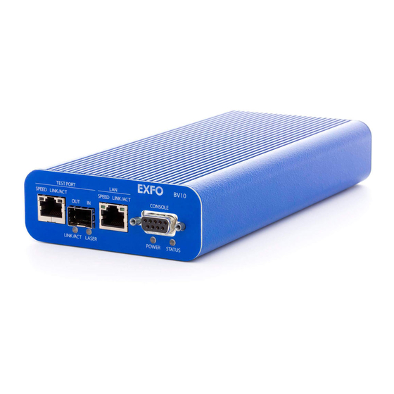
Page 21: Physical Interfaces, Leds, And Buttons
Physical Interfaces, LEDs, and Buttons This section describes all connectors (ports), LEDs, and buttons available on the BV10-100 and BV10-1000 units. BV10 Models BV10-100 CONSOLE TEST BV10-1000 CONSOLE TEST Laser radiation emitted from this port when LASER LED is on. -
Page 22: Port Availability On Bv10
Connecting the TEST Port Interface The BV10-100 provides an electrical 10/100 Mbit/s Ethernet Test interface while the BV10-1000 provides an electrical 10/100/1000 Mbit/s and an optical 1000 Mbit/s SFP laser Ethernet Test interfaces. The two BV10-1000 Test interfaces are mutually exclusive. RJ45 Port Connect the 10/100/1000 Mbit/s electrical interface to be tested to the RJ45 test port. - Page 23 The optical port is a Small Form Factor Pluggable (SFP) slot type with LC connector. Insert an SFP module into the SFP test port slot on the BV10. Refer to Optical Interface on page 95 for more information on supported SFP .
-
Page 24: Connecting The Management Interfaces
LAN port provides remote access to the BV10 Command Line Interface (CLI) using either Telnet or SSH session. To connect remotely to the BV10 using the LAN port, connect both the BV10 LAN port and the remote PC to the same Management network using a standard straight through Ethernet cable with RJ45 connectors. - Page 25 Physical Interfaces, LEDs, and Buttons Connecting the Management Interfaces CONSOLE Port Connecting a PC to the CONSOLE port provides local access to the BV10 using CLI commands. The following figure shows the DB9 (RS-232 DE-9F DCE) pinouts as viewed from the front of the BV10.
-
Page 26: Leds
Physical Interfaces, LEDs, and Buttons LEDs LEDs POWER On (Green) indicates that the BV10 unit is receiving power from an external source. Off indicates that the BV10 unit is not receiving power from the external source or the unit is damaged. -
Page 27: Reset And Default Buttons
Physical Interfaces, LEDs, and Buttons RESET and DEFAULT Buttons RESET and DEFAULT Buttons The RESET and DEFAULT buttons are recessed on the back of the BV10 to avoid accidental use. RESET DEFAULT RESET Button The RESET button is used to reboot the BV10. Press the RESET button once to reboot the BV10. -
Page 29: Managing Bv10 Verifier On Brixworx
BrixWorx registry and describes how to set up tests using the BrixWorx user interface. Note: When the BV10 is used in a BrixWorx environment, you must use BrixWorx GUI rather than CLI prompt to manage the BV10 device. When you change a reflector to run or not through the CLI, this is not updated on the BrixWorx GUI Additional Services page. -
Page 30: Configuring A Test
Refer to the BrixWorx User Guide for more information on how to add the BV10 Verifier to the BrixWorx system. Configuring a Test Only a specific set of BrixWorx tests are supported by the BV10 Verifier. All tests supported on the BV10 Verifier are available through BrixWorx: Ethernet OAM Handling ... - Page 31 Managing BV10 Verifier on BrixWorx Configuring a Test To configure a test on a BV10 Verifier using the BrixWorx Operations Centre: 1. Login to BrixWorx. 2. Select Verifiers. BV10-100 and BV10-1000...
- Page 32 Managing BV10 Verifier on BrixWorx Configuring a Test 3. Click the name of the Verifier on which you want to configure the test. 4. Click the edit button for Additional Services. You can choose to load a specific test or service on this page.
- Page 33 Managing BV10 Verifier on BrixWorx Configuring a Test 5. Enter the time interval at which you want the BV10 Verifier to report the health information. See Verifier Health Information on page 28 for more information. 6. Select Load for the tests that you want to configure on the BV10 Verifier.
-
Page 34: Verifier Health Information
Verifier Health Information Verifier Health Information The BV10 Verifier runs its health status test based on the interval set in the Status field in the Additional Services category of the Verifier’s advanced parameters. It reports results to BrixWorx based on its polling interval. The following figure shows an example of Verifier health information. -
Page 35: Introducing The Bv10 Cli
Command Line Interface The Command Line Interface (CLI) allows to configure and manage the operation of the BV10 by sending commands to the BV10 using either the CONSOLE Port, a Telnet session (LAN or TEST Port), or Secure Shell (SSH) session (LAN or TEST Port). -
Page 36: Connecting To The Bv10 To A Console
CONSOLE port is always available for CLI use. To use the CONSOLE port: 1. Ensure that your PC is connected to the BV10‘s CONSOLE port. Refer to CONSOLE Port on page 19. 2. Use a terminal application to connect with the BV10 through its CONSOLE port. - Page 37 3. Select Telnet or SSH connection type. The use of Telnet server is enabled by default on the BV10. The use of SSH server is disabled by default on the BV10 and must be enabled as well as the password must be defined; refer respectively to console telnet|ssh server enable|disable on page 61 and password set password on page 61;...
- Page 38 3. Select Telnet or SSH connection type. The use of Telnet server is enabled by default on the BV10. The use of SSH server is disabled by default on the BV10 and must be enabled as well as the password must be defined; refer respectively to console telnet|ssh server enable|disable on page 61 and password set password on page 61;...
-
Page 39: Entering Commands
Introducing the BV10 CLI Entering Commands Entering Commands Once you have connected to the BV10, you can enter CLI commands at the command prompt. The CLI command prompt is either BV10-100> , depending on the BV10 model you are communicating with. - Page 40 Introducing the BV10 CLI Entering Commands Completing Commands To submit a CLI command, press the Enter key. The CLI command completion feature lets you type part of a command and use the Tab key to complete the remainder of the command. Consider the following examples.
- Page 41 Introducing the BV10 CLI Entering Commands Command Editing Keys The CLI uses common line editing key sequences, as shown in the following table. Key Sequence Result Enter Executes the command. Backspace Deletes the character to the left of the cursor’s position.
- Page 42 BV10, line editing keys are interpreted by the SSH client and not by the CLI shell on the BV10. It might be required to press Enter after using certain keys, such as Tab and ? for example, to get the result described in the above table.
-
Page 43: Cli Session
Idle Timeout The BV10 has a security feature, called the idle timeout, that logs users out of a CLI session and closes the connection if there has been no activity for a specified period of time. An idle timeout can be set for each type of access (CONSOLE port, Telnet session, or SSH session). -
Page 45: Cli Command Reference
CLI, this is not updated on the BrixWorx GUI Additional Services page. The GUI changes override the changes done using the CLI prompt. Note: Refer to Introducing the BV10 CLI on page 29 for more information on CLI and its features. Conventions The following table lists the conventions used in this chapter to represent command syntax. -
Page 46: Alphabetical List Of Cli Commands
CLI Command Reference Alphabetical List of CLI Commands Alphabetical List of CLI Commands The following table lists the BV10 CLI commands in alphabetical order. Command Page clear statistics console in-band enable|disable console in-band port port_value console telnet|ssh|serial idle-timeout value_in_seconds console telnet|ssh server enable|disable... - Page 47 BV10-100 and BV10-1000...
-
Page 48: Operation Commands
CLI Command Reference Operation Commands Operation Commands Operation commands allow to view and change the operational behavior of the BV10. Operation commands do not change the configuration of the unit. The Operation commands are organized as follows: Subgroup Command Page... - Page 49 Changes password ping Ping IP address reboot Reboots the system show Show statistics, configurations, version, system, server information smart-loopback Configures Smart Loopback mode twamp Configures TWAMP udp-echo Enables/disables UDP echo server Configures local/network/universal registry and port information BV10-100 and BV10-1000...
- Page 50 parameters. If the partial keyword is ambiguous, displays the possible choices. The question mark character is not echoed on the screen. Syntax Examples bv10-100> ? clear help password smart-loopback console interface...
- Page 51 System Commands reboot Description Restarts the BV10. Before restarting the unit, the CLI prompts for confirmation. The RESET button can also be used to reboot the BV10. Refer to RESET Button on page 21 for more information. Syntax reboot Example bv10-100>...
- Page 52 CLI Command Reference Operation Commands show sysinfo Description Displays the following BV10 unit information: Software/firmware versions Hardware model, version, and identification Serial number Manufacturing date Unit Health Status of the test port: LINK DOWN or OK (link up) ...
- Page 53 Loads a software upgrade/downgrade image from TFTP or FTP (using a username and password) server. The BV10 acts as a client. The BV10 can be upgraded or downgraded to the next or previous two versions, preserving the unit’s settings. The unit can be upgraded or downgraded more than two versions;...
- Page 54 (TFTP or FTP) from which the unit is being updated: tftp://192.168.1.1/image_name.img ftp://username:password@192.168.1.1/image_name.img Example bv10-100> load image lan tftp://10.17.1.75/BV-10_4.0SP1.img WARNING: Performing image upgrade. Please DO NOT power down!! Use CTRL-C to abort. Shutting down processes for upgrade...done. Transferring BV-10_4.0SP1.img from 10.17.1.75 using tftp...done(5149757 bytes).
- Page 55 Number of processed Ethernet OAM Loopback messages Number of processed Ethernet OAM Delay Measurement messages Number of processed Ethernet OAM Link Trace messages Syntax show statistics Example bv10-100> show statistics Smart Loopback Control = enabled Smart Loopback Status Link DHCP...
- Page 56 CLI Command Reference Operation Commands clear statistics Description Clears the counter of all statistics. Syntax clear statistics Example bv10-100> clear statistics Clearing statistics BV10...
- Page 57 Auto-negotiation status DHCP status VLAN MDI/MDI-X status Flow control Transceiver type (Test port on BV10-1000 only) Additional information for BV10-1000 optical port: Laser Control SFP vendor manufacturing information (as per SFF-8472): ID, Part Number, Serial Number, Vendor Name, Connector Type (e.g.: LC, MT-RJ...), Speed, Type (for example: SR, IR, LR),...
- Page 58 CLI Command Reference Operation Commands show interface Example bv10-100> show interface all LAN PORT IP_ADDRESS = 10.17.16.32 NETMASK = 255.255.0.0 MAC_ADDRESS = 00:E0:0C:BC:E5:60 GATEWAY = 10.17.1.2 SPEED = 100Mb/s DUPLEX = Full LINK = yes AUTO-NEG = on DHCP = Disabled...
- Page 59 4000 for timeout value_in_ms Example bv10-100> ping 10.10.10.20 lan PING 10.10.10.20 (10.10.10.20) from 10.10.10.180 eth0: 24(52) bytes of data. 32 bytes from 10.10.10.20: icmp_seq=1 ttl=128 time=10.0 ms 32 bytes from 10.10.10.20: icmp_seq=2 ttl=128 time=0.000 ms 32 bytes from 10.10.10.20: icmp_seq=3 ttl=128 time=0.000 ms 32 bytes from 10.10.10.20: icmp_seq=4 ttl=128 time=0.000 ms...
- Page 60 Description Sets the BrixWorx local registry IP address for communication. Syntax server discovery local IP address Example bv10-100> server discovery local 10.192.3.34 server discovery network Description Sets the BrixWorx network registry IP address for communication. Syntax server discovery network IP address Example bv10-100>...
- Page 61 80. Syntax server discovery port IP address Example bv10-100> server discovery port 80 server discovery write Description Changes the IP address or Port number to the new value set by the server discovery local|network|port|universal and saves the setting.
- Page 62 Description Displays the IP address of the currently set local BrixWorx registry. Syntax show server discovery local Example bv10-100> show server discovery local discovery-host = 10.192.3.34 show server discovery network Description Displays the BrixWorx network registry IP address for communication.
- Page 63 CLI Command Reference Operation Commands show server log Description Displays the server log for the local BrixWorx registry. Syntax show server log Example bv10-100> show server log BV10-100 and BV10-1000...
-
Page 64: Configuration Commands
CLI Command Reference Configuration Commands Configuration Commands BV10 Configuration commands allow to view and change the configuration of the BV10. The Configuration commands are organized into the following subgroups: Subgroup Command Page General show config Console password set password password clear... - Page 65 General Command show config Description Displays all BV10 configuration parameters as follows: Console: Console in-band management , Console Password , Console Timeout, Telnet , Telnet Timeout, SSH...
- Page 66 CLI Command Reference Configuration Commands show config Example bv10-100> show config Console CONSOLE_IN_BAND = enabled CONSOLE_PASSWORD = disabled CONSOLE_TIMEOUT TELNETD_ENABLE = enabled TESNETD_TIMEOUT SSHD_ENABLE = disabled SSHD_TIMEOUT Interfaces LAN_ADDRESS = 10.17.16.32 LAN_MASK = 255.255.0.0 LAN_GATEWAY = 10.17.1.2 LAN_AUTO_SPEED = on...
- Page 67 Console Commands password set password Description Defines a password for the BV10. By default, no password is set. The password is case sensitive. When you enter a password, the CLI prompts you to confirm the password by entering it again.
- Page 68 BrixWorx server from the Test port. Syntax console in-band port port_valueh Example bv10-100> console in-band port 300 console telnet|ssh|serial idle-timeout value_in_seconds Description Sets the idle timeout for the Telnet server, SSH server, or serial console communication session. Each connection method can have its own timeout.
- Page 69 Description Turns the laser of the TEST optical interface on or off. This command applies to the BV10-1000 only and is available only when the transceiver type is set to optical. This command cannot be sent through the Test port.
- Page 70 This command cannot be sent through the Test port. Syntax interface test speed 10|100|1000 auto Example bv10-100> interface test speed 100 auto interface test speed 10|100|1000 force Description Forces the electrical TEST port speed (10/100/1000) to the specified value; no auto-negotiation is performed.
- Page 71 This command cannot be sent through the Test port. Syntax interface lan speed 10|100 force Example bv10-100> interface lan speed 100 force interface test speed 1000 auto Description Auto-negotiates the specified optical TEST port speed (1000). This command cannot be sent through the Test port.
- Page 72 This command cannot be sent through the Test port. Syntax interface lan duplex half | full Example bv10-100> interface lan duplex full interface lan flow auto Description Auto-negotiates the flow control for the LAN port to either receive (rx) or none.
- Page 73 | test vlan value | none Example bv10-100> interface lan vlan none interface test vlan priority value Description Sets the VLAN priority of the TEST interface. Syntax interface test vlan priority value Example bv10-100> interface test vlan priority 1 BV10-100 and BV10-1000...
- Page 74 RFC2131. The CLI provides information about the DHCP acquisition status and the lease (expiration time). For more information, refer to show interface on page 51 The BV10 supports IPv4 addressing. The netmask value can be specified in either dotted decimal notation or CIDR format. For example: 192.168.1.1/255.255.255.0...
- Page 75 DHCP, the default gateway is automatically set to DHCP. The gateway can still be configured to none. Syntax interface lan|test gateway dhcp|none Example bv10-100> interface lan gateway 10.17.1.2 BV10-100 and BV10-1000...
- Page 76 Ethernet All Unicast Ethernet UDP/TCP (default) Refer to Smart Loopback Test on page 74 for more information. Syntax smart-loopback mode ethernet-all-unicast|ethernet|ip|udp-tcp Example bv10-100> smart-loopback mode udp-tcp smart-loopback mode udp-tcp bv10-100> smart-loopback mode ethernet smart-loopback mode ethernet BV10...
- Page 77 TWAMP UDP listening port to 7, the following error message is displayed: Command is not allowed - UDP Echo is enabled. Syntax twamp udp-port value Example bv10-100> twamp udp-port 4444 twamp udp-port 4444 udp-echo enable|disable Description Enables or disables the UDP Echo application. UDP Echo is enabled by default.
- Page 78 CLI Command Reference Configuration Commands eth-oam enable|disable Description Globally enables or disables the Ethernet OAM handling application. Ethernet OAM handling is enabled by default. Syntax eth-oam enable | disable Example bv10-100> eth-oam disable eth-oam disabled BV10...
-
Page 79: Test Applications
Smart Loopback supports wire-speed operation with TWAMP, UDP , and OAM handlers. In addition to the test applications listed above, the BV10 responds to ARP and Ping packets targeted to the unit (not wire-speed). The BV10 provides counters for the number of packets processed by each test and each Ethernet OAM message type. -
Page 80: Smart Loopback Test
70 for more information. Modes The Smart Loopback mode limits the address/port swapping to a specific layer. The BV10 supports the following Smart Loopback modes: UDP/TCP (default) – Swap MAC addresses, IP addresses, UDP or TCP ... - Page 81 DHCP Failed Ethernet All Unicast Not Operational Operational Operational Ethernet Not Operational Operational Operational Not Operational Operational Not Operational UDP/TCP Not Operational Operational Not Operational Note: Laser Off produces a Link Down status for the optical transceiver port. BV10-100 and BV10-1000...
-
Page 82: Ping Test
The Ping test returns the following statistics: Number of packets transmitted. Number of packets received. Percentage of packet loss. Round-trip time (rtt) in ms (minimum, average, maximum, and standard deviation values). Refer to ping on page 53 for more information. BV10... -
Page 83: Twamp Light Responder Test
The TWAMP Light Responder test can be enabled (default) or disabled. Refer to twamp enable|disable on page 71 for more information. The UDP Listening port (default is 9495) is specified with the twamp udp-port command. Refer to twamp udp-port value on page 71 for more information. BV10-100 and BV10-1000... -
Page 84: Udp Echo Responder Test
UDP destination port is 7 (UDP Echo, as per RFC862). The UDP Echo Responder test supports wire-speed operation. The UDP Echo Responder test can be enabled (default) or disabled. Refer to udp-echo enable|disable on page 71 for more information. BV10... -
Page 85: Ethernet Oam Handling Test
No VLAN ID checking is done. The Ethernet OAM feature responds with VLAN parameters of the received packet. In addition, no MEG-level discrimination is done, which allows the BV10 to operate in promiscuous mode (the unit operates as a MEP at multiple levels without any MEG-level configuration). - Page 86 OpCode is 47 (DMM). Link Trace The BV10 responds to Ethernet OAM Link Trace messages when all of the following criteria are met: Global Ethernet OAM handling is enabled (default). Destination MAC address is 01-80-C2-00-00-3y, where y is a value ...
-
Page 87: Power Failure Recovery
Power Failure Recovery In the case of a power failure, the BV10 unit: recovers automatically when power is restored. returns to the same state as before the power failure. maintains all configuration parameters such as Test port, Management ... -
Page 89: 10 Maintenance
ARNING The use of controls, adjustments and procedures, namely for operation and maintenance, other than those specified herein may result in hazardous radiation exposure or impair the protection provided by this unit. BV10-100 and BV10-1000... -
Page 90: Cleaning Lc Connectors
SFP manufacturer. Note: Refer to the transceiver manufacturer for more detailed cleaning recommendations and instructions. Recycling and Disposal (Applies to European Union Only) For complete recycling/disposal information as per European Directive WEEE 2012/19/UE, visit the EXFO Web site at www.exfo.com/recycle. BV10... -
Page 91: 11 Troubleshooting
11 Troubleshooting Solving Common Problems Before calling EXFO’s technical support, please read the following common problems that can occur and their respective solution. Problem Possible Cause Solution Optical Laser LED is off and There is a configuration Ensure that the SFP is... -
Page 92: Contacting The Technical Support Group
Contacting the Technical Support Group To obtain after-sales service or technical support for this product, contact EXFO at one of the following numbers. The Technical Support Group is available to take your calls from Monday to Friday, 8:00 a.m. to 7:00 p.m. -
Page 93: 12 Warranty
12 Warranty General Information EXFO Inc. (EXFO) warrants this equipment against defects in material and workmanship for a period of 1 year from the date of original shipment. EXFO also warrants that this equipment will meet applicable specifications under normal use. -
Page 94: Liability
Liability Liability EXFO shall not be liable for damages resulting from the use of the product, nor shall be responsible for any failure in the performance of other items to which the product is connected or the operation of any system of which the product may be a part. -
Page 95: Exclusions
Warranty Exclusions Exclusions EXFO reserves the right to make changes in the design or construction of any of its products at any time without incurring obligation to make any changes whatsoever on units purchased. Accessories, including but not limited to fuses, pilot lamps, batteries and universal interfaces (EUI) used with EXFO products are not covered by this warranty. -
Page 96: Service And Repairs
5. Return the equipment, prepaid, to the address given to you by support personnel. Be sure to write the RMA number on the shipping slip. EXFO will refuse and return any package that does not bear an RMA number. -
Page 97: Exfo Service Centers Worldwide
Crossing), No. 467, support.asia@exfo.com National Highway 107, Xixiang, Bao An District, Shenzhen, China, 518126 To view EXFO's network of partner-operated Certified Service Centers nearest you, please consult EXFO's corporate website for the complete list of service partners: http://www.exfo.com/support/services/instrument-services/ exfo-service-centers. BV10-100 and BV10-1000... -
Page 99: A Specifications
Not rated for measurement categories II, III, or IV. Overvoltage category AC version input power 9 V; 1 A DC –48 V input power –40 - –72 V; 0.2 A DC +24 V input power 20 - 32 V; 0.4 A BV10-100 and BV10-1000... -
Page 100: Specifications
AC/DC adapter must be a Listed/Certified (external direct plug-in SMPSU, Overvoltage (Installation) category II) having reinforced insulation between primary and secondary and suitably rated for the extended BV10 operating environmental conditions (altitude, temperature, and humidity) and with output rating (voltage and current) compatible with above specifications. -
Page 101: Electrical Interface
1270 to 1360 1540 to 1570 Maximum Rx before damage (dBm) Jitter compliance IEEE 802.3 IEEE 802.3 Ethernet classification IEEE 802.3 IEEE 802.3 Laser type VCSEL Eye safety Class 1 Class 1 Class 1 Connector Transceiver type BV10-100 and BV10-1000... -
Page 103: B Glossary
Help Ampere Alternating Current Activity Address Resolution Protocol American Wire Gage bit/s Bit per second CAGE Commerce And Government Entities Clean Dry Air CIDR Classless Inter-Domain Routing Command Line Interface Central Office Direct Current Data Communications Equipment BV10-100 and BV10-1000... - Page 104 Glossary Acronym List Clean Dry Air DHCP Dynamic Host Configuration Protocol Delay Measurement Message Electrostatic Discharge EXFO Universal Interfaces Federal Communications Commission File Transfer Protocol Graphical User Interface ICMP Internet Control Message Protocol Identification International Electrotechnical Commission inches Input Internet Protocol...
- Page 105 Pound Link Trace Message Media Access Control Mbit/s Megabit per second Media Dependant Interface (straight through Ethernet cable) MDIX Media Dependant Interface Crossover (crossover Ethernet cable) ME Group MEG End Point NATO North Atlantic Treaty Organization Nanometer BV10-100 and BV10-1000...
- Page 106 Operation, Administration, and Maintenance OUTput Personal Computer Return Merchandise Authorization Round-trip time Receive Small Form Factor Pluggable Secure Shell Transport Control Protocol TFTP Trivial File Transfer Protocol Type, Length, and Value Time To Live TWAMP Two-Way Active Measurement Protocol Transmit BV10...
- Page 107 Glossary Acronym List User Data Protocol United States of America Unshielded Twisted Pairs Volt VLAN Virtual Local Area Network BV10-100 and BV10-1000...
-
Page 108: Ethernet Cables
1000Base-T connection is 328 feet (100 meters). Straight Through Cable (10/100 Mbit/s) An Unshielded Twisted Pair (UTP) straight through cable is required to connect a 10Base-T/100Base-TX BV10 port to a layer 1 or 2 device (ex: HUB, switch). Crossover Cable (10/100 Mbit/s) ... - Page 109 Glossary Ethernet Cables Straight Through Cable (1000 Mbit/s) Crossover Cable (1000 Mbit/s) BV10-100 and BV10-1000...
-
Page 111: Index
............53 reboot............ 45 server discovery local ......54 BrixWorx server discovery network......54 Configuring a test for BV10 verifier on Brix- server discovery port ......55 Worx ........24 server discovery universal....... 54 Configuring BV10 for BrixWorx Registry 23 server discovery write...... - Page 112 ........... 3 identification label ........86 Safety information......... 5 Idle timeout ..........37 Safety symbols..........8 Installing the BV10 in a rack......9 SC connector cleaner ........84 service and repairs ........90 service centers ..........91 SFP ............17, 85 label, identification ........
- Page 113 Index warranty certification ........... 89 exclusions ..........89 general ..........87 liability........... 88 null and void.......... 87 BV10-100 and BV10-1000...
- Page 114 CHINESE REGULATION ON RESTRICTION OF HAZARDOUS SUBSTANCES NAMES AND CONTENTS OF THE TOXIC OR HAZARDOUS SUBSTANCES OR ELEMENTS CONTAINED IN THIS EXFO PRODUCT EXFO Indicates that this toxic or hazardous substance contained in all of the homogeneous materials for this part is below the limit requirement in SJ/T11363-2006...
- Page 115 MARKING REQUIREMENTS Product Environmental protection use period (years) Logo This E product EXFO Battery If applicable.
- Page 116 Tel.: 1 978 367-5600 · Fax: 1 978 367-5700 EXFO FINLAND Elektroniikkatie 2 FI-90590 Oulu, FINLAND Tel.: +358 (0) 403 010 300 · Fax: +358 (0) 8 564 5203 TOLL-FREE (USA and Canada) 1 800 663-3936 © 2014 EXFO Inc. All rights reserved. Printed in Canada (2014-12) ...
Need help?
Do you have a question about the bv10 and is the answer not in the manual?
Questions and answers