
Related Manuals for Nexcom FTA 1170 Series


Summary of Contents for Nexcom FTA 1170 Series
- Page 1 NEXCOM International Co., Ltd. Network and Communication Solutions Fixed Wireless Access Telecom Appliance FTA 1170 Series User Manual NEXCOM International Co., Ltd. www.nexcom.com Published November 2023...
-
Page 2: Table Of Contents
Run BMC SO-DIMM Connector ............20 Front Panel ..................3 FAN Wafer Connector ...............24 Rear Panel ...................4 PCIe Gen3 x16 Riser Card Board to Board Connector ......25 Copyright © 2023 NEXCOM International Co., Ltd. All Rights Reserved. FTA 1170 Series User Manual... - Page 3 Removing the Chassis Cover ..............20 Installing Memory Modules ..............21 Installing an M.2 Key M Storage Device ..........22 Installing a BMC Module ...............24 Installing a 2.5" SATA Hard Drive ............26 Copyright © 2023 NEXCOM International Co., Ltd. All Rights Reserved. FTA 1170 Series User Manual...
-
Page 4: Preface
No describes how to keep the system CE compliant. part of this manual may be reproduced, copied, translated or transmitted in any form or by any means without the prior written consent from NEXCOM Declaration of Conformity International Co., Ltd. -
Page 5: Rohs Compliance
0.1% or 1,000ppm, and Polybrominated diphenyl Ethers (PBDE) < 0.1% or 1,000ppm. In order to meet the RoHS compliant directives, NEXCOM has established an engineering and manufacturing task force in to implement the introduction of green products. The task force will ensure that we follow the standard... -
Page 6: Warranty And Rma
“NEXCOM RMA Service Form” for the RMA number apply process. ▪ If RMA goods can not be repaired, NEXCOM will return it to the customer without any charge. ▪ Customers can send back the faulty products with or without accessories (manuals, cable, etc.) and any components from the card, such as CPU... - Page 7 ESD workstation. If no such station is available, you can provide some ESD protection by wearing an antistatic wrist strap and attaching it to a metal part of the computer chassis. Copyright © 2023 NEXCOM International Co., Ltd. All Rights Reserved. FTA 1170 Series User Manual...
-
Page 8: Safety Information
There is a danger of explosion if battery is incorrectly replaced. Replace only with the same or equivalent type recommended by the manufacturer. Discard used batteries according to the manufacturer’s instructions. viii Copyright © 2023 NEXCOM International Co., Ltd. All Rights Reserved. FTA 1170 Series User Manual... -
Page 9: Safety Precautions
20. Use certified and rated Laser Class I for Optical Transceiver product. 13. Never open the equipment. For safety reasons, the equipment should be opened only by skilled person. Copyright © 2023 NEXCOM International Co., Ltd. All Rights Reserved. FTA 1170 Series User Manual... -
Page 10: Technical Support And Assistance
Preface Technical Support and Assistance Conventions Used in this Manual 1. For the most updated information of NEXCOM products, visit NEXCOM’s Warning: website at www.nexcom.com. Information about certain situations, which if not observed, can cause personal injury. This will prevent injury to yourself 2. -
Page 11: Global Service Contact Information
Tel: +886-2-8226-7786 Tel: +886-2-8976-3077 Beitun District, Fax: +886-2-8226-7782 Email: sales@diviotec.com Taichung City, 406, Taiwan, R.O.C. Email: services@tmrtek.com www.diviotec.com Tel: +886-4-2249-1179 www.tmrtek.com Fax: +886-4-2249-1172 Email: jacobhuang@nexaiot.com www.nexaiot.com Copyright © 2023 NEXCOM International Co., Ltd. All Rights Reserved. FTA 1170 Series User Manual... - Page 12 LongGang District, 4-11-5, Shiba Minato-ku, ShenZhen, 518112, China Tokyo, 108-0014, Japan Tel: +86-755-8364-7768 Tel: +81-3-5419-7830 Fax: +86-755-8364-7738 Fax: +81-3-5419-7832 Email: steveyang@nexcom.com.tw Email: sales@nexcom-jp.com www.nexcom.cn www.nexcom-jp.com Copyright © 2023 NEXCOM International Co., Ltd. All Rights Reserved. FTA 1170 Series User Manual...
-
Page 13: Package Contents
Preface Package Contents Before continuing, verify that the FTA 1170 series package that you received is complete. Your FTA 1170 series package should have all the items listed in the table below. Item Part Number Name EAR SET FOR NSA5181 VER:A PANADVANCE 53.85x43x22mm SECC T=2.0mm PANTING PANTONE... -
Page 14: Chapter 1: Product Introduction
▪ 2 x 10GbE SFP+ NIC ports ▪ 1 x SO-DIMM DDR4 260-pin for BMC module ▪ 1 x PCIe Gen3 x16 interface LAN module slot Copyright © 2023 NEXCOM International Co., Ltd. All Rights Reserved. FTA 1170 User Manual... -
Page 15: Hardware Specifications
▪ 8 x SMA connectors (front: 4 x for 5G/4G LTE, 2 x for Wi-Fi 5/6 antennas; back: 2 x for Wi-Fi 5/6 antennas) ▪ 1 x PCIe Gen3 x16 interface LAN module slot Copyright © 2023 NEXCOM International Co., Ltd. All Rights Reserved. FTA 1170 User Manual... -
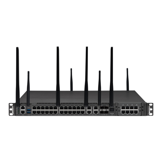
Page 16: Knowing Your Fta1170
For plugging a nano SIM card. Power and Reset Button Power on or turn off the system, or press and hold this button for 4 seconds to restart the system. Copyright © 2023 NEXCOM International Co., Ltd. All Rights Reserved. FTA 1170 User Manual... -
Page 17: Rear Panel
Chapter 1: Product Introduction Rear Panel LAN Module Slot LAN module bay to install add-on network modules. AC Power Inlets Connect the system to an AC power source. Copyright © 2023 NEXCOM International Co., Ltd. All Rights Reserved. FTA 1170 User Manual... -
Page 18: Chapter 2: Jumpers And Connectors
Static electricity can damage many of the electronic ▪ Use correct screws and do not over tighten screws. components. Humid environments tend to have less static electricity than Copyright © 2023 NEXCOM International Co., Ltd. All Rights Reserved. FTA 1170 Series User Manual... -
Page 19: Jumper Settings
(on) and open (off). Two-Pin Jumpers: Open (Left) and Short (Right) Three-Pin Jumpers: Pins 1 and 2 are Short Copyright © 2023 NEXCOM International Co., Ltd. All Rights Reserved. FTA 1170 Series User Manual... -
Page 20: Locations Of The Mainbaord Jumpers And Connectors
FTA 1170 Main Board Top View JP26 JP23 DIMM1 JP22 CON3 CN10 JP21 CN3 CN4 CON2 JP34 CON1 JP35 Copyright © 2023 NEXCOM International Co., Ltd. All Rights Reserved. FTA 1170 Series User Manual... -
Page 21: Jumpers
Connector type: 1 x 3 = 3 pin, 2.54mm Connector location: JP6 Connector location: JP7 Function Function Normal (Default) Normal (Default) Clear CMOS Clear CMOS Definition Definition N.C. N.C. RST_SOC_RTEST_N RST_SRTCRST_N Copyright © 2023 NEXCOM International Co., Ltd. All Rights Reserved. FTA 1170 Series User Manual... -
Page 22: Jtag Sel Header
JTAG SEL Header Connector type: 1 x 2 = 2 pin, 2.54mm Connector location: JP23 Function Open Normal (Default) Update MB CPLD firmware online. Definition JTAG_SEL Copyright © 2023 NEXCOM International Co., Ltd. All Rights Reserved. FTA 1170 Series User Manual... -
Page 23: Connector Pin Definitions
Connector type: 2 x 5 = 10 pin, 2.0mm Connector location: CN1 Definition Definition SMB_PMBUS_SML1_ SMB-ALERT_A_CAB STBY_LVC3_SDA SMB_PMBUS_SML1_ SMB-ALERT_B_CAB STBY_LVC3_SCL PSON_CAB PRESENT_IN_A_CAB PW_OK_A_CAB PRESENT_IN_B_CAB PW_OK_B_CAB N.C. Copyright © 2023 NEXCOM International Co., Ltd. All Rights Reserved. FTA 1170 Series User Manual... -
Page 24: Mini Pcie Slot
USB2_P2_DN CLK_M2_WIFI2_N N.C. USB2_P2_DP CLK_M2_WIFI2_P N.C. P3V3 N.C. P3V3 WIFI_LED_WWAN# N.C. WIFI_LED_WLAN# N.C. MPCIE_DIS# N.C. WIFI_LED_WPAN# MPCIE_RST N.C. P1V5 WIFI_RXN_1 P3V3 N.C. WIFI_RXP_1 N.C. P3V3 Copyright © 2023 NEXCOM International Co., Ltd. All Rights Reserved. FTA 1170 Series User Manual... -
Page 25: Sata Connector
Connector type: 2 x 3 = 6 pin, 4.2mm Connector location: CN3, CN4 Connector location: CN5 Definition Definition Definition P12V1 SATA1_TX_DP_C SATA0_TX_DP_C P12V1 SATA1_TX_DN_C SATA0_TX_DN_C P12V1 SATA1_RX_DN_C SATA0_RX_DN_C SATA1_RX_DP_C SATA0_RX_DP_C Copyright © 2023 NEXCOM International Co., Ltd. All Rights Reserved. FTA 1170 Series User Manual... - Page 26 Connector type: 2 x 5 = 10 pin, 2.0mm (4 GPI; 4 GPO) Connector location: CN6 Definition Definition P3V3_AUX CPLD_GPIN1 CPLD_GPOUT1 CPLD_GPIN2 CPLD_GPOUT2 CPLD_GPIN3 CPLD_GPOUT3 CPLD_GPIN4 CPLD_GPOUT4 Copyright © 2023 NEXCOM International Co., Ltd. All Rights Reserved. FTA 1170 Series User Manual...
-
Page 27: M.2 2280 Key M Pcie Slot
SSD_RXN_1 N.C. N.C. P3V3_SSD N.C. SSD_RXP_0 SSD_RXP_3 SSD_RXP_2 SSD_RXP_1 N.C. N.C. N.C. N.C. SSD_RXN_0 SSD_CONFIG_0 N.C. M.2_ACT_LED1 N.C. N.C. SSD_TXN_3_C SSD_TXN_2_C SSD_TXN_1_C N.C. P3V3_SSD N.C. Copyright © 2023 NEXCOM International Co., Ltd. All Rights Reserved. FTA 1170 Series User Manual... - Page 28 Chapter 2: Jumpers and Connectors Definition Definition SSD_TXN_0_C N.C. N.C. N.C. SSD_TXP_0_C CLK_32K_SUSCLK_SOC SSD_RST_N N.C. P3V3_SSD SSD_CLKREQ# CLK_M2_SSD_N P3V3_SSD MFG_CLK2 CLK_M2_SSD_P P3V3_SSD N.C. Copyright © 2023 NEXCOM International Co., Ltd. All Rights Reserved. FTA 1170 Series User Manual...
-
Page 29: Intel Xdp Connector (For Debug)
FM_LTB_CPU_DEBUG_EN_N TRC_PTI_DATA_R0 N.C. TRC_PTI_DATA_R15 SMB_SMT0_LTB_DATA TRC_PTI_DATA_R1 N.C. JTAG_PCH_TCK PU_P52_3V3 TRC_PTI_DATA_R2 N.C. TP_J5K1_54 DBP_LTB_MBP1_R_N (N.C.) TRC_PTI_DATA_R3 N.C. TP_J5K1_56 DBP_LTB_MBP0_R_N (N.C.) TRC_PTI_DATA_R4 N.C. TRC_PTI_DATA_R5 N.C. TRC_DFX_CLK1_R PD_LTB_P60 Copyright © 2023 NEXCOM International Co., Ltd. All Rights Reserved. FTA 1170 Series User Manual... -
Page 30: Board To Board Connector (Low Speed)
PU_NIC0_NCSI_RXD_0 IRQ_NIC0_WAKE_N N.C. USB2_P0_DN USB3_TX_P0_C BMC_CPLD_DSR_N PU_NIC0_NCSI_TXD_0 BMC_CPLD_RTS_N RST_CPLD_NIC_RESET_N N.C. USB2_P0_DP USB3_RX_N0_C BMC_CPLD_CTS_N PU_NIC0_NCSI_RXD_1 PU_NIC0_NCSI_TXD_1 SMB_ME_SMT1_ALRT_N IRQ_5GM2_WAKE_N USB3_RX_P0_C LED_GBE0_LED0_R BMC_CPLD_DCD_N PD_NIC0_NCSI_CRS_DV PD_NIC0_NCSI_TX_EN POWER_OK_EN USB2_P1_DN LED_GBE0_LED1_R Copyright © 2023 NEXCOM International Co., Ltd. All Rights Reserved. FTA 1170 Series User Manual... - Page 31 P3V3_S SMB_ME_SMT1_DATA LED_GBE2_LED0_R LED_GBE3_LED2_R CLK_100M_NIC0_DN P3V3_AUX LED_GBE0_LED2_R POE_LED LED_GBE2_LED1_R P12V2 CLK_100M_NIC0_DP P1E_NIC0_TX_C_DN P3V3_AUX P3V3_S LED_GBE1_LED0_R LED_GBE2_LED2_R WIFI_LED P12V2 P1E_NIC0_TX_C_DP P3V3_S LED_GBE1_LED1_R LED_GBE3_LED0_R HDD_CPLD_LED P1E_NIC0_RX_DN P3V3_S Copyright © 2023 NEXCOM International Co., Ltd. All Rights Reserved. FTA 1170 Series User Manual...
-
Page 32: 12V Power Connector
Connector size: 1 x 4 = 4 pin, 2.54mm Connector location: CON1 Connector location: CON2, CON3 Definition Definition Definition P12V2 P12V_S2 P12V2 P12V2 P12V2 P5V_S P12V2 P12V2 P12V2 P12V_AUX Copyright © 2023 NEXCOM International Co., Ltd. All Rights Reserved. FTA 1170 Series User Manual... -
Page 33: Run Bmc So-Dimm Connector
N.C. PWM1_GPIO12 I2C5SDA_GPIO34 N.C. N.C. GPIO25 N.C. GPIO0_SGPMLD N.C. I2C8SCL_GPIO26 N.C. PWM6_GPIO13 N.C. N.C. GPIO1_SGPMI PWM5_GPIO16 I2C8SDA_GPIO27 GPIO36 N.C. RNBMC_PRSNT#_R I2C13SDA FWSPIMISO_IO1 GPIO3_SGPMO N.C. GPIO37 Copyright © 2023 NEXCOM International Co., Ltd. All Rights Reserved. FTA 1170 Series User Manual... - Page 34 N.C. I2C2SDA_GPIO87 TACH0_GPIO44 N.C. N.C. A_VBAT_DETECT P1V05_A TACH1_GPIO46 TACH9_GPIO62 PECI I2C1SCL_GPIO88 N.C. N.C. N.C. N.C. TACH2_GPIO48 TACH10_GPIO64 I2C1SDA_GPIO90 WDTRST2_GPIO49 N.C. N.C. N.C. N.C. TACH11_GPIO66 N.C. Copyright © 2023 NEXCOM International Co., Ltd. All Rights Reserved. FTA 1170 Series User Manual...
- Page 35 PERSTN N.C. P12V2_ADC0 SYSCS#_GPIO112 I2C12SDA_GPIO99 PEREFCLKN ESPI_IO3_LPC_AD3 N.C. N.C. P3V3_AUX_ADC1 SPI_PCH_IBMC_DI PEREFCLKP ESPI_IO3_LPC_AD2 N.C. N.C. N.C. P5V_AUX_ADC2 SPI_PCH_IBMC_DO PERXN LPCCLK_ESPICLK N.C. GPIO102_UART4RX JTAG1TDO P3V3_SOC_ADC3 SPI_PCH_IBMC_CLK Copyright © 2023 NEXCOM International Co., Ltd. All Rights Reserved. FTA 1170 Series User Manual...
- Page 36 I2C3SCL_GPIO119 N.C. BMC_RESET# N.C. P1V2_VDDQ_ADC9 I2C3SDA_GPIO121 N.C. P3V_RTC_ADC13 SPI_IBMC_SSB_CLK RMIITXEN N.C. P5V_ADC10 N.C. N.C. N.C. P1V05_NAC_ADC11 SPI1CS1#_GPIO124 N.C. P1V8_A_ADC12 N.C. N.C. N.C. RMIIRXD0 N.C. N.C. Copyright © 2023 NEXCOM International Co., Ltd. All Rights Reserved. FTA 1170 Series User Manual...
-
Page 37: Fan Wafer Connector
Chapter 2: Jumpers and Connectors FAN Wafer Connector Connector size: 1 x 6 = 6 Pin, 1.25mm Connector location: J2, J3, J4 Definition P12V_S1 SYS_FAN1_TACH_R SYS_FAN1_PWM_R P12V_S1 Copyright © 2023 NEXCOM International Co., Ltd. All Rights Reserved. FTA 1170 Series User Manual... -
Page 38: Pcie Gen3 X16 Riser Card Board To Board Connector
PE_SOC_RX_DP7 PE_SOC_TX_C_DN2 PE_SOC_TX_C_DP7 PE_SOC_RX_DN2 PE_SOC_RX_DN7 PE_SOC_RX_DP0 PE_SOC_TX_C_DP2 PE_SOC_RX_DP5 PE_SOC_TX_C_DN7 PE_SOC_TX_C_DN0 PE_SOC_TX_C_DP5 PE_SOC_RX_DN0 PE_SOC_RX_DN5 PE_SOC_TX_C_DP0 PE_SOC_RX_DP3 PE_SOC_TX_C_DN5 PE_SOC_RX_DP8 PE_SOC_TX_C_DN3 PE_SOC_TX_C_DP8 PE_SOC_RX_DN3 PE_SOC_RX_DN8 PE_SOC_RX_DP1 PE_SOC_TX_C_DP3 PE_SOC_RX_DP6 PE_SOC_TX_C_DN8 Copyright © 2023 NEXCOM International Co., Ltd. All Rights Reserved. FTA 1170 Series User Manual... - Page 39 DISCONN_A2_EN PE_SOC_TX_C_DP12 P3V3_S PE_SOC_RX_DN12 DISCONN_A3_EN PE_SOC_RX_DP10 PE_SOC_TX_C_DN12 PE_SOC_RX_DP15 P3V3_S PE_SOC_TX_C_DP10 PE_SOC_TX_C_DP15 PE_SOC_RX_DN10 PE_SOC_RX_DN15 PE_SOC_TX_C_DN10 PE_SOC_RX_DP13 PE_SOC_TX_C_DN15 BYPASS_SLOT_EN PE_SOC_TX_C_DP13 P3V3_S PE_SOC_RX_DN13 BYPASS_SLOT_A PE_SOC_RX_DP11 PE_SOC_TX_C_DN13 CLK_PCIE_SLOT_P P3V3_S Copyright © 2023 NEXCOM International Co., Ltd. All Rights Reserved. FTA 1170 Series User Manual...
- Page 40 Definition Definition P12V_S2 N.C. BYPASS_SLOT_B P12V_S2 P3V3_AUX N.C. BYPASS_SLOT_C P3V3_AUX N.C. P12V_S2 N.C. BYPASS_SLOT_D P12V_S2 P12V_S2 N.C. N.C. P12V_S2 N.C. N.C. N.C. N.C. N.C. N.C. Copyright © 2023 NEXCOM International Co., Ltd. All Rights Reserved. FTA 1170 Series User Manual...
-
Page 41: Board To Board Connector (High Speed)
CR0_TX_DP2 SW_UART_RXD 3258_L0_RX_P_C TEMP_INT_N CR0_TX_DN2 P12V2 SW_UART_TXD CR0_TX_DP0 3258_L0_RX_N_C P12V_AUX PMD_L2_RX_P P12V2 CR0_TX_DN0 P12V_AUX 3258_MR_N PMD_L2_RX_N CR0_TX_DP3 PMD_L0_RX_P 3258_L1_RX_P_C RESETN1 CR0_TX_DN3 SMB_HOST_CLK PMD_L0_RX_N CR0_TX_DP1 3258_L1_RX_N_C Copyright © 2023 NEXCOM International Co., Ltd. All Rights Reserved. FTA 1170 Series User Manual... - Page 42 SMB_GBE2_I2C_CLK_R 5G_LTE_TX_DP1_C 5G_LTE_RX_DP2 3258_L3_TX_N SMB_GBE2_I2C_DATA_R 3258_L1_TX_P 5G_LTE_TX_DN1_C SMB_GBE0_I2C_CLK_R 5G_LTE_RX_DN2 3258_L3_RX_P_C 5G_LTE_RX_DP0_C 3258_L1_TX_N SMB_GBE0_I2C_DATA_R 3258_L3_RX_N_C CLK_OUT_DP6 5G_LTE_RX_DN0_C SMB_GBE3_I2C_CLK_R 5G_LTE_TX_DP2_C USB3_RX_P1_C CLK_OUT_DN6 SMB_GBE3_I2C_DATA_R 3258_L2_TX_P 5G_LTE_TX_DN2_C SMB_GBE1_I2C_CLK_R USB3_RX_N1_C Copyright © 2023 NEXCOM International Co., Ltd. All Rights Reserved. FTA 1170 Series User Manual...
- Page 43 Chapter 2: Jumpers and Connectors Definition Definition SMB_ETH_MNG_I2C_CLK_R PD_GBE_GPIO5_R SMB_CPLD_I2C_CLK_R SMB_ETH_MNG_I2C_DATA_R PEX_SW_RX_P SMB_CPLD_I2C_DATA_R PEX_SW_RX_N FM_GBE_GPIO2_PRSNT_3_ N_R RST_SW_LTB_RSTBTN_N RST_GBE_GPIO3_RST_1_N_R FM_SW_LTB_PWRBTN_N RST_GBE_GPIO6_RST_0_N_R PEX_SW_TX_P_C FM_GBE_GPIO7_INT_0_N_R PEX_SW_TX_N_C RST_GBE_GPIO0_RST_3_N_R CLK_100M_SW_DP FM_GBE_GPIO1_INT_3_N_R CLK_100M_SW_DN FM_GBE_GPIO4_INT_1_N_R Copyright © 2023 NEXCOM International Co., Ltd. All Rights Reserved. FTA 1170 Series User Manual...
-
Page 44: Core Power Pwm Smbus Header
Connector location: JP21* Connector location: JP22* Definition Definition PVCCIN_SCL PVNN_NAC_SCL PVCCIN_SDA PVNN_NAC_SDA These headers are designed to update VCCIN, PVNN_PCH PM ICs using a tool. Copyright © 2023 NEXCOM International Co., Ltd. All Rights Reserved. FTA 1170 Series User Manual... -
Page 45: Cpld Jtag Header
Connector size: 2 x 7 = 14 pin, 2.0mm Connector location: JP26 Connector location: JP34 Definition Definition Definition P3V3_AUX CLK_LPC_TPM H_LPC_FRAME_N JTAG_PLD_TCK ESPI_IO3_LPC_AD2 RST_TPM_N JTAG_PLD_TDO ESPI_IO3_LPC_AD1 ESPI_IO3_LPC_AD3 JTAG_PLD_TDI ESPI_IO3_LPC_AD0 JTAG_PLD_TMS INT_SERIRQ P3V3_SOC Copyright © 2023 NEXCOM International Co., Ltd. All Rights Reserved. FTA 1170 Series User Manual... -
Page 46: Cpld Jtag Header
Chapter 2: Jumpers and Connectors CPLD JTAG Header Connector size: 1 x 4 = 4 pin, 2.54mm Connector location: JP35 Definition P3V3_AUX BMC_CPLD_DEBUG_RXD BMC_CPLD_DEBUG_TXD Copyright © 2023 NEXCOM International Co., Ltd. All Rights Reserved. FTA 1170 Series User Manual... -
Page 47: Locations Of The Extension Board Connectors
The following figures show the extension board used in the FTA 1170, and indicates the locations of the connectors. Refer to this section for detailed pin settings and definitions of the connectors marked in pink on the figure below. FTA 1170 Extension Board Top View CN11 CN13 JP12 JP79 CN14 Copyright © 2023 NEXCOM International Co., Ltd. All Rights Reserved. FTA 1170 Series User Manual... -
Page 48: Connector Pin Definitions
N.C. N.C. POE2_ADDR2 N.C. POE3_ADDR2 N.C. N.C. N.C. N.C. N.C. N.C. N.C. N.C. N.C. N.C. N.C. N.C. V_3P3V_POE_MOD2 GND_POE2 V_3P3V_POE_MOD3 GND_POE3 V_3P3V_POE_MOD2 N.C. V_3P3V_POE_MOD3 N.C. Copyright © 2023 NEXCOM International Co., Ltd. All Rights Reserved. FTA 1170 Series User Manual... - Page 49 N.C. N.C. POE1_ADDR2 N.C. POE4_ADDR2 N.C. N.C. N.C. N.C. N.C. N.C. N.C. N.C. N.C. N.C. N.C. N.C. V_3P3V_POE_MOD1 GND_POE1 V_3P3V_POE_MOD4 GND_POE4 V_3P3V_POE_MOD1 N.C. V_3P3V_POE_MOD4 N.C. Copyright © 2023 NEXCOM International Co., Ltd. All Rights Reserved. FTA 1170 Series User Manual...
-
Page 50: Board To Board Connector (Low Speed)
N.C. USB2_P0_DN USB3_TX_P0 BMC_CPLD_DSR_N PU_NIC0_NCSI_TXD_0 BMC_CPLD_RTS_N RST_CPLD_NIC1_RESET_ N_R N.C. USB2_P0_DP USB3_RX_N0 BMC_CPLD_CTS_N PU_NIC0_NCSI_RXD_1 PU_NIC0_NCSI_TXD_1 SMB_NIC0_ALERT_N IRQ_5GM2_WAKE_N USB3_RX_P0 LED_GBE0_LED0 BMC_CPLD_DCD_N PD_NIC0_NCSI_CRS_DV PD_NIC0_NCSI_TX_EN MB_ ATX_PWROK USB2_P1_DN LED_GBE0_LED1 Copyright © 2023 NEXCOM International Co., Ltd. All Rights Reserved. FTA 1170 Series User Manual... - Page 51 P3V3_MB SMB_NIC0_DAT LED_GBE2_LED0 LED_GBE3_LED2 CLK_100M_NIC0_DN_R P3V3_AUX LED_GBE0_LED2 POE_LED LED_GBE2_LED1 P12V CLK_100M_NIC0_DP_R P1E_NIC0_TX_C_DN P3V3_AUX P3V3_MB LED_GBE1_LED0 LED_GBE2_LED2 WIFI_LED P12V P1E_NIC0_TX_C_DP P3V3_MB LED_GBE1_LED1 LED_GBE3_LED0 HDD_CPLD_LED P1E_NIC0_RX_DN P3V3_MB Copyright © 2023 NEXCOM International Co., Ltd. All Rights Reserved. FTA 1170 Series User Manual...
-
Page 52: Board To Board Connector (High Speed)
PMD_L2_TX_P SW_UART_RXD 3258_L0_RX_P TEMP_INT_N_R PMD_L2_TX_N P12V SW_UART_TXD PMD_L0_TX_P 3258_L0_RX_N P12V_AUX PMD_L2_RX_P P12V PMD_L0_TX_N P12V_AUX 3258_MR_N PMD_L2_RX_N PMD_L3_TX_P PMD_L0_RX_P 3258_L1_RX_P RESETN1_R PMD_L3_TX_N SMB_HOST_CLK PMD_L0_RX_N PMD_L1_TX_P 3258_L1_RX_N Copyright © 2023 NEXCOM International Co., Ltd. All Rights Reserved. FTA 1170 Series User Manual... - Page 53 TP_SMB_GBE2_I2C_CLK 5G_LTE_TX_DP1 5G_LTE_RX_DP2 88X3310P_L1_TX_N TP_SMB_GBE2_I2C_DATA 3258_L1_TX_P 5G_LTE_TX_DN1 SMB_GBE0_I2C_CLK 5G_LTE_RX_DN2 88X3310P_L1_RX_P N.C. 3258_L1_TX_N SMB_GBE0_I2C_DATA 88X3310P_L1_RX_N CLK_OUT_DP6 N.C. TP_SMB_GBE3_I2C_CLK 5G_LTE_TX_DP2 USB3_RX_P1 CLK_OUT_DN6 TP_SMB_GBE3_I2C_DATA 88X3310P_L0_TX_P 5G_LTE_TX_DN2 TP_SMB_GBE1_I2C_CLK USB3_RX_N1 Copyright © 2023 NEXCOM International Co., Ltd. All Rights Reserved. FTA 1170 Series User Manual...
- Page 54 X557_MDIO_SDA PEX_SW_RX_P_C SMB_CPLD_I2C_DATA_R FM_GBE_GPIO2_ PEX_SW_RX_N_C PRSNT_3_ N_R RST_SW_LTB_RSTBTN_N RST_GBE_GPIO3_RST_1_ N_R FM_SW_LTB_PWRBTN_N RST_GBE_GPIO6_RST_0_ N_R PEX_SW_TX_P FM_GBE_GPIO7_INT_0_N_ R PEX_SW_TX_N RST_GBE_GPIO0_RST_3_ N_R CLK_100M_SW_DP_R FM_GBE_GPIO1_INT_3_N_ R CLK_100M_SW_DN_R FM_GBE_GPIO4_INT_1_N_ R Copyright © 2023 NEXCOM International Co., Ltd. All Rights Reserved. FTA 1170 Series User Manual...
-
Page 55: Reset Button Header
Connector size: 1 x 2 = 2 Pin, 2.0mm Connector size: 1 x 2 = 2 Pin, 2.54mm Connector location: CN14 Connector location: JP1 Definition Definition FP_RST_BTN_N_R PWRBTN#_C Copyright © 2023 NEXCOM International Co., Ltd. All Rights Reserved. FTA 1170 Series User Manual... -
Page 56: Poe Box Header (Connector To Poe Module)
POE1_DETECT N.C. VPORT_NEG_OUT1 V_52V_OUT N.C. N.C. DRG_SPI_SCK VPORT_NEG_OUT3 V_52V_OUT V_52V_OUT VPORT_NEG_OUT6 N.C. P3V3 DRG_SPI_MISO N.C. V_52V_OUT VPORT_NEG_OUT8 N.C. N.C. P3V3 DRG_SPI_CS VPORT_NEG_OUT2 V_52V_OUT N.C. VPORT_NEG_OUT5 Copyright © 2023 NEXCOM International Co., Ltd. All Rights Reserved. FTA 1170 Series User Manual... - Page 57 POE2_DETECT N.C. VPORT_NEG_OUT9 V_52V_OUT N.C. N.C. DRG_SPI_SCK VPORT_NEG_OUT11 V_52V_OUT V_52V_OUT VPORT_NEG_OUT14 N.C. P3V3 DRG_SPI_MISO N.C. V_52V_OUT VPORT_NEG_OUT16 N.C. N.C. P3V3 DRG_SPI_CS VPORT_NEG_OUT10 V_52V_OUT N.C. VPORT_NEG_OUT13 Copyright © 2023 NEXCOM International Co., Ltd. All Rights Reserved. FTA 1170 Series User Manual...
- Page 58 POE3_DETECT N.C. VPORT_NEG_OUT17 V_52V_OUT N.C. N.C. DRG_SPI_SCK VPORT_NEG_OUT19 V_52V_OUT V_52V_OUT VPORT_NEG_OUT22 N.C. P3V3 DRG_SPI_MISO N.C. V_52V_OUT VPORT_NEG_OUT24 N.C. N.C. P3V3 DRG_SPI_CS VPORT_NEG_OUT18 V_52V_OUT N.C. VPORT_NEG_OUT21 Copyright © 2023 NEXCOM International Co., Ltd. All Rights Reserved. FTA 1170 Series User Manual...
- Page 59 POE4_DETECT N.C. VPORT_NEG_10G_OUT1 V_52V_OUT N.C. N.C. DRG_SPI_SCK VPORT_NEG_10G_OUT3 V_52V_OUT V_52V_OUT VPORT_NEG_10G_OUT6 N.C. P3V3 DRG_SPI_MISO N.C. V_52V_OUT VPORT_NEG_10G_OUT8 N.C. N.C. P3V3 DRG_SPI_CS VPORT_NEG_10G_OUT2 V_52V_OUT N.C. VPORT_NEG_10G_OUT5 Copyright © 2023 NEXCOM International Co., Ltd. All Rights Reserved. FTA 1170 Series User Manual...
-
Page 60: I/O Board Cpld Jtag Header
Connector size: 1 x 6 = 6 Pin , 2.54mm Connector location: JP12 Definition P3V3_AUX JTAG_CPLD_TCK JTAG_CPLD_TDO JTAG_CPLD_TDI JTAG_CPLD_TMS This header is designed to update CPLD firmware with a diamond programmer. Copyright © 2023 NEXCOM International Co., Ltd. All Rights Reserved. FTA 1170 Series User Manual... -
Page 61: Block Diagram
Chapter 2: Jumpers and Connectors Block Diagram FTA1170 Copyright © 2023 NEXCOM International Co., Ltd. All Rights Reserved. FTA 1170 Series User Manual... -
Page 62: Fta1170A
Chapter 2: Jumpers and Connectors FTA1170A Copyright © 2023 NEXCOM International Co., Ltd. All Rights Reserved. FTA 1170 Series User Manual... -
Page 63: Chapter 3: System Setup
With the screws removed, gently slide the cover outwards and then lift to prevent electric shock or system damage. up the cover to remove it. Copyright © 2023 NEXCOM International Co., Ltd. All Rights Reserved. FTA 1170 Series User Manual... -
Page 64: Installing Memory Modules
A1 and B1, followed by A0 and B0. Refer to Chapter 2 even pressure to both ends of the modules until they slip into the the mechanical location and sequence of DIMM slots. sockets. Copyright © 2023 NEXCOM International Co., Ltd. All Rights Reserved. FTA 1170 Series User Manual... -
Page 65: Installing An M.2 Key M Storage Device
Insert the M.2 SSD into the M.2 slot at a 45 degree angle until the gold -plated connector on the edge of the module completely disappears inside the slot. Copyright © 2023 NEXCOM International Co., Ltd. All Rights Reserved. FTA 1170 Series User Manual... - Page 66 Chapter 3: System Setup With the module fully inserted, tighten a screw into the mounting hole on the module to secure it. Copyright © 2023 NEXCOM International Co., Ltd. All Rights Reserved. FTA 1170 Series User Manual...
-
Page 67: Installing A Bmc Module
Insert the BMC module into the BMC socket at a 45 degree angle until the gold-plated connector on the edge of the module completely disappears inside the slot. Copyright © 2023 NEXCOM International Co., Ltd. All Rights Reserved. FTA 1170 Series User Manual... - Page 68 Push the module down until the clips on both sides of the socket lock into position. A distinctive "click" sound will indicate the module is correctly locked into place. Copyright © 2023 NEXCOM International Co., Ltd. All Rights Reserved. FTA 1170 Series User Manual...
-
Page 69: Installing A 2.5" Sata Hard Drive
Tighten the hard drive with screws on both sides of the bracket. The bracket is designed to support the assembly of up to 2 hard drives. Copyright © 2023 NEXCOM International Co., Ltd. All Rights Reserved. FTA 1170 Series User Manual... - Page 70 Connect the SATA data and power cables from the hard drive(s) to the which it was previously removed on the chassis. motherboard. CON2 CON3 CN4 Copyright © 2023 NEXCOM International Co., Ltd. All Rights Reserved. FTA 1170 Series User Manual...
-
Page 71: Chapter 4: Bios Setup
BIOS is updated in the future. second, to make settings appropriate for the way you use the computer. To check for the latest updates and revisions, visit the NEXCOM website at When to Configure the BIOS www.nexcom.com.tw. -
Page 72: Default Configuration
Powering on the computer and immediately pressing allows you to enter Setup. Load optimized default values. Saves and exits the Setup program. Press <Enter> to enter the highlighted sub-menu Copyright © 2023 NEXCOM International Co., Ltd. All Rights Reserved. FTA 1170 Series User Manual... - Page 73 When “” appears on the left of a particular field, it indicates that a submenu which contains additional options are available for that field. To display the submenu, move the highlight to that field and press Copyright © 2023 NEXCOM International Co., Ltd. All Rights Reserved. FTA 1170 Series User Manual...
-
Page 74: Bios Setup Utility
00 to 23. Minute displays minutes from 00 to 59. Second displays The Main menu is the first screen that you will see when you enter the BIOS seconds from 00 to 59. Setup Utility. Copyright © 2023 NEXCOM International Co., Ltd. All Rights Reserved. FTA 1170 Series User Manual... -
Page 75: Advanced
Enable or disable BIOS support for security device. O.S will not show Security Device. TCG EFI protocol and INT1A interface will not be available. Disable Block Sid Override to allow SID authentication in TCG storage device. Copyright © 2023 NEXCOM International Co., Ltd. All Rights Reserved. FTA 1170 Series User Manual... - Page 76 Display the super I/O chip used on the board. Change Settings Serial Port 1 Configuration Select an optimal setting for the Super IO device. Enter Serial Port 1 Configuration submenu. Copyright © 2023 NEXCOM International Co., Ltd. All Rights Reserved. FTA 1170 Series User Manual...
- Page 77 Control the NVRAM runtime variable protection through system admin password. Console Redirection Enable or disable the console redirection. Console Redirection Settings When Console Redirection is enabled, Console Redirection Settings will be available. Copyright © 2023 NEXCOM International Co., Ltd. All Rights Reserved. FTA 1170 Series User Manual...
- Page 78 Selects the serial port transmission speed. The speed must match the other Selects the Putty keyboard emulation type. side. Long or noisy lines may require a lower speed. Copyright © 2023 NEXCOM International Co., Ltd. All Rights Reserved. FTA 1170 Series User Manual...
- Page 79 This section is used to configure the PCI. Above 4G Decoding Enable or disable the decoding of 64-bit devices in 4G address space. SR-IOV Support Enable or disable the SR-IOV support. Copyright © 2023 NEXCOM International Co., Ltd. All Rights Reserved. FTA 1170 Series User Manual...
- Page 80 XHCI Hand-off This is a workaround for OSes that does not support XHCI hand-off. The XHCI ownership change should be claimed by the XHCI driver. Copyright © 2023 NEXCOM International Co., Ltd. All Rights Reserved. FTA 1170 Series User Manual...
- Page 81 Enable or disable IPv4 PXE support. If disabled, the IPv4 boot option will not be created. Ipv4 HTTP Support Enable or disable Ipv4 HTTP support. Copyright © 2023 NEXCOM International Co., Ltd. All Rights Reserved. FTA 1170 Series User Manual...
- Page 82 Run Device Self Test Run the device self test according to the self test option and action selected. Pressing the Esc key will abort the test. Copyright © 2023 NEXCOM International Co., Ltd. All Rights Reserved. FTA 1170 Series User Manual...
- Page 83 Mass storage device emulation type. "Auto" enumerates devices less than 530MB as floppies. Forced FDD option can be used to force HDD formatted drive to boot as FDD. Copyright © 2023 NEXCOM International Co., Ltd. All Rights Reserved. FTA 1170 Series User Manual...
-
Page 84: Platform Configuration
PCI Express Configuration / Fia Mux Configuration / SATA Configuration PCH Configuration / USB Configuration / SCS Configuration Enter the PCH Configuration submenu. Press Enter to access each submenu. Copyright © 2023 NEXCOM International Co., Ltd. All Rights Reserved. FTA 1170 Series User Manual... - Page 85 Chapter 3: BIOS Setup PCI Express Configuration PCI Express Root Port 1~12 Press Enter to access each submenu and configure each option. Copyright © 2023 NEXCOM International Co., Ltd. All Rights Reserved. FTA 1170 Series User Manual...
- Page 86 Force L0 Forces all links to L0 state. Auto The BIOS automatically selects an ASPM level. Disable Disables ASPM L1 Substates Configure the L1 Substates settings. Copyright © 2023 NEXCOM International Co., Ltd. All Rights Reserved. FTA 1170 Series User Manual...
- Page 87 SATA Configuration FIA Mux Configuration Controller 3 SATA Configuration By enabling this you override the platform configuration on FIA/WM. Enter the Controller 3 SATA Configuration submenu. Copyright © 2023 NEXCOM International Co., Ltd. All Rights Reserved. FTA 1170 Series User Manual...
- Page 88 Software Feature Mask Configuration for Controller 3 Enable or disable software feature mask configuration for controller 3. Aggressive LPM Support Enable or disable aggressive LPM support. Copyright © 2023 NEXCOM International Co., Ltd. All Rights Reserved. FTA 1170 Series User Manual...
- Page 89 Selectively enable or disable the corresponding USB port from reporting a Enable or disable SCS eMMC 5.1 controller. device connection to the controller. eMMC 5.1 HS400 Mode Enable or disable eMMC 5.1 HS400 mode. Copyright © 2023 NEXCOM International Co., Ltd. All Rights Reserved. FTA 1170 Series User Manual...
-
Page 90: Socket Configuration
Chapter 3: BIOS Setup Socket Configuration Processor Configuration / Memory Configuration / IIO Configuration / Advanced Power Management Configuration Press Enter to access each submenu. Copyright © 2023 NEXCOM International Co., Ltd. All Rights Reserved. FTA 1170 Series User Manual... - Page 91 CPUs with extended CPUID function. Hardware Prefetcher Enable or disable the MLC streamer prefetcher. Copyright © 2023 NEXCOM International Co., Ltd. All Rights Reserved. FTA 1170 Series User Manual...
- Page 92 Intel VT for Directed I/O (VT-d) Press Enter to see the information on the memory installed. Enter the Intel VT for Directed I/O (VT-d) submenu. Copyright © 2023 NEXCOM International Co., Ltd. All Rights Reserved. FTA 1170 Series User Manual...
- Page 93 Chapter 3: BIOS Setup Socket0 Configuration IOU0 (II0 PCIe Port 1) Select PCIe port bifurcation for selected slot(s). Port 1A Enter the Port 1A submenu. Copyright © 2023 NEXCOM International Co., Ltd. All Rights Reserved. FTA 1170 Series User Manual...
- Page 94 Configure the link speed for the PCIe port. Override Max Link Width Configure the link speed to override the max link width set by bifurcation. Copyright © 2023 NEXCOM International Co., Ltd. All Rights Reserved. FTA 1170 Series User Manual...
- Page 95 Enable or disable EIST (P-States). CPU C State Control Energy Efficient Turbo Enter the CPU C State Control submenu. Enable or disable Energy Efficient Turbo. Copyright © 2023 NEXCOM International Co., Ltd. All Rights Reserved. FTA 1170 Series User Manual...
- Page 96 Enable or disable CPU C1 auto demotion. CPU C1 auto undemotion Enable or disable CPU C1 auto undemotion. CPU C6 report Enable or disable C6 report to the operating system. Copyright © 2023 NEXCOM International Co., Ltd. All Rights Reserved. FTA 1170 Series User Manual...
-
Page 97: Security
Chapter 3: BIOS Setup Security Administrator Password Set the administrator’s password for the system. Copyright © 2023 NEXCOM International Co., Ltd. All Rights Reserved. FTA 1170 Series User Manual... -
Page 98: Boot
When set to Off, the function of the numeric keypad is the arrow keys. Quiet Boot Enable or disable the quiet boot function. Copyright © 2023 NEXCOM International Co., Ltd. All Rights Reserved. FTA 1170 Series User Manual... -
Page 99: Save & Exit
<ESC> to exit without saving the changes. Restore Defaults To restore the BIOS to default settings, select this field then press <Enter>. A dialog box will appear. Confirm by selecting Yes. Copyright © 2023 NEXCOM International Co., Ltd. All Rights Reserved. FTA 1170 Series User Manual...
Need help?
Do you have a question about the FTA 1170 Series and is the answer not in the manual?
Questions and answers