
Related Manuals for Nexcom NSA 3150


Summary of Contents for Nexcom NSA 3150
- Page 1 NEXCOM International Co., Ltd. Network and Communication Solutions Network Security Appliance NSA 3150 User Manual NEXCOM International Co., Ltd. www.nexcom.com Published April 2016...
-
Page 2: Table Of Contents
Knowing Your NSA 3150 ................3 GAL Programming Connector ............17 Front Panel ..................3 Power Connector ................17 Rear Panel ...................4 System Fan Connectors (4-Pin) ............18 System Fan Connectors (3-Pin) ............18 Copyright © 2013 NEXCOM International Co., Ltd. All Rights Reserved. NSA 3150 User Manual... - Page 3 Default Configuration ................37 Entering Setup ..................37 Legends ....................37 BIOS Setup Utility ..................39 Main ....................39 Advanced ..................40 Chipset ....................50 Boot ....................52 Security .....................53 Save & Exit ..................53 Copyright © 2013 NEXCOM International Co., Ltd. All Rights Reserved. NSA 3150 User Manual...
-
Page 4: Preface
Acknowledgements The product(s) described in this manual complies with all applicable NSA 3150 is a trademark of NEXCOM International Co., Ltd. All other product European Union (CE) directives if it has a CE marking. For computer systems names mentioned herein are registered trademarks of their respective owners. -
Page 5: Rohs Compliance
0.1% or 1,000ppm, and Polybrominated diphenyl Ethers (PBDE) < 0.1% or 1,000ppm. In order to meet the RoHS compliant directives, NEXCOM has established an engineering and manufacturing task force in to implement the introduction of green products. The task force will ensure that we follow the standard... -
Page 6: Warranty And Rma
(manuals, cable, etc.) and any components from the card, such as CPU and RAM. If the components were suspected as part of the problems, ▪ If RMA goods can not be repaired, NEXCOM will return it to the customer please note clearly which components are included. Otherwise, NEXCOM without any charge. - Page 7 ESD workstation. If no such station is available, you can provide some ESD protection by wearing an antistatic wrist strap and attaching it to a metal part of the computer chassis. Copyright © 2013 NEXCOM International Co., Ltd. All Rights Reserved. NSA 3150 User Manual...
-
Page 8: Safety Information
There is a danger of explosion if battery is incorrectly replaced. Replace only with the same or equivalent type recommended by the manufacturer. Discard used batteries according to the manufacturer’s instructions. viii Copyright © 2013 NEXCOM International Co., Ltd. All Rights Reserved. NSA 3150 User Manual... -
Page 9: Safety Precautions
RECOMMENDED BY THE MANUFACTURER. DISCARD USED BATTERIES ACCORDING TO THE MANUFACTURER’S INSTRUCTIONS. 10. All cautions and warnings on the equipment should be noted. Copyright © 2013 NEXCOM International Co., Ltd. All Rights Reserved. NSA 3150 User Manual... -
Page 10: Technical Support And Assistance
Preface Technical Support and Assistance Conventions Used in this Manual 1. For the most updated information of NEXCOM products, visit NEXCOM’s Warning: website at www.nexcom.com. Information about certain situations, which if not observed, can cause personal injury. This will prevent injury to yourself 2. -
Page 11: Global Service Contact Information
13F, No.920, Chung-Cheng Rd., ZhongHe District, Beijing, 100094, China New Taipei City, 23586, Taiwan, R.O.C. Tel: +86-10-5704-2680 Tel: +886-2-8226-7796 Fax: +86-10-5704-2681 Fax: +886-2-8226-7792 Email: sales@nexcom.cn Email: sales@nexcom.com.tw www.nexcom.cn www.nexcom.com.tw Copyright © 2013 NEXCOM International Co., Ltd. All Rights Reserved. NSA 3150 User Manual... - Page 12 Hui Yin Ming Zun Building Room 1108, Building No. 11, 599 Yunling Road, Putuo District, Shanghai, 200062, China Tel: +86-21-6125-8282 Fax: +86-21-6125-8281 Email: frankyang@nexcom.cn www.nexcom.cn Copyright © 2013 NEXCOM International Co., Ltd. All Rights Reserved. NSA 3150 User Manual...
-
Page 13: Package Contents
Preface Package Contents Before continuing, verify that the NSA 3150 package that you received is complete. Your package should have all the items listed in the following table. Item Part Number Name Description 19S00315000X0 NSA3150 ASSY 50311F0102X00 (H)Round Head Screw Long FEI:P6#32Tx 1/4/SW7*0.8 W/Spring+Flat Washer P6#32Tx 1/4/SW7x0.8 NI... -
Page 14: Ordering Information
Preface Ordering Information The following below provides ordering information for NSA 3150. Barebone NSA 3150 (P/N: 10S00315000X0) Support 4th generation Intel ® Core™ processors, 2 DDR3 memory slots, 8PCIe GbE LAN ports, USB ports, VGA port, w/o LCM Copyright © 2013 NEXCOM International Co., Ltd. All Rights Reserved. -
Page 15: Chapter 1: Product Introduction
▪ Internal one 3.5” HDD bay/two 2.5” HDD bay (Optional) ▪ 4th generation Intel Core™ processors ® ▪ Support two DDR3 1333/1600 memory, up to 16GB Copyright © 2013 NEXCOM International Co., Ltd. All Rights Reserved. NSA 3150 User Manual... -
Page 16: Hardware Specifications
▪ 2x USB 2.0 ports Certifications ▪ 1x RJ45 type console port ▪ CE approval ▪ 8x copper LAN ports ▪ FCC Class A ▪ 1x LAN module ▪ UL Copyright © 2013 NEXCOM International Co., Ltd. All Rights Reserved. NSA 3150 User Manual... -
Page 17: Knowing Your Nsa 3150
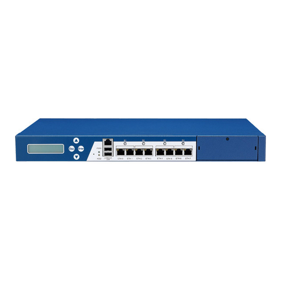
Used to connect RJ45 type console port. USB Ports Used to connect USB 2.0/1.1 devices. Copper LAN Ports Used to connect LAN network devices. Power/HDD LEDs Copper LAN ports ports Copyright © 2013 NEXCOM International Co., Ltd. All Rights Reserved. NSA 3150 User Manual... -
Page 18: Rear Panel
Used to connect USB 2.0/1.1 devices. AC Power Socket Plug an AC power cord here before turning on the system. Expansion slot AC Power Socket (optional) Copyright © 2013 NEXCOM International Co., Ltd. All Rights Reserved. NSA 3150 User Manual... -
Page 19: Chapter 2: Jumpers And Connectors
Static electricity can damage many of the electronic ▪ Use correct screws and do not over tighten screws. components. Humid environments tend to have less static electricity than Copyright © 2013 NEXCOM International Co., Ltd. All Rights Reserved. NSA 3150 User Manual... -
Page 20: Jumper Settings
(on) and open (off). Two-Pin Jumpers: Open (Left) and Short (Right) Three-Pin Jumpers: Pins 1 and 2 are Short Copyright © 2013 NEXCOM International Co., Ltd. All Rights Reserved. NSA 3150 User Manual... -
Page 21: Locations Of The Jumpers And Connectors
The figure below shows the location of the jumpers and connectors. GFM1 PCIE1 JINTRUDER CON3 JPRSNT1 FAN4 FAN3 CON5 FAN1 JP5 J10 FAN2 SATA3 COM1 LED9 SATA1 SATA2 JKBMS1 JPWRBTN1 CON1 JWDTO1 CON2 JRST1 JVGA1 JUSB1 Copyright © 2013 NEXCOM International Co., Ltd. All Rights Reserved. NSA 3150 User Manual... -
Page 22: Jumpers
Connector type: 1x3 3-pin header, 2.54mm pitch Connector location: JP2 Connector location: JP1 Function Function Normal ATX Mode Clear CMOS AT Mode Definition Definition VCCRTC RTC_RST# AT_ATX_SELECT Copyright © 2013 NEXCOM International Co., Ltd. All Rights Reserved. NSA 3150 User Manual... -
Page 23: Console Pin Header
Chapter 2: Jumpers and Connectors Console Pin Header Connector type: 1x3 3-pin header, 2.54mm pitch Connector location: JP5 Function RTS to CTS Normal Description SP_RTS1_R SP_CTS1_R SP_CTS1_CON Copyright © 2013 NEXCOM International Co., Ltd. All Rights Reserved. NSA 3150 User Manual... -
Page 24: Connector Pin Definitions
Dual USB 2.0 ports, Type A Connector location: CN2 Definition Definition Definition Definition SP_RTS1_R SP_DTR1_R 5VDUAL 5VDUAL SP_TXD1_R USB2- USB3- SP_DCD1_R SP_RXD1_R USB2+ USB3+ SP_DSR1_R SP_CTS1_CON Copyright © 2013 NEXCOM International Co., Ltd. All Rights Reserved. NSA 3150 User Manual... -
Page 25: Lan Ports
LAN3_LED_ACT# LAN3_ACTPW LAN2_TXP0_CON LAN2_TXN0_CON LAN4_TXP0_CON LAN4_TXN0_CON LAN2_TXP1_CON LAN2_TXP2_CON LAN4_TXP1_CON LAN4_TXP2_CON LAN2_TXN2_CON LAN2_TXN1_CON LAN4_TXN2_CON LAN4_TXN1_CON LAN2_TXP3_CON LAN2_TXN3_CON LAN4_TXP3_CON LAN4_TXN3_CON LAN2_LED_LINK1G# LAN2_LED_LINK100# LAN4_LED_LINK1G# LAN4_LED_LINK100# LAN2_LED_ACT# LAN2_ACTPW LAN4_LED_ACT# LAN4_ACTPW Copyright © 2013 NEXCOM International Co., Ltd. All Rights Reserved. NSA 3150 User Manual... - Page 26 LAN7_LED_ACT# LAN7_ACTPW LAN6_TXP0_CON LAN6_TXN0_CON LAN8_TXP0_CON LAN8_TXN0_CON LAN6_TXP1_CON LAN6_TXP2_CON LAN8_TXP1_CON LAN8_TXP2_CON LAN6_TXN2_CON LAN6_TXN1_CON LAN8_TXN2_CON LAN8_TXN1_CON LAN6_TXP3_CON LAN6_TXN3_CON LAN8_TXP3_CON LAN8_TXN3_CON LAN6_LED_LINK1G# LAN6_LED_LINK100# LAN8_LED_LINK1G# LAN8_LED_LINK100# LAN6_LED_ACT# LAN6_ACTPW LAN8_LED_ACT# LAN8_ACTPW Copyright © 2013 NEXCOM International Co., Ltd. All Rights Reserved. NSA 3150 User Manual...
-
Page 27: Reset Button
Chapter 2: Jumpers and Connectors Reset Button Connector location: SW1 Definition SW_BTN_IN Copyright © 2013 NEXCOM International Co., Ltd. All Rights Reserved. NSA 3150 User Manual... -
Page 28: Connector Pin Definitions
Connector location: J8 Connector location: COM1 Definition Definition Definition Definition VCC5 SP_DCD2 SP_RXD2 SIO_GP32 SIO_GP06 SP_TXD2 SP_DTR2 SIO_GP03 SIO_GP07 SP_DSR2 SIO_GP04 SIO_GP76 SP_RTS2 SP_CTS2 SIO_GP05 SIO_GP77 SP_RI2 Copyright © 2013 NEXCOM International Co., Ltd. All Rights Reserved. NSA 3150 User Manual... -
Page 29: Usb2 Jst Header Connector
Connector type: 1x6 6-pin header, 2.0mm pitch Connector type: 1x2 2-pin header, 2.54mm pitch Connector location: JUSB1 Connector location: JRST1 Definition Definition Definition 5VDUAL USB0- PCH_SYS_RESET_N_R USB0+ USB1- USB1+ Copyright © 2013 NEXCOM International Co., Ltd. All Rights Reserved. NSA 3150 User Manual... -
Page 30: Power Button Pin Header
Connector type: 1x2 2-pin header, 2.54mm pitch Connector location: JPWRBTN1 Connector location: J9, J10, J11 and J12 Definition Definition VCC3 BYPASS_LED_S4 FP_PWRBTN_N Definition VCC3 BYPASS_LED_S3 Definition VCC3 BYPASS_LED_S2 Definition VCC3 BYPASS_LED_S1 Copyright © 2013 NEXCOM International Co., Ltd. All Rights Reserved. NSA 3150 User Manual... -
Page 31: Gal Programming Connector
Connector type: 1x6 6-pin header, 2.54mm pitch Connector type: 1x4 4-pin header, 5.08mm pitch Connector location: J2 Connector location: J3 Definition Definition Definition Definition 3VSB VCC12 GAL_TCK GAL_TDO VCC5 GAL_TDI GAL_TMS Copyright © 2013 NEXCOM International Co., Ltd. All Rights Reserved. NSA 3150 User Manual... -
Page 32: System Fan Connectors (4-Pin)
Connector type: 1x4 4-pin Wafer, 2.54mm pitch Connector type: 1x3 3-pin Wafer, 2.54mm pitch Connector location: FAN1 and FAN3 Connector location: FAN2 and FAN4 Definition Definition VCC12 VCC12 Sense Sense FANPWM Copyright © 2013 NEXCOM International Co., Ltd. All Rights Reserved. NSA 3150 User Manual... -
Page 33: Sata Connectors
Connector location: J5 SATA1 Definition Definition Definition SATA_TX2P VCC5 SATA_TX2N SATA_RX2N SATA_RX2P SATA2 Definition Definition SATA_TX0P SATA_TX0N SATA_RX0N SATA_RX0P SATA3 Definition Definition SATA_TX1P SATA_TX1N SATA_RX1N SATA_RX1P Copyright © 2013 NEXCOM International Co., Ltd. All Rights Reserved. NSA 3150 User Manual... -
Page 34: Keyboard/Mouse Connector
Connector type: 2x8 16-pin header, 2.0mm pitch Connector location: JKBMS1 Connector location: JVGA1 Definition Definition Definition Definition VCC5 VCC5 RED_VGA GREEN_VGA KDAT MDAT BLUE_VGA KCLK MCLK VGA_+5V DDC_DATA_VGA HSYNC_VGA VSYNC_VGA DDC_CLK_VGA Copyright © 2013 NEXCOM International Co., Ltd. All Rights Reserved. NSA 3150 User Manual... -
Page 35: Parallel Interface For Lcm Module
Connector location: JP6 Definition Definition Definition Definition VCC5 KEY_PIN1 KEY_PIN2 LPT_SLIN#R LPT_RES KEY_PIN3 KEY_PIN4 LPT_AFD#R LPT_INIT#R LPT_PDR1 LPT_PDR0 LPT_PDR3 LPT_PDR2 LPT_PDR5 LPT_PDR4 LPT_PDR7 LPT_PDR6 LPT_PW VCC5 Copyright © 2013 NEXCOM International Co., Ltd. All Rights Reserved. NSA 3150 User Manual... -
Page 36: Power Connector
Connector location: CON1 Connector location: CON2 Definition Definition Definition Definition VCC3 VCC3 VCC5 VCC12_CPU VCC12_CPU VCC5 ATXPWROK 5VSB VCC12 VCC12 VCC3 VCC3 NVCC12 SIO_PSON_N VCC5 VCC5 VCC5 Copyright © 2013 NEXCOM International Co., Ltd. All Rights Reserved. NSA 3150 User Manual... -
Page 37: Pcie X8 Slot
VCC3 3VSB PEG_STXN5 RST_X8_SLOT_N PCIE_WAKE_L PEG_SRXP5 PEG_SRXN5 CK_SLOT2_DP PEG_STXP6 CK_SLOT2_DN PEG_STXP0 PEG_STXN6 PEG_STXN0 PEG_SRXP6 PEG_SRXP0 PEG_SRXN6 PEG_SRXN0 PCIe_PRSNT PEG_STXP7 PEG_STXN7 PEG_STXP1 PEG_SRXP7 PEG_STXN1 PEG_SRXN7 PCIe_PRSNT PEG_SRXP1 Copyright © 2013 NEXCOM International Co., Ltd. All Rights Reserved. NSA 3150 User Manual... -
Page 38: Pcie Golden Finger (For Lan Module)
PEG_TXN5 PEG_RXN5 VCC3_3 3VSB CK_SLOT1_DP 3VSB PEG_TXP6 PEG_RXP6 CK_SLOT1_DN 3VSB PEG_TXN6 PEG_RXN6 VCC3_3 USB_4P CLK_GF_33M USB_4N PEG_TXP7 PEG_RXP7 VCC3_3 VCC3_3 PEG_TXN7 PEG_RXN7 AUX_TEMP VCC3_3 CPU- VCC3_3 Copyright © 2013 NEXCOM International Co., Ltd. All Rights Reserved. NSA 3150 User Manual... -
Page 39: Chapter 3: System Setup
1. Remove the screws on the chassis cover then put them in a safe place for 2. Gently slide the cover outwards, then lift up the cover to remove it. later use. Lift here Copyright © 2013 NEXCOM International Co., Ltd. All Rights Reserved. NSA 3150 User Manual... -
Page 40: Installing A Sata Dom
Chapter 3: System Setup Installing a SATA DOM 1. Locate the SATA DOM connector on the board. 2. Fasten a copper post on the mounting hole. Copyright © 2013 NEXCOM International Co., Ltd. All Rights Reserved. NSA 3150 User Manual... - Page 41 3. Install the SATA DOM to the connector with the mounting hole aligned 4. Fasten a screw on top of the copper post. to the copper post. Copyright © 2013 NEXCOM International Co., Ltd. All Rights Reserved. NSA 3150 User Manual...
- Page 42 Chapter 3: System Setup 5. Connect the power cable to the power connector on the board. Copyright © 2013 NEXCOM International Co., Ltd. All Rights Reserved. NSA 3150 User Manual...
-
Page 43: Installing Dimm Memory Modules
2. Release the locks on the DIMM sockets. 4. While pushing the DIMM into the position, the lock will close automatically. Copyright © 2013 NEXCOM International Co., Ltd. All Rights Reserved. NSA 3150 User Manual... -
Page 44: Installing A 3.5" Sata Hard Drive
1. Remove the mounting screws that secure the drive bay to the chassis. 2. Place the SATA hard drive into the drive bay with the SATA connector facing outwards. Mounting screw SATA data and power connector Copyright © 2013 NEXCOM International Co., Ltd. All Rights Reserved. NSA 3150 User Manual... - Page 45 SATA drive in place. place. Connector side 4. Repeat step 3 for securing the screws on the other side of the HDD tray. Copyright © 2013 NEXCOM International Co., Ltd. All Rights Reserved. NSA 3150 User Manual...
- Page 46 7. Plug the SATA data cable onto the connector, then plug the other end to the SATA data connector on the hard drive. SATA data connector SATA data cable SATA data connector Copyright © 2013 NEXCOM International Co., Ltd. All Rights Reserved. NSA 3150 User Manual...
- Page 47 Chapter 3: System Setup 8. Plug the SATA power cable to the SATA power connector on the hard drive. SATA power cable Copyright © 2013 NEXCOM International Co., Ltd. All Rights Reserved. NSA 3150 User Manual...
-
Page 48: Rackmount Bracket Kit (Optional)
Give special attention to the orientation of the rack ear. Secure the rack ear with mounting screws. Rack ear 4. Repeat step 3 to secure the other rack ear. Copyright © 2013 NEXCOM International Co., Ltd. All Rights Reserved. NSA 3150 User Manual... -
Page 49: Notes On Rackmount Rails
5. Reliable Earthing - Reliable earthing of rack-mounted equipment should be maintained. Particular attention should be given to supply connections other than direct connections to the branch circuit (e.g. use of power strips).” Copyright © 2013 NEXCOM International Co., Ltd. All Rights Reserved. NSA 3150 User Manual... -
Page 50: Chapter 4: Bios Setup
The settings made in the setup program affect how the computer performs. NSA 3150. The BIOS screens provided in this chapter are for reference only and It is important, therefore, first to try to understand all the setup options, and may change if the BIOS is updated in the future. -
Page 51: Default Configuration
Powering on the computer and immediately pressing allows you to enter Setup. Load optimized default values. Saves and exits the Setup program. Press <Enter> to enter the highlighted sub-menu Copyright © 2013 NEXCOM International Co., Ltd. All Rights Reserved. NSA 3150 User Manual... - Page 52 When “” appears on the left of a particular field, it indicates that a submenu which contains additional options are available for that field. To display the submenu, move the highlight to that field and press Copyright © 2013 NEXCOM International Co., Ltd. All Rights Reserved. NSA 3150 User Manual...
-
Page 53: Bios Setup Utility
Access Level Administrator F1: General Help F2: Previous Values F3: Optimized Defaults F4: Save & Exit ESC: Exit Version 2.15.1236. Copyright (C) 2012 American Megatrends, Inc. Copyright © 2013 NEXCOM International Co., Ltd. All Rights Reserved. NSA 3150 User Manual... -
Page 54: Advanced
+/-: Change Opt. F1: General Help F2: Previous Values F3: Optimized Defaults F4: Save & Exit ESC: Exit Version 2.15.1236. Copyright (C) 2012 American Megatrends, Inc. Copyright © 2013 NEXCOM International Co., Ltd. All Rights Reserved. NSA 3150 User Manual... - Page 55 PCI Latency Timer will reduce the effectiveness of the PCI bandwidth while higher values will improve it. VGA Palette Snoop Enables or disables the VGA palette registers snooping. Copyright © 2013 NEXCOM International Co., Ltd. All Rights Reserved. NSA 3150 User Manual...
- Page 56 Version 2.15.1236. Copyright (C) 2012 American Megatrends, Inc. Enable ACPI Auto Conf Enables or disables BIOS ACPI auto configuration. Lock Legacy Resources Enables or disables lock of legacy resources Copyright © 2013 NEXCOM International Co., Ltd. All Rights Reserved. NSA 3150 User Manual...
- Page 57 Enables or disables Intel TXT(LT). Intel Virtualization ® When this field is set to Enabled, the VMM can utilize the additional hardware capabilities provided by Vanderpool Technology. Copyright © 2013 NEXCOM International Co., Ltd. All Rights Reserved. NSA 3150 User Manual...
- Page 58 This option configures the Serial ATA drives to use AHCI (Advanced Host Controller Interface). AHCI allows the storage driver to enable the advanced Serial ATA features which will increase storage performance. Copyright © 2013 NEXCOM International Co., Ltd. All Rights Reserved. NSA 3150 User Manual...
- Page 59 Port 0 to Port 4 Enables or disables SATA port 0 to port 4. Hot Plug Enables or disables hot plugging feature on SATA port 0 to port 4. Copyright © 2013 NEXCOM International Co., Ltd. All Rights Reserved. NSA 3150 User Manual...
- Page 60 This is a workaround for OSs that does not support EHCI hand-off. The EHCI ownership change should be claimed by the EHCI driver. USB Mass Storage Driver Enables or disables USB mass storage device driver support. Copyright © 2013 NEXCOM International Co., Ltd. All Rights Reserved. NSA 3150 User Manual...
- Page 61 Serial Port 0 Configuration Configuration settings for serial port 0. Serial Port 1 Configuration Configuration settings for serial port 1. Parallel Port Configuration Configuration settings for parallel port. Copyright © 2013 NEXCOM International Co., Ltd. All Rights Reserved. NSA 3150 User Manual...
- Page 62 Detects and displays the current system temperature. CPU Temperature Detects and displays the current CPU temperature. LAN Module Fan Speed Detects and displays the fan speed of the LAN module. Copyright © 2013 NEXCOM International Co., Ltd. All Rights Reserved. NSA 3150 User Manual...
- Page 63 Version 2.15.1236. Copyright (C) 2012 American Megatrends, Inc. Version 2.15.1236. Copyright (C) 2012 American Megatrends, Inc. Network Stack Console Redirection Enables or disables UEFI network stack. Enables or disables the console redirection. Copyright © 2013 NEXCOM International Co., Ltd. All Rights Reserved. NSA 3150 User Manual...
-
Page 64: Chipset
Version 2.15.1236. Copyright (C) 2012 American Megatrends, Inc. PCH-IO Configuration This field is used to configure PCH parameters. System Agent (SA) Configuration This field is used to configure System Agent (SA) parameters. Copyright © 2013 NEXCOM International Co., Ltd. All Rights Reserved. NSA 3150 User Manual... - Page 65 VT-d Enables or disables the VT-d. Enable NB CRID Enables or disables NB CRID workaround. BDAT ACPI Table Support Enables or disables BDAT ACPI Table support. Copyright © 2013 NEXCOM International Co., Ltd. All Rights Reserved. NSA 3150 User Manual...
-
Page 66: Boot
NumLock on wherein the function of the numeric keypad is the number keys. When set to Off, the function of the numeric keypad is the arrow keys. Copyright © 2013 NEXCOM International Co., Ltd. All Rights Reserved. NSA 3150 User Manual... -
Page 67: Security
To exit the Setup utility without saving the changes, select this field then press <Enter>. You may be prompted to confirm again before exiting. You can also press <ESC> to exit without saving the changes. Copyright © 2013 NEXCOM International Co., Ltd. All Rights Reserved. NSA 3150 User Manual... - Page 68 Restore User Defaults To restore the BIOS to user default settings, select this field then press <Enter>. A dialog box will appear. Confirm by selecing Yes. Copyright © 2013 NEXCOM International Co., Ltd. All Rights Reserved. NSA 3150 User Manual...
-
Page 69: Register Map
Appendix A: Bypass Register Appendix A: Bypass Register Register Map The following tables are the Register Map for NSA 3150. PCB and CPLD Release Version Register (LSB) Power ON State Bypass Control Status Register Offset 0xF1 Offset 0xF3 PCB version (LSB) -
Page 70: Register Bit Definitions
Note: The timer will recount while read/write F2 register. Unused Unused Segment Read only bit: Timer 0 = Timer has not expired 1 = Timer has expired, de-assert while leave Timer mode Expired Copyright © 2013 NEXCOM International Co., Ltd. All Rights Reserved. NSA 3150 User Manual... - Page 71 Bit[x] corresponds to segment[x+1], ex: Segment 6 Bit0 control to segment1, … Bit5 control to segment6 to 1 0 = Segment[x] disable 1 = Segment[x] enable Unused Unused. Copyright © 2013 NEXCOM International Co., Ltd. All Rights Reserved. NSA 3150 User Manual...
Need help?
Do you have a question about the NSA 3150 and is the answer not in the manual?
Questions and answers