
Related Manuals for Nexcom NSA 3130


Summary of Contents for Nexcom NSA 3130
-
Page 1: User Manual
NEXCOM International Co., Ltd. Network and Communication Solutions Network Security Appliance NSA 3130 User Manual NEXCOM International Co., Ltd. Published April 2014 www.nexcom.com... -
Page 2: Table Of Contents
NOW THE ................37 NSTALLING A ..................... 4 RONT ANEL PCI E ..............38 NSTALLING A XPRESS ....................5 ANEL ) ............41 ACKMOUNT RACKET PTIONAL Copyright © 2012 NEXCOM International Co., Ltd. All Rights Reserved. NSA 3130 User Manual... - Page 3 Save & Exit ..................72 APPENDIX A: WATCHDOG TIMER ............75 APPENDIX B: GPI/O PROGRAMMING GUIDE ......... 77 APPENDIX C: BYPASS SPECIFICATIONS ........... 80 APPENDIX D: POWER CONSUMPTION ........... 82 Copyright © 2012 NEXCOM International Co., Ltd. All Rights Reserved. NSA 3130 User Manual...
-
Page 4: Preface
Acknowledgements remain CE compliant, only CE-compliant parts may be used. Maintaining NSA 3130 is a trademark of NEXCOM International Co., Ltd. All other CE compliance also requires proper cable and cabling techniques. product names mentioned herein are registered trademarks of their respective owners. -
Page 5: Rohs Compliance
< 0.1% or 1,000ppm, and Polybrominated diphenyl Ethers (PBDE) < 0.1% or 1,000ppm. In order to meet the RoHS compliant directives, NEXCOM has established an engineering and manufacturing task force in to implement the introduction of green products. The task force will... -
Page 6: Warranty And Rma
NEXCOM Warranty Period and will be billed to the customer. NEXCOM manufactures products that are new or equivalent to new in accordance with industry standard. NEXCOM warrants that products Repair Service Charges for Out-of-Warranty Products... -
Page 7: Warnings
Firm support from the bottom is highly necessary in order to provide balance stability. The computer is provided with a battery-powered real-time clock Copyright © 2012 NEXCOM International Co., Ltd. All Rights Reserved. NSA 3130 User Manual... -
Page 8: Safety Precautions
12. If the equipment is not used for a long time, disconnect it propriate safety standards including IEC 60825. from the power source to avoid damage by transient overvoltage. Copyright © 2012 NEXCOM International Co., Ltd. All Rights Reserved. viii NSA 3130 User Manual... -
Page 9: Technical Support And Assistance
Technical Support and Assistance Conventions Used in this Manual 1. For the most updated information of NEXCOM products, visit Warning: Information about certain situations, which if not NEXCOM’s website at www.nexcom.com. observed, can cause personal injury. This will prevent injury to yourself when performing a task. -
Page 10: Global Service Contact Information
16F, No.250, Sec. 2, Chongde Rd., Shanghai, 200062, China Beitun Dist., Taichung City 406, R.O.C. Tel: +86-21-5278-5868 Tel: +886-4-2249-1179 Fax: +86-21-3251-6358 Fax: +886-4-2249-1172 Email: sales@nexcom.cn Email: sales@nexcom.com.tw www.nexcom.cn www.nexcom.com.tw Copyright © 2012 NEXCOM International Co., Ltd. All Rights Reserved. NSA 3130 User Manual... - Page 11 Email: sales.uk@nexcom.eu www.nexcom.eu Chengdu Office 9F, Shuxiangxie, Xuefu Garden, No.12 Section 1, South Yihuan Rd., Chengdu, 610061, China Tel: +86-28-8523-0186 Fax: +86-28-8523-0186 Email: sales@nexcom.cn www.nexcom.cn Copyright © 2012 NEXCOM International Co., Ltd. All Rights Reserved. NSA 3130 User Manual...
-
Page 12: Package Contents
COM port. DB9 female to RJ45 8P8CL:1800mm 60233ATA86X00 SATA cable CP:NEX-111223-03B SATA 7P 90D TO 180D L=130mm 6029900037X00 DOW corning 340 Silicone Heat Sink Compound(3g) 602DCD0529X00 NSA 3130 CD DRIVER VER:1.0 Copyright © 2012 NEXCOM International Co., Ltd. All Rights Reserved. NSA 3130 User Manual... -
Page 13: Ordering Information
2 DDR3 memory slots, 8 PCIe GbE LAN ports, CompactFlask socket, CFast socket, USB ports, VGA port, one PCIe x8 expansion slot, w/o LCM • Option NSA 3130 LCM & MEMBRANE (P/N: TBD) Copyright © 2012 NEXCOM International Co., Ltd. All Rights Reserved. xiii NSA 3130 User Manual... -
Page 14: Chapter 1: Product Introduction
2nd Generation Intel® Core™ Processor Family • Internal One 3.5” HDD Bay/ Two 2.5” HDD Bay • Support DDR3 1066/1333 Memory, up to 8GB (Optional) • 8 xGbE LAN Ports Copyright © 2012 NEXCOM International Co., Ltd. All Rights Reserved. NSA 3130 User Manual... -
Page 15: Hardware Specifications
• Support 10/100/1000 link speed • LAN Bypass: 4 pairs Certifications • CE approval Expansion • FCC Class A • 1x PCIe x 8 Slot • Copyright © 2012 NEXCOM International Co., Ltd. All Rights Reserved. NSA 3130 User Manual... - Page 16 - -20oC ~ 75oC Safety • Relative humidity • - 10%~90% non-condensing • Vibration • Sine wave vibration test (non-operating) - Frequency: 5 - 500 Hz - Acceleration: 2g Copyright © 2012 NEXCOM International Co., Ltd. All Rights Reserved. NSA 3130 User Manual...
-
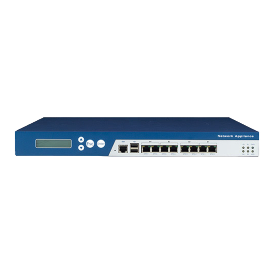
Page 17: Getting To Know The Nsa 3130
It indicates the status of the hard drive. LAN/Bypass Status LEDs They indicate the status of the LAN/Bypass. Copper LAN Ports They are used to connect LAN network devices. Copyright © 2012 NEXCOM International Co., Ltd. All Rights Reserved. NSA 3130 User Manual... -
Page 18: Rear Panel
Press the switch to power on or power off the system. Expansion Slot It is used to install a PCI Express x8 slot. VGA Port It is used to connect an analog VGA monitor. Copyright © 2012 NEXCOM International Co., Ltd. All Rights Reserved. NSA 3130 User Manual... -
Page 19: Chapter 2: Jumpers And Connectors
Ground yourself before touching any Use correct screws and do not over tighten screws. internal components, by touching a metal object. Static electricity can damage many of the electronic Copyright © 2012 NEXCOM International Co., Ltd. All Rights Reserved. NSA 3130 User Manual... -
Page 20: Jumper Settings
Refer to the illustrations below for examples of what the 2-pin and 3-pin jumpers look like when they are short (on) and open (off). Two-Pin Jumpers: Open (Left) and Short (Right) Copyright © 2012 NEXCOM International Co., Ltd. All Rights Reserved. NSA 3130 User Manual... -
Page 21: Locations Of The Jumpers And
The figure on the right is the NSB 3130 main board which is the main board used in the NSA 3130 system. It shows the locations of the jumpers and con- nectors. Copyright © 2012 NEXCOM International Co., Ltd. All Rights Reserved. NSA 3130 User Manual... -
Page 22: Jumpers
Pin Definition Pin Setting Pin Definition 1-2 On 1-2 On ATX Mode 3VSB 2-3 On GPIO24 2-3 On AT Mode AT_ATX_Select 2-3 ON Default 2-3 ON Default Copyright © 2012 NEXCOM International Co., Ltd. All Rights Reserved. NSA 3130 User Manual... -
Page 23: Connector Pin Definitions
Green 1G and Green Blinking Activity Always Lighted 10/100MB Yellow No Activity No link B1-B4 Yellow Definition Definition TX+0 TX-2 TX-0 TX-1 TX+1 TX+3 TX+2 TX-3 Copyright © 2012 NEXCOM International Co., Ltd. All Rights Reserved. NSA 3130 User Manual... -
Page 24: Rj45 Type Console Port (Lan1) (Rs232 Only)
RJ45 Type Console Port (LAN1) (RS232 Only) Connector Size: Dual USB port Connector Size: RJ45 port Definition Definition Definition Definition SP_RTS1_R SP_DTR1_R USB0- USB1- SP_TXD1_R USB0+ USB1+ SP_DCD1_R SP_RXD1_R SP_DSR1_R SP_CTS1_CON Copyright © 2012 NEXCOM International Co., Ltd. All Rights Reserved. NSA 3130 User Manual... -
Page 25: Gpi12 Software Button (Sw1)
GPI12 Software Button (SW1) Connector Size: 2-pin jack Definition RW_SW_RST Copyright © 2012 NEXCOM International Co., Ltd. All Rights Reserved. NSA 3130 User Manual... -
Page 26: Internal Connector
Connector size: 1x2 2-pin header, 2.54 mm pitch Signal PCH_SYS_ RESET_N_R Definition Definition GREEN Power Button (J7) BLUE Connector Size: 1X2 2-pin header, 2.54mm pitch VCC5 VGADATA Signal HSYNC VSYNC VGACLK PCH_PWRBTN_N Copyright © 2012 NEXCOM International Co., Ltd. All Rights Reserved. NSA 3130 User Manual... - Page 27 Connector Size: 2x5 10-pin box header, 2.0 mm pitch Definition Definition Definition Definition VCC5 VCC5 SP_DCD2 SP_RXD2 KB_DATA LM_DATA SP_TXD2 SP_DTR2 KB_CLK LM_CLK COM2_GND SP_DSR2 SP_RTS2 SP_CTS2 SP_RI2 COM2_GND Copyright © 2012 NEXCOM International Co., Ltd. All Rights Reserved. NSA 3130 User Manual...
- Page 28 Connector Size: 2X13 26-pin boxed header, 2.0mm pitch Description Description LPT_STB#R LPT_AFD#R LPT_PDR0 LPT_ERR#R LPT_PDR1 LPT_INIT#R Definition LPT_PDR2 LPT_SLIN#R LPT_PDR3 TXP0 LPT_PDR4 TXN0 LPT_PDR5 LPT_PDR6 RXN0 LPT_PDR7 RXP0 LPT_ACK#R LPT_BUSY LPT_PE LPT_SLCT Copyright © 2012 NEXCOM International Co., Ltd. All Rights Reserved. NSA 3130 User Manual...
- Page 29 Connector Size: 2x5 10-pin box header, 2.0 mm pitch System Fan Connector Size: 3-pin Wafer, 2.54 mm pitch Definition Definition VCC5 Definition SIO_GPIO10 SIO_GPIO14 +12V SIO_GPIO11 SIO_GPIO15 SENSE SIO_GPIO12 SIO_GPIO16 SIO_GPIO13 SIO_GPIO17 Copyright © 2012 NEXCOM International Co., Ltd. All Rights Reserved. NSA 3130 User Manual...
- Page 30 USB JST 2.00mm (J13) Power Connector (J14) Connector Size: 1X6 = 6-Pin Connector Size: 1X4 = 4-pin Definition Definition Definition P5V_USB_P23 USB2- VCC12 USB2+ USB3- USB3+ USB23GND VCC5 Copyright © 2012 NEXCOM International Co., Ltd. All Rights Reserved. NSA 3130 User Manual...
- Page 31 DIMM 1 = Channel A • Always populate DIMM1 first. The system will not SIO_GP04 SIO_GP76 boot when the first module is installed in DIMM2. SIO_GP05 SIO_GP77 Copyright © 2012 NEXCOM International Co., Ltd. All Rights Reserved. NSA 3130 User Manual...
- Page 32 SDIOR# SDIOW# HDIRQ14 CF_SEL# IDERST# SIORDY SDREQ SDDACK# Definition Definition IDEACTP# DIAG# SDD3A SDD8A SDD9A SDD4A SDD5A SDD10A SDD6A SDD7A SDCS#1 SDA2A SDA1A SDA0A SDD0A SDD1A Copyright © 2012 NEXCOM International Co., Ltd. All Rights Reserved. NSA 3130 User Manual...
-
Page 33: Block Diagram
Block Diagram NSA 3130 Copyright © 2012 NEXCOM International Co., Ltd. All Rights Reserved. NSA 3130 User Manual... -
Page 34: Chapter 3: System Setup
Remove the heat sink to access the CPU socket. The dots denote the locations of the screws. Lift up the cover then remove it from the chassis. Copyright © 2012 NEXCOM International Co., Ltd. All Rights Reserved. NSA 3130 User Manual... - Page 35 Unlock the socket by pushing the load lever down, Lift the load lever. moving it sideways until it is released from the retention tab. Copyright © 2012 NEXCOM International Co., Ltd. All Rights Reserved. NSA 3130 User Manual...
- Page 36 Lift the load plate. Position the CPU above the socket by using a suction tube. Copyright © 2012 NEXCOM International Co., Ltd. All Rights Reserved. NSA 3130 User Manual...
- Page 37 Do not force the CPU into the socket. Forcing the CPU into the socket may bend the pins and damage the CPU. Copyright © 2012 NEXCOM International Co., Ltd. All Rights Reserved. NSA 3130 User Manual...
- Page 38 When you later place the heat sink on top of the CPU, the compound will disperse evenly. Copyright © 2012 NEXCOM International Co., Ltd. All Rights Reserved. NSA 3130 User Manual...
- Page 39 Align the mounting screws of the heat sink with the mounting holes on the board. Tighten the screws to secure the heat sink in place. Copyright © 2012 NEXCOM International Co., Ltd. All Rights Reserved. NSA 3130 User Manual...
-
Page 40: Installing Adimm
DIMM2. Push the ejector tabs which are at the ends of the socket outward. This indicates that the socket is unlocked. Copyright © 2012 NEXCOM International Co., Ltd. All Rights Reserved. NSA 3130 User Manual... - Page 41 The ejector tabs at the ends of the socket will automatically snap into the locked position to hold the module in place. Copyright © 2012 NEXCOM International Co., Ltd. All Rights Reserved. NSA 3130 User Manual...
-
Page 42: Installing Asata Hard Drive
Secure the SATA to a HDD Bay by fixing the mounting screws around the HDD Bracket. Copyright © 2012 NEXCOM International Co., Ltd. All Rights Reserved. NSA 3130 User Manual... - Page 43 SATA drive with the mounting holes on the drive bay. Use the provided mounting screws to secure the SATA drive in place. Copyright © 2012 NEXCOM International Co., Ltd. All Rights Reserved. NSA 3130 User Manual...
- Page 44 Use the provided and the other end to the board. mounting screws to secure the drive bay in place. SATA Data Cable Mounting Screw Copyright © 2012 NEXCOM International Co., Ltd. All Rights Reserved. NSA 3130 User Manual...
- Page 45 Locate the SATA power connector on the SATA drive, and connect the SATA power cable from the power supply to the SATA drive. SATA Power Cable Copyright © 2012 NEXCOM International Co., Ltd. All Rights Reserved. NSA 3130 User Manual...
-
Page 46: Installing Asata Dom
Installing a SATA DOM Install the provided mounting stud as shown in the illustration below. Locate for the SATA connector on the board. SATA Connector SATA Connector Mounting Stud Copyright © 2012 NEXCOM International Co., Ltd. All Rights Reserved. NSA 3130 User Manual... - Page 47 Secure the SATA DOM with the provided mounting screw then connect the power cable to the power connector on the board. Power Power Cable Cable SATA SATA DOM SATA DOM (Solder Side) Copyright © 2012 NEXCOM International Co., Ltd. All Rights Reserved. NSA 3130 User Manual...
-
Page 48: Installing A Compactflash Card
Insert the card until it is Note: You can’t use the CompactFlash and completely seated in the socket. CFast cards at the same time. Locate the CompactFlash socket on the board. Copyright © 2012 NEXCOM International Co., Ltd. All Rights Reserved. NSA 3130 User Manual... - Page 49 Place a protective cover on the inserted CompactFlash Close the protective cover completely. card, lightly pulling the elastic side to fit two holes on the socket. Elastic Side Copyright © 2012 NEXCOM International Co., Ltd. All Rights Reserved. NSA 3130 User Manual...
-
Page 50: Installing Acf Ast Card
Insert the card until it is completely seated in CFast cards at the same time. the socket. Locate the CFast socket on the board. Copyright © 2012 NEXCOM International Co., Ltd. All Rights Reserved. NSA 3130 User Manual... -
Page 51: Installing Apci Express Card
Installing a PCI Express Card Remove the mounting screws that secure the L-shaped The PCI Express x8 slot is attached on an L-shaped bracket to the chassis. bracket. Copyright © 2012 NEXCOM International Co., Ltd. All Rights Reserved. NSA 3130 User Manual... - Page 52 Remove the slot cover’s mounting screw. Align the PCI Express card with the PCI Express slot then push it firmly until it is completely seated in the slot. Copyright © 2012 NEXCOM International Co., Ltd. All Rights Reserved. NSA 3130 User Manual...
- Page 53 Secure the card with the screw you removed in step 3. Install the bracket back into the chassis then secure the bracket with the mounting screws you removed in step 2. Copyright © 2012 NEXCOM International Co., Ltd. All Rights Reserved. NSA 3130 User Manual...
-
Page 54: Rackmount Bracket Kit (Optional)
Give special attention to the orientation of the rack ear. Secure the rack ear with mounting screws. Repeat step 3 to secure the other rack ear. Copyright © 2012 NEXCOM International Co., Ltd. All Rights Reserved. NSA 3130 User Manual... - Page 55 On one side of the rack, attach 3 nuts each at the front and back. Repeat this to the other side of the rack. Use the provided mounting screws to secure the server in the rack cabinet. Copyright © 2012 NEXCOM International Co., Ltd. All Rights Reserved. NSA 3130 User Manual...
-
Page 56: Chapter 4: Bios Setup
CMOS RAM, whenever the CMOS RAM has lost • Video display type and display options power, or the system features need to be changed. Copyright © 2012 NEXCOM International Co., Ltd. All Rights Reserved. NSA 3130 User Manual... -
Page 57: Default Configuration
Setup is to power on the computer and wait for the following message during the POST: TO ENTER SETUP BEFORE BOOT PRESS <CTRL-ALT-ESC> Press the <Del> key to enter Setup: Copyright © 2012 NEXCOM International Co., Ltd. All Rights Reserved. NSA 3130 User Manual... - Page 58 To display the submenu, move the highlight to that field and press <Enter>. Copyright © 2012 NEXCOM International Co., Ltd. All Rights Reserved. NSA 3130 User Manual...
-
Page 59: Bios Setup Utility
Day displays a day, from Sunday to Saturday. Month displays the month, from January to December. Date displays the date, from 1 to 31. Year displays the year, from 1980 to 2099. Copyright © 2012 NEXCOM International Co., Ltd. All Rights Reserved. NSA 3130 User Manual... -
Page 60: Advanced
This item is used to enable or disable 64bit capable Devices to be Decoded in Above 4G Address Space (only if System Supports 64bit PCI Decoding). Copyright © 2012 NEXCOM International Co., Ltd. All Rights Reserved. NSA 3130 User Manual... - Page 61 Ordering. Extended Tag If ENABLED allows Device to use 8-bit Tag field as a requester. No Snoop Enables or Disables PCI Express Device No Snoop option. Copyright © 2012 NEXCOM International Co., Ltd. All Rights Reserved. NSA 3130 User Manual...
- Page 62 Sleep State). This option may be not effective with some ACPI Sleep State Select the highest ACPI sleep state the system will enter, when the SUSPEND button is pressed. Copyright © 2012 NEXCOM International Co., Ltd. All Rights Reserved. NSA 3130 User Manual...
- Page 63 Disabled, only one thread per enabled core is enabled. SATA Mode Selection There are several options for your selection: (1) IDE Mode, (2) AHCI Mode and (3) RAID Mode. Copyright © 2012 NEXCOM International Co., Ltd. All Rights Reserved. NSA 3130 User Manual...
- Page 64 This section is used to configure the Software Feature This section provides Platform Thermal Configuration Mask settings. options. RAIDO This section is used to enable or disable RAIDO feature. Copyright © 2012 NEXCOM International Co., Ltd. All Rights Reserved. NSA 3130 User Manual...
- Page 65 BWG’s Thermal Reporting for Thermal Management settings. Set to Disabled for manual configuration. ME SMBus Thermal Reporting Enable/Disable ME SMBus Thermal Reporting Configuration. Copyright © 2012 NEXCOM International Co., Ltd. All Rights Reserved. NSA 3130 User Manual...
- Page 66 This section is used to enable or disable Me FW Image Technology BIOS Extension. (Note: iAMT H/W is always Re-Flash function. enabled. This option just controls the BIOS extension execution.) Copyright © 2012 NEXCOM International Co., Ltd. All Rights Reserved. NSA 3130 User Manual...
- Page 67 EHCI driver. Device Reset Timeout USB mass storage device Start Unit command timeout. Options are: 10 sec / 20 sec / 30 sec / 40 sec. Copyright © 2012 NEXCOM International Co., Ltd. All Rights Reserved. NSA 3130 User Manual...
- Page 68 Floppy Disk Controller Serial Port This item enables or disables the Floppy Disk Controller. This item section is used to enable or disable Serial Port (COM). Copyright © 2012 NEXCOM International Co., Ltd. All Rights Reserved. NSA 3130 User Manual...
- Page 69 Serial Port Parallel Port This item section is used to enable or disable Serial Port This item is used to enable or disable Parallel Port (COM). (LPT/LPTE). Copyright © 2012 NEXCOM International Co., Ltd. All Rights Reserved. NSA 3130 User Manual...
- Page 70 This section is used to configure the Serial Port Console events such as the temperature, fan speed and voltages. Redirection settings. Console Redirection This item is used to enable or disable Console Redirection. Copyright © 2012 NEXCOM International Co., Ltd. All Rights Reserved. NSA 3130 User Manual...
- Page 71 Server OS through a serial port. Terminal Type VT-UTF8 is the preferred terminal type for out-of-band management. The next best choice is VT100+ and then VT100. Copyright © 2012 NEXCOM International Co., Ltd. All Rights Reserved. NSA 3130 User Manual...
- Page 72 This section enables Watchdog Timer operation for ICC. If enabled, Watchdog Timer will be started after ICC-related changes. This timer detects platform instability caused by wrong clock settings. Copyright © 2012 NEXCOM International Co., Ltd. All Rights Reserved. NSA 3130 User Manual...
- Page 73 This section is used to configure the CPU PPM settings. This section is used to configure the Switchable Graphics settings. EIST This item enables or disables Intel SpeedStep. Copyright © 2012 NEXCOM International Co., Ltd. All Rights Reserved. NSA 3130 User Manual...
-
Page 74: Boot
NumLock on wherein the function of the numeric keypad is the number keys. When set to Off, the function of the numeric keypad is the arrow keys. Copyright © 2012 NEXCOM International Co., Ltd. All Rights Reserved. NSA 3130 User Manual... - Page 75 CSM Parameters Launch CSM The option controls of CSM will be launched. Copyright © 2012 NEXCOM International Co., Ltd. All Rights Reserved. NSA 3130 User Manual...
-
Page 76: Chipset
This section is used to configure the system based on the specific features of the chipset. Setting incorrect field values may cause the system to malfunction. PCH-IO Configuration System Agent (SA) Configuration Copyright © 2012 NEXCOM International Co., Ltd. All Rights Reserved. NSA 3130 User Manual... - Page 77 PCI Express Root Port This item controls the PCI Express Root Port. PCI Express Clock Gat This item enables or disables PCI Express Clock Gating for each root port. Copyright © 2012 NEXCOM International Co., Ltd. All Rights Reserved. NSA 3130 User Manual...
- Page 78 This item controls the USB EHCI (USB 2.0) functions. One VT-d EHCI controller must always be enabled. Use this to check if VT-d function is enabled on MCH. Copyright © 2012 NEXCOM International Co., Ltd. All Rights Reserved. NSA 3130 User Manual...
- Page 79 This item selects the Video Device which will be activated (14-31). during POST. This has no effect if external graphics present. Secondary boot display selection will appear based on your selection. Copyright © 2012 NEXCOM International Co., Ltd. All Rights Reserved. NSA 3130 User Manual...
- Page 80 This section is used to configure the NB PCIe settings. DMI Vc1 Control PlEG0 – Gen X This item enables or disables DMI Vc1. This item configures PEG0 B0:D1:f0 Gen1-Gen3. Copyright © 2012 NEXCOM International Co., Ltd. All Rights Reserved. NSA 3130 User Manual...
- Page 81 This section is used to configure the Memory Thermal settings. DIMM Profile This item selects DIMM timing profile that should be used. Memory Thermal Manage This item enables or disables the Memory Thermal Management. Copyright © 2012 NEXCOM International Co., Ltd. All Rights Reserved. NSA 3130 User Manual...
- Page 82 GT-Power Management Control RC6 (Render Standby) Use this to check if render standby support is enabled. Copyright © 2012 NEXCOM International Co., Ltd. All Rights Reserved. NSA 3130 User Manual...
-
Page 83: Security
1. Select the Change User Password field then press <Enter>. 2. Type your password in the dialog box then press <Enter>. You are limited to eight letters/numbers. Copyright © 2012 NEXCOM International Co., Ltd. All Rights Reserved. NSA 3130 User Manual... - Page 84 The BIOS checks for the user password whenever accessing the Setup utility. Always The BIOS checks for the user password when accessing the Setup utility and booting the system. Copyright © 2012 NEXCOM International Co., Ltd. All Rights Reserved. NSA 3130 User Manual...
-
Page 85: Save & Exit
To save the changes and exit the Setup utility, select this field then press <Enter>. A dialog box will appear. Confirm by selecting OK. You can also press <F10> to save and exit Setup. Copyright © 2012 NEXCOM International Co., Ltd. All Rights Reserved. NSA 3130 User Manual... - Page 86 You can also press <ESC> to exit without saving the You can also press <F7> to discard the changes. changes. Copyright © 2012 NEXCOM International Co., Ltd. All Rights Reserved. NSA 3130 User Manual...
- Page 87 <Enter>. A dialog box will appear. Confirm by selecting OK. selecting OK. You can also press <F9> to load optimal default values. You can also press <F9> to load failsafe default values. Copyright © 2012 NEXCOM International Co., Ltd. All Rights Reserved. NSA 3130 User Manual...
-
Page 88: Appendix A: Watchdog Timer
Appendix A: Watchdog Timer Watchdog Timer Setting CRFC6 (Default 0x00) NSA 3130 features a watchdog timer that resets the CPU or Watchdog Timer Time-out Value generates an interrupt if the processor stops operating for any reason. This feature ensures system reliability in Writing a non-zero value to this register causes the counter to industrial standalone or unmanned environments. - Page 89 Copyright © 2012 NEXCOM International Co., Ltd. All Rights Reserved. NSA 3130 User Manual...
-
Page 90: Appendix B: Gpi/O Programming Guide
Appendix B: GPI/O Programming Guide This appendix provides definitions for the four GPI/O pins on NSA 3130. GPI/O (General Purpose Input/Output) pins are provided for custom system design. The pin programmed as input mode (GPI) or output mode (GPO) depends on the configuration. - Page 91 Copyright © 2012 NEXCOM International Co., Ltd. All Rights Reserved. NSA 3130 User Manual...
- Page 92 Read GPI12 Sample Code mov dx,48Dh in al,dx and al,10h ;now al (bit4) is GPIO12 value. Copyright © 2012 NEXCOM International Co., Ltd. All Rights Reserved. NSA 3130 User Manual...
-
Page 93: Appendix C: Bypass Specifications
Appendix C: Bypass Specifications Bypass Control Function NSA 3130 provides LAN bypass functionality to ensure that data can still pass through the device, even when it is BCSR - Bypass Control Status Register = 0XF3 powered off. This feature helps ensure the continuous flow of data through the device in the event of a hardware failure. - Page 94 Bit 3: Segment 4 (facing the front panel, the fourth from the right is the 4th Bypass) 0 - Set segment bypass Disable when power off 1 - Set segment bypass Enable when power off Copyright © 2012 NEXCOM International Co., Ltd. All Rights Reserved. NSA 3130 User Manual...
-
Page 95: Appendix D: Power Consumption
Appendix D: Power Consumption Power Consumption Copyright © 2012 NEXCOM International Co., Ltd. All Rights Reserved. NSA 3130 User Manual... - Page 96 Power Supply Must Consumed Watts and Currents Copyright © 2012 NEXCOM International Co., Ltd. All Rights Reserved. NSA 3130 User Manual...
Need help?
Do you have a question about the NSA 3130 and is the answer not in the manual?
Questions and answers