
Related Manuals for Nexcom NSA 5130


Summary of Contents for Nexcom NSA 5130
- Page 1 NEXCOM International Co., Ltd. Network and Communication Solutions Network Security Appliance NSA 5130 User Manual NEXCOM International Co., Ltd. www.nexcom.com Published April 2014...
-
Page 2: Table Of Contents
Hardware Specifications ................2 LAN5 Port ..................18 NSA 5130 System .................2 LAN6 Port ..................18 Main Board (NSB 5130) ................4 LAN7 Port ..................19 LAN8 Port ..................19 VGA Connector ................20 Copyright © 2011 NEXCOM International Co., Ltd. All Rights Reserved. NSA 5130 User Manual... - Page 3 Installing a CompactFlash Card .............44 Installing a 3.5” SATA Hard Drive ............46 Installing a PCI Express x8 Card .............49 Replacing the LAN Module ..............51 Rackmount Bracket Kit (optional) ............55 Copyright © 2011 NEXCOM International Co., Ltd. All Rights Reserved. NSA 5130 User Manual...
-
Page 4: Preface
Acknowledgements The product(s) described in this manual complies with all applicable Euro- NSA 5130 is a trademark of NEXCOM International Co., Ltd. All other pean Union (CE) directives if it has a CE marking. For computer systems to product names mentioned herein are registered trademarks of their respec- remain CE compliant, only CE-compliant parts may be used. -
Page 5: Rohs Compliance
0.1% or 1,000ppm, and Polybrominated diphenyl Ethers (PBDE) < 0.1% or 1,000ppm. In order to meet the RoHS compliant directives, NEXCOM has established an engineering and manufacturing task force in to implement the introduction of green products. The task force will ensure that we follow the standard... -
Page 6: Warranty And Rma
? Replace with 3rd party products if needed. the RMA number apply process. ? If RMA goods can not be repaired, NEXCOM will return it to the cus- tomer without any charge. ? Customers can send back the faulty products with or without acces- sories (manuals, cable, etc.) and any components from the card, such as... -
Page 7: Safety Information
There is a danger of explosion if battery is incorrectly replaced. Replace only with the same or equivalent type recommended by the manufactur- er. Discard used batteries according to the manufacturer’s instructions. Copyright © 2011 NEXCOM International Co., Ltd. All Rights Reserved. NSA 5130 User Manual... -
Page 8: Safety Precautions
11. All cautions and warnings on the equipment should be noted. 19. The computer is provided with CD drives that comply with the ap- propriate safety standards including IEC 60825. viii Copyright © 2011 NEXCOM International Co., Ltd. All Rights Reserved. NSA 5130 User Manual... -
Page 9: Technical Support And Assistance
Technical Support and Assistance Conventions Used in this Manual Warning: Information about certain situations, which if not 1. For the most updated information of NEXCOM products, visit NEX- observed, can cause personal injury. This will prevent injury to COM’s website at www.nexcom.com. -
Page 10: Global Service Contact Information
Tel: +86-21-5278-5868 16F, No.250, Sec. 2, Chongde Rd., Fax: +86-21-3251-6358 Beitun Dist., Taichung City 406, R.O.C. Email: sales@nexcom.cn Tel: +886-4-2249-1179 www.nexcom.cn Fax: +886-4-2249-1172 Email: sales@nexcom.com.tw www.nexcom.com.tw Copyright © 2011 NEXCOM International Co., Ltd. All Rights Reserved. NSA 5130 User Manual... -
Page 11: United Kingdom
Fax: +44-1908-262042 Email: sales.uk@nexcom.eu Chengdu Office www.nexcom.eu 9F, Shuxiangxie, Xuefu Garden, No.12 Section 1, South Yihuan Rd., Chengdu, 610061, China Tel: +86-28-8523-0186 Fax: +86-28-8523-0186 Email: sales@nexcom.cn www.nexcom.cn Copyright © 2011 NEXCOM International Co., Ltd. All Rights Reserved. NSA 5130 User Manual... -
Page 12: Package Contents
Preface Package Contents Before continuing, verify that the NSA 5130 package that you received is complete. Your package should have all the items listed in the following table. Item Name Description 19S00513000X0 NSA5130 ASSY 5044440031X00 RUBBER FOOT KANG YANG:RF20-5-4P 19.8x18x5.0mm... -
Page 13: Ordering Information
10SK0538003X0 INTEL NH82580EB PCIe x8 4 SFP None None All Slot ® NSK5399-F2 10SK0539900X0 INTEL ® L82599ES PCIe x8 2 SFP None None All Slot xiii Copyright © 2011 NEXCOM International Co., Ltd. All Rights Reserved. NSA 5130 User Manual... -
Page 14: Chapter 1: Product Introduction
2nd Generation Core™ Processors • 1x internal 3.5” HDD Bay / 2x 2.5” HDD Bay (optional) • 4x DDR3 1066/1333 Memory, up to 16GB • 1x PCIe x8 expansion Copyright © 2011 NEXCOM International Co., Ltd. All Rights Reserved. NSA 5130 User Manual... -
Page 15: Hardware Specifications
• 4 x 240-pin DDR3 1066/1333MHz DIMM sockets, up to 16GB ECC/ non-ECC SDRAM • Intel 82583V LAN chip, LAN Bypass: 4 pairs, 10/100/1000 link speed ® Copyright © 2011 NEXCOM International Co., Ltd. All Rights Reserved. NSA 5130 User Manual... - Page 16 - Frequency: 5 - 500 Hz • UL - Acceleration: 0.3g • LVD • Random vibration test (packing) - Frequency: 1 - 200 Hz - Acceleration: 1.15g Copyright © 2011 NEXCOM International Co., Ltd. All Rights Reserved. NSA 5130 User Manual...
-
Page 17: Main Board (Nsb 5130)
- ETH1 (the left side of LAN) • LAN module (optional) - One PCIe x8 connected to CPU PCIe bus - Supports Nexcom NSK53xx series modules Copyright © 2011 NEXCOM International Co., Ltd. All Rights Reserved. NSA 5130 User Manual... - Page 18 - 1x PCIe x16 slot for a x8 slot on the riser card - 1x VGA port BIOS - 2x USB ports • Flash ROM - 64MB (SPI) • Type - AMI BIOS Copyright © 2011 NEXCOM International Co., Ltd. All Rights Reserved. NSA 5130 User Manual...
- Page 19 C - 75 • Relative Humidity - 10%-90% non-condensing • EMI/EMC - CE/FCC Class A • ESD - 2/4KV contact discharge, 2/4/8KV air discharge, Criteria B Copyright © 2011 NEXCOM International Co., Ltd. All Rights Reserved. NSA 5130 User Manual...
-
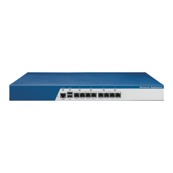
Page 20: Getting To Know Nsa 5130
LAN/Bypass Status LEDs Used to connect LAN network devices. Indicates the status of the LAN/Bypass (F3/F7 bit2 to bit5). USB Ports Used to connect USB 2.0/1.1 devices. Copyright © 2011 NEXCOM International Co., Ltd. All Rights Reserved. NSA 5130 User Manual... -
Page 21: Rear Panel
Rear Panel Expansion slot Power switch Power On/Off Switch Press to power-on or power-off the system. Expansion Slot Used to install a PCI Express x8 card. Copyright © 2011 NEXCOM International Co., Ltd. All Rights Reserved. NSA 5130 User Manual... -
Page 22: Chapter 2: Jumpers And Connectors
This chapter describes how to set the jumpers on the motherboard. Note tronic components. Humid environment tend to have less static electric- that the following procedures are generic for NSA 5130. ity than dry environments. A grounding strap is warranted whenever danger of static electricity exists. -
Page 23: Jumper Settings
(on) and open (off). Two-Pin Jumpers: Open (Left) and Short (Right) Three-Pin Jumpers: Pins 1 and 2 Are Short Copyright © 2011 NEXCOM International Co., Ltd. All Rights Reserved. NSA 5130 User Manual... -
Page 24: Locations Of The Jumpers And Connectors
Locations of the Jumpers and Connectors NSB 5130 The figure on the right is the NSB 5130 main board which is the main board used in the NSA 5130 system. It shows the locations of the jumpers and connec- tors. -
Page 25: Jumpers
1-2 On Normal 1-2 On Normal 2-3 On CMOS Clear 2-3 On ME Force Update 1-2 On: default 1-2 On: default Definition Definition ICH_RTCRST_N GPIO24 Battery GND Copyright © 2011 NEXCOM International Co., Ltd. All Rights Reserved. NSA 5130 User Manual... - Page 26 Definition 1-2 On RTS to CTS 1-2 On 2-3 On Normal 2-3 On 1-2 On: default 2-3 On: default Definition Definition SP_RTS1_R 3VSB AT_ATX_SELECT SP_CTS1_R SP_CTS1_CON Copyright © 2011 NEXCOM International Co., Ltd. All Rights Reserved. NSA 5130 User Manual...
-
Page 27: Connectors Pin Definitions
Connector location: CN1 GPIO (F6 bit0) GPIO (F6 bit1) Definition Definition Status LED Color USB0- USB1- Green USB0+ USB1+ Yellow F6 0 Yellow F6 1 Yellow Copyright © 2011 NEXCOM International Co., Ltd. All Rights Reserved. NSA 5130 User Manual... -
Page 28: Rj45 Type Console Port
Software Push Button Connector type: RJ45 port Connector type: 2-pin jack Connector location: LAN1 Connector location: SW1 Definition Definition Definition SP_RTS1_R SP_DTR1_R SP_TXD1_R RW_SW_RST SP_DCD1_R SP_RXD1_R SP_DSR1_R SP_CTS1_CON Copyright © 2011 NEXCOM International Co., Ltd. All Rights Reserved. NSA 5130 User Manual... -
Page 29: Lan1 Port
LAN1_TXP0_CON LAN1_TXN0_CON LAN2_TXP0_CON LAN2_TXN0_CON LAN1_TXP1_CON LAN1_TXP2_CON LAN2_TXP1_CON LAN2_TXP2_CON LAN1_TXN2_CON LAN1_TXN1_CON LAN2_TXN2_CON LAN2_TXN1_CON LAN1_TXP3_CON LAN1_TXN3_CON LAN2_TXP3_CON LAN2_TXN3_CON LAN1_LED_LINK100# LAN1_LED_LINK1G# LAN2_LED_LINK100# LAN2_LED_LINK1G# LAN1_LED_ACT# LAN1_ACTPW LAN2_LED_ACT# LAN2_ACTPW GND_IO GND_IO Copyright © 2011 NEXCOM International Co., Ltd. All Rights Reserved. NSA 5130 User Manual... -
Page 30: Lan3 Port
LAN3_TXP0_CON LAN3_TXN0_CON LAN4_TXP0_CON LAN4_TXN0_CON LAN3_TXP1_CON LAN3_TXP2_CON LAN4_TXP1_CON LAN4_TXP2_CON LAN3_TXN2_CON LAN3_TXN1_CON LAN4_TXN2_CON LAN4_TXN1_CON LAN3_TXP3_CON LAN3_TXN3_CON LAN4_TXP3_CON LAN4_TXN3_CON LAN3_LED_LINK100# LAN3_LED_LINK1G# LAN4_LED_LINK100# LAN4_LED_LINK1G# LAN3_LED_ACT# LAN3_ACTPW LAN4_LED_ACT# LAN4_ACTPW GND_IO GND_IO Copyright © 2011 NEXCOM International Co., Ltd. All Rights Reserved. NSA 5130 User Manual... -
Page 31: Lan5 Port
LAN5_TXP0_CON LAN5_TXN0_CON LAN6_TXP0_CON LAN6_TXN0_CON LAN5_TXP1_CON LAN5_TXP2_CON LAN6_TXP1_CON LAN6_TXP2_CON LAN5_TXN2_CON LAN5_TXN1_CON LAN6_TXN2_CON LAN6_TXN1_CON LAN5_TXP3_CON LAN5_TXN3_CON LAN6_TXP3_CON LAN6_TXN3_CON LAN5_LED_LINK100# LAN5_LED_LINK1G# LAN6_LED_LINK100# LAN6_LED_LINK1G# LAN5_LED_ACT# LAN5_ACTPW LAN6_LED_ACT# LAN6_ACTPW GND_IO GND_IO Copyright © 2011 NEXCOM International Co., Ltd. All Rights Reserved. NSA 5130 User Manual... -
Page 32: Lan7 Port
LAN7_TXP0_CON LAN7_TXN0_CON LAN8_TXP0_CON LAN8_TXN0_CON LAN7_TXP1_CON LAN7_TXP2_CON LAN8_TXP1_CON LAN8_TXP2_CON LAN7_TXN2_CON LAN7_TXN1_CON LAN8_TXN2_CON LAN8_TXN1_CON LAN7_TXP3_CON LAN7_TXN3_CON LAN8_TXP3_CON LAN8_TXN3_CON LAN7_LED_LINK100# LAN7_LED_LINK1G# LAN8_LED_LINK100# LAN8_LED_LINK1G# LAN7_LED_ACT# LAN1_ACTPW LAN8_LED_ACT# LAN8_ACTPW GND_IO GND_IO Copyright © 2011 NEXCOM International Co., Ltd. All Rights Reserved. NSA 5130 User Manual... -
Page 33: Vga Connector
Chapter 2: Jumpers and Connectors VGA Connector Connector type: 2x8 16-pin box header, 2.0 mm pitch Connector location: CN5 Definition Definition VGA_R_CON VGA_VCC VGA_G_CON VGA_B_CON VGA_I2CDAT_CON VGA_HSYNC_CON VGA_VSYNC_CON VGA_I2CCLK_CON Copyright © 2011 NEXCOM International Co., Ltd. All Rights Reserved. NSA 5130 User Manual... -
Page 34: Internal Connectors
Connector type: Standard Serial ATAII, 1.27mm Connector type: Standard Serial ATAII, 1.27mm Connector location: J12 Connector location: J11 Definition Definition SATA_TX2P SATA_TX1P SATA_TX2N SATA_TX1N SATA_RX2N SATA_RX1N SATA_RX2P SATA_RX1P Copyright © 2011 NEXCOM International Co., Ltd. All Rights Reserved. NSA 5130 User Manual... -
Page 35: Sata4 Port
SATA Power Connector Connector type: Standard Serial ATAII, 1.27mm Connector type: 1x4 4-pin header Connector location: J14 Connector location: J17 Definition VCC12 Definition VCC5 SATA_TX0P SATA_TX0N SATA_RX0N SATA_RX0P Copyright © 2011 NEXCOM International Co., Ltd. All Rights Reserved. NSA 5130 User Manual... -
Page 36: Sata Dom Power Connector
Connector type: 2x5 10-pin header, 2.0 mm Connector location: J13 Connector location: J9 Definition Definition Definition VCC5 VCC5 SIO_GP32 SIO_GP06 SIO_GP03 SIO_GP07 SIO_GP04 SIO_GP76 SIO_GP05 SIO_GP77 Copyright © 2011 NEXCOM International Co., Ltd. All Rights Reserved. NSA 5130 User Manual... -
Page 37: Com2 Connector
Connector type: 1x6 6-pin, 2.0 mm JST Connector location: CN3 Connector location: J16 Definition Definition Definition SP_DCD2 SP_RXD2 USB2- SP_TXD2 SP_DTR2 USB2+ COM2_GND SP_DSR2 USB3- SP_RTS2 SP_CTS2 USB3+ SP_RI2 COM2_GND Copyright © 2011 NEXCOM International Co., Ltd. All Rights Reserved. NSA 5130 User Manual... -
Page 38: Parallel Interface For Lcm Module
Connector location: CN2 Connector location: JP2 Definition Definition Definition KEY_PIN1 KEY_PIN2 LPT_SLIN#R LPT_RES KEY_PIN3 LPT_AFD#R LPT_INIT#R KEY_PIN4 LPT_PDR1 LPT_PDR0 LPT_PDR3 LPT_PDR2 LPT_PDR5 LPT_PDR4 LPT_PDR7 LPT_PDR6 LPT_PW VCC5 Copyright © 2011 NEXCOM International Co., Ltd. All Rights Reserved. NSA 5130 User Manual... -
Page 39: Hw Reset Button
Connector type: 1x2 2-pin header, 2.54 mm pitch Connector type: 1x2 2-pin header, 2.54 mm pitch Connector location: JP6 Connector location: J18 Definition Definition PCH_SYS_RESET_N_R PCH_PWRBTN_N Copyright © 2011 NEXCOM International Co., Ltd. All Rights Reserved. NSA 5130 User Manual... -
Page 40: Power Connector
Connector type: 1x6 6-pin header, 2.54 mm Connector location: CN6 Connector location: J10 Definition Definition Definition 3VSB VCC3_3 VCC3_3 VCC5 GAL_TCK VCC5 GAL_TDO ATXPWROK GAL_TDI GAL_TMS 5VSB VCC12 VCC3_3 SIO_PSON_N VCC5 VCC5 Copyright © 2011 NEXCOM International Co., Ltd. All Rights Reserved. NSA 5130 User Manual... -
Page 41: System Fan (Fan1)
Connector type: 1x3 3-pin Wafer, 2.54 mm pitch Connector type: 1x3 3-pin Wafer, 2.54 mm pitch Connector location: FAN1 Connector location: FAN2 Definition Definition VCC12 VCC12 FAN2 FAN3 Copyright © 2011 NEXCOM International Co., Ltd. All Rights Reserved. NSA 5130 User Manual... -
Page 42: Cpu Fan Connector
Connector type: 1x4 4-pin Wafer, 2.54 mm pitch Connector type: 1x4 4-pin Wafer, 2.54 mm pitch Connector location: FAN3 Connector location: FAN4 Definition Definition VCC12 VCC12 CPU_FAN FAN1 CPU_FANPWM AUX_FANPWM Copyright © 2011 NEXCOM International Co., Ltd. All Rights Reserved. NSA 5130 User Manual... -
Page 43: Pcie Slot
VCC3_3 VCC12 VCC12 PEG_SLOT_TX11P VCC3_3 3VSB PEG_SLOT_TX11N PLT_RST_BUF3_N PCIE_WAKE_L PEG_SLOT_RX11P VCC12 PEG_SLOT_RX11N PCIE_X16_CLK_1P PEG_SLOT_TX10P PCIE_X16_CLK_1N PEG_SLOT_TX15P PEG_SLOT_TX10N PEG_SLOT_TX15N PEG_SLOT_RX10P PEG_SLOT_RX15P PEG_SLOT_RX10N PEG_SLOT_RX15N PCIE16_PRSNT2_1 PEG_SLOT_TX9P PEG_SLOT_TX9N PEG_SLOT_RX9P Copyright © 2011 NEXCOM International Co., Ltd. All Rights Reserved. NSA 5130 User Manual... - Page 44 PEG_SLOT_TX7N PEG_SLOT_RX1P PEG_SLOT_RX7P PEG_SLOT_RX1N PEG_SLOT_RX7N PEG_SLOT_TX0P PEG_SLOT_TX6P PEG_SLOT_TX0N PEG_SLOT_TX6N PEG_SLOT_RX0P PEG_SLOT_RX6P PEG_SLOT_RX0N PCIE_X16_CLK_2P PEG_SLOT_RX6N PCIE_X16_CLK_2N PEG_SLOT_TX5P PEG_SLOT_TX5N PEG_SLOT_RX5P PEG_SLOT_RX5N PEG_SLOT_TX4P PEG_SLOT_TX4N PEG_SLOT_RX4P PEG_SLOT_RX4N PEG_SLOT_TX3P PEG_SLOT_TX3N PEG_SLOT_RX3P Copyright © 2011 NEXCOM International Co., Ltd. All Rights Reserved. NSA 5130 User Manual...
-
Page 45: Pcie Gold Finger (For Lan Module)
VCC3_3 WAKE_N PCIEX8_TX4P PCIEX8_RX4P VCC3_3 3VSB PCIEX8_TX4N PCIEX8_RX4N PCIE_X8_GF_CLK_P 3VSB PCIE_X8_GF_CLK_N 3VSB PCIEX8_TX5P PCIEX8_RX5P VCC3_3 USB_4P PCIEX8_TX5N PCIEX8_RX5N CLK_GF_33M USB_4N VCC3_3 VCC3_3 PCIEX8_TX6P PCIEX8_RX6P AUX_TEMP VCC3_3 Copyright © 2011 NEXCOM International Co., Ltd. All Rights Reserved. NSA 5130 User Manual... - Page 46 Chapter 2: Jumpers and Connectors Definition Definition PCIEX8_TX6N PCIEX8_RX6N PCIEX8_TX7P PCIEX8_RX7P PCIEX8_TX7N PCIEX8_RX7N Copyright © 2011 NEXCOM International Co., Ltd. All Rights Reserved. NSA 5130 User Manual...
-
Page 47: Block Diagram Of The Main Board
Ports x 2 LPC Bus VGA Chip LC4256V P56 ~ P61 SATA to IDE SATA DOM JMD330 SUPER I/O COM 2 ports NCT6776F PS/2 KB/MS GPIO CF card Copyright © 2011 NEXCOM International Co., Ltd. All Rights Reserved. NSA 5130 User Manual... -
Page 48: Chapter 3: System Setup
2. Slide the cover backward and then remove it from the chassis. chassis. Remove these screws and put them in a safe place for later use. Copyright © 2011 NEXCOM International Co., Ltd. All Rights Reserved. NSA 5130 User Manual... -
Page 49: Installing A Dimm
• When installing 2 modules for single channel configuration, populate DIMM1 and DIMM2 first. • When installing 2 modules for dual channel configuration, populate DIMM1 and DIMM3 first. Copyright © 2011 NEXCOM International Co., Ltd. All Rights Reserved. NSA 5130 User Manual... - Page 50 “key” on the socket. The key ensures the tomatically snap into the locked position to hold the module in place. module can be plugged into the socket in only one direction. Copyright © 2011 NEXCOM International Co., Ltd. All Rights Reserved. NSA 5130 User Manual...
-
Page 51: Installing The Cpu
• The CPU socket must not come in contact with anything other than the CPU. Avoid unnecessary exposure. Remove the protec- tive cap only when you are about to install the CPU. Copyright © 2011 NEXCOM International Co., Ltd. All Rights Reserved. NSA 5130 User Manual... - Page 52 (2) until it is released from the retention tab; then lift the load Lift the load lever up to the angle shown on the photo. lever up. Load lever Load lever Load plate Retention tab Copyright © 2011 NEXCOM International Co., Ltd. All Rights Reserved. NSA 5130 User Manual...
- Page 53 • Handle the CPU by its edges and avoid touching the pins. • The CPU will fit in only one orientation and can easily be in- serted without exerting any force. Copyright © 2011 NEXCOM International Co., Ltd. All Rights Reserved. NSA 5130 User Manual...
- Page 54 Retention Retention knob Do not force the CPU into the socket. Forcing the CPU into the socket may bend the pins and damage the CPU. Copyright © 2011 NEXCOM International Co., Ltd. All Rights Reserved. NSA 5130 User Manual...
- Page 55 When you later place the heat sink on top on the board. of the CPU, the compound will disperse evenly. Thermal compound on the CPU Mounting hole Copyright © 2011 NEXCOM International Co., Ltd. All Rights Reserved. NSA 5130 User Manual...
- Page 56 Chapter 3: System Setup 11. Tighten the screws to secure the heat sink in place. Heat sink Copyright © 2011 NEXCOM International Co., Ltd. All Rights Reserved. NSA 5130 User Manual...
-
Page 57: Installing A Compactflash Card
1. Locate for the CompactFlash socket on the board. 2. With the CompactFlash card’s label facing up, position the card to the socket. CompactFlash socket CompactFlash card Copyright © 2011 NEXCOM International Co., Ltd. All Rights Reserved. NSA 5130 User Manual... - Page 58 Chapter 3: System Setup 3. Insert the card until it is completely seated in the socket. Copyright © 2011 NEXCOM International Co., Ltd. All Rights Reserved. NSA 5130 User Manual...
-
Page 59: Installing A 3.5" Sata Hard Drive
Use the provided mounting screws to secure the SATA drive in place. SATA drive Drive bay Drive bay Mounting screw Mounting screw Mounting screw Copyright © 2011 NEXCOM International Co., Ltd. All Rights Reserved. NSA 5130 User Manual... - Page 60 3. Locate for the SATA connector and the SATA power connector on the 4. Locate for the SATA cable and the SATA power cable. SATA drive. SATA data cable SATA power connector SATA connector SATA power cable Copyright © 2011 NEXCOM International Co., Ltd. All Rights Reserved. NSA 5130 User Manual...
- Page 61 6. Place the drive into the chassis and then use the provided mounting screws to secure the drive bay in place. SATA data SATA power cable cable Mounting screw Copyright © 2011 NEXCOM International Co., Ltd. All Rights Reserved. NSA 5130 User Manual...
-
Page 62: Installing A Pci Express X8 Card
Remove the mounting screws that secure the L-shaped bracket to the chassis and then remove the bracket. Slot cover PCI Express x8 slot Riser card L-shaped bracket Copyright © 2011 NEXCOM International Co., Ltd. All Rights Reserved. NSA 5130 User Manual... - Page 63 Secure the card with the mounting screw you removed in step 2. Mounting screw PCI Express card PCI Express x8 slot Copyright © 2011 NEXCOM International Co., Ltd. All Rights Reserved. NSA 5130 User Manual...
-
Page 64: Replacing The Lan Module
1. Remove the mounting screws on the cover plate of the LAN module. Mounting screw LAN module Mounting screw Cover plate Mounting screw Only plug approved mini-GBIC module into the slot. Copyright © 2011 NEXCOM International Co., Ltd. All Rights Reserved. NSA 5130 User Manual... - Page 65 Mounting screw 4. Once all the mounting screws are removed, lay the chassis back down and unplug all the LED connectors behind the front panel. connector Copyright © 2011 NEXCOM International Co., Ltd. All Rights Reserved. NSA 5130 User Manual...
- Page 66 When removing, please handle the LAN module carefully by pulling it gently. Base plate Components on bottom Copyright © 2011 NEXCOM International Co., Ltd. All Rights Reserved. NSA 5130 User Manual...
- Page 67 LED connectors, and replace the cover plate and the chassis cover to finish. LAN module Pull gently Top view Copyright © 2011 NEXCOM International Co., Ltd. All Rights Reserved. NSA 5130 User Manual...
-
Page 68: Rackmount Bracket Kit (Optional)
3. Align the mounting holes on the rack ear with the mounting holes on the front panel. Give special attention to the orientation of the rack ear. Secure the rack ear with mounting screws. Rack ear Copyright © 2011 NEXCOM International Co., Ltd. All Rights Reserved. NSA 5130 User Manual... - Page 69 Chapter 3: System Setup 4. Repeat step 3 to secure the other rack ear. Rack ear Rack ear Copyright © 2011 NEXCOM International Co., Ltd. All Rights Reserved. NSA 5130 User Manual...
- Page 70 2. On one side of the rack, attach 3 nuts each at the front and back. Repeat this to the other side of the rack. Nuts Copyright © 2011 NEXCOM International Co., Ltd. All Rights Reserved. NSA 5130 User Manual...
- Page 71 Chapter 3: System Setup 4. Use the provided mounting screws to secure the server in the rack cabinet. Copyright © 2011 NEXCOM International Co., Ltd. All Rights Reserved. NSA 5130 User Manual...
-
Page 72: Chapter 4: Bios Setup
BIOS is updated in the future. options, and second, to make settings appropriate for the way you use the computer. To check for the latest updates and revisions, visit the NEXCOM Web site at www.nexcom.com.tw. When to Configure the BIOS... -
Page 73: Default Configuration
When “u“ appears on the left of a particular field, it indicates that a submenu which contains additional options are available for that field. To display the submenu, move the highlight to that field and press <Enter>. Copyright © 2011 NEXCOM International Co., Ltd. All Rights Reserved. NSA 5130 User Manual... -
Page 74: Bios Setup Utility
General Help Administrator Access Level Previous Values Optimized Defaults Save ESC: Exit Version 2.11.1210. Copyright (C) 2011 American Megatrends, Inc. BIOS Information Displays the detected BIOS information. Copyright © 2011 NEXCOM International Co., Ltd. All Rights Reserved. NSA 5130 User Manual... -
Page 75: Advanced
Previous Values Super IO Configuration Optimized Defaults H/W Monitor Save AMT Configuration ESC: Exit Serial Port Console Redirection Version 2.11.1210. Copyright (C) 2011 American Megatrends, Inc. Copyright © 2011 NEXCOM International Co., Ltd. All Rights Reserved. NSA 5130 User Manual... - Page 76 When this function is enabled, it allows generation of extended synchro- values for the PCI Latency Timer will reduce the effectiveness of the PCI nization patterns. bandwidth while higher values will improve it. Copyright © 2011 NEXCOM International Co., Ltd. All Rights Reserved. NSA 5130 User Manual...
- Page 77 Selects the highest ACPI sleep state the system will enter when the Sus- pend button is pressed. S1(POS) Enables the Power On Suspend function. S3(STR) Enables the Suspend to RAM function. Copyright © 2011 NEXCOM International Co., Ltd. All Rights Reserved. NSA 5130 User Manual...
- Page 78 General Help Previous Values Optimized Defaults Save ESC: Exit Version 1.24.1115. Copyright (C) 2008 American Megatrends, Inc. WHEA Support Enables or disables the Windows hardware error architecture. Copyright © 2011 NEXCOM International Co., Ltd. All Rights Reserved. NSA 5130 User Manual...
- Page 79 If you are using an operating system other than Windows, this problem may occur. To avoid this problem, enable this field to limit the return value to 3 or lesser than 3. Copyright © 2011 NEXCOM International Co., Ltd. All Rights Reserved. NSA 5130 User Manual...
-
Page 80: Network Configuration
Enables or disables the LAN module bypass mode after the system powers Bypass Mode After Power Off Enables or disables the LAN module bypass mode after the system powers off. Copyright © 2011 NEXCOM International Co., Ltd. All Rights Reserved. NSA 5130 User Manual... - Page 81 This option configures the Serial ATA drives in IDE mode. RAID This option enables the RAID function for Serial ATA drives. AHCI This option configures the Serial ATA drives in AHCI mode. Copyright © 2011 NEXCOM International Co., Ltd. All Rights Reserved. NSA 5130 User Manual...
- Page 82 Selects the length of SMBus block read message for EC. Thermal Reporting EC PEC Enables or disables the Packet Error Checking (PEC) for SMBus block read. Copyright © 2011 NEXCOM International Co., Ltd. All Rights Reserved. NSA 5130 User Manual...
- Page 83 Enables or disables the automatic acoustic management. Enables or disables Secure Mode Extensions. Acoustic Mode Intel TXT(LT) Support Configures the acoustic mode. Enables or disables Intel TXT(LT). Copyright © 2011 NEXCOM International Co., Ltd. All Rights Reserved. NSA 5130 User Manual...
- Page 84 Selects the video device that will be activated during POST. This will not affect any external graphics that may be present. LCD Panel Type Selects the LCD panel used by the internal graphics device. Copyright © 2011 NEXCOM International Co., Ltd. All Rights Reserved. NSA 5130 User Manual...
- Page 85 Windows (installation is performed in DOS mode) or run any program under DOS, set this field to Enabled. EHCI Hand-Off Enable this field when using operating systems without the EHCI hand-off support. Copyright © 2011 NEXCOM International Co., Ltd. All Rights Reserved. NSA 5130 User Manual...
-
Page 86: Super Io Configuration
Version 2.11.1210. Copyright (C) 2011 American Megatrends, Inc. Enables or disables the serial port. Change Settings Selects the optimal setting for the Super IO device. Device Mode Selects the serial port mode. Copyright © 2011 NEXCOM International Co., Ltd. All Rights Reserved. NSA 5130 User Manual... - Page 87 Selects the parallel port mode. Detects and displays the current fan speed in RPM (Revolutions Per Minute). VCORE to VBAT Detects and displays the output voltages. Copyright © 2011 NEXCOM International Co., Ltd. All Rights Reserved. NSA 5130 User Manual...
- Page 88 Watchdog Timer Enables or disables the Watchdog Timer function. OS Watchdog Timer and BIOS Watchdog Timer Configures the OS Watchdog Timer and the BIOS Watchdog Timer. Copyright © 2011 NEXCOM International Co., Ltd. All Rights Reserved. NSA 5130 User Manual...
- Page 89 Selects the serial port transmission speed. The speed must match the other side. Long or noisy lines may require a lower speed. Selects the number of rows and columns that support redirection. Copyright © 2011 NEXCOM International Co., Ltd. All Rights Reserved. NSA 5130 User Manual...
-
Page 90: Chipset
Selects the Low MMIO Resources. Version 2.11.1210. Copyright (C) 2011 American Megatrends, Inc. DMI Gen2 Enables or disables the DMI Gen2. VT-d Enables or disables the VT-d. Copyright © 2011 NEXCOM International Co., Ltd. All Rights Reserved. NSA 5130 User Manual... - Page 91 Enables or disables the GbE controller. Enables or disables the print memory initialize message. Wake On LAN from S5 Enables or disables the GbE control PME in S5. Copyright © 2011 NEXCOM International Co., Ltd. All Rights Reserved. NSA 5130 User Manual...
- Page 92 Enables or disables the high precision event timer. Enables or disables the PCI Express port. PCIe Sub Decode Enables or disables the PCIe sub decode port. Copyright © 2011 NEXCOM International Co., Ltd. All Rights Reserved. NSA 5130 User Manual...
-
Page 93: Usb Configuration
Enables or disables the the USB 2.0 (EHCI) support. Enables or disables the ME temporary disable. End of Post Message Enables or disables the end of post message. Copyright © 2011 NEXCOM International Co., Ltd. All Rights Reserved. NSA 5130 User Manual... - Page 94 ↑↓ Change Option General Help Save and Exit Exit Version 2.11.1210. Copyright (C) 2011 American Megatrends, Inc. ICC Enable Enables or disables the integrated clock chip. Copyright © 2011 NEXCOM International Co., Ltd. All Rights Reserved. NSA 5130 User Manual...
-
Page 95: Boot
NumLock on wherein the function of the numeric keypad is the number keys. When set to Off, the function of the numeric keypad is the arrow keys. Copyright © 2011 NEXCOM International Co., Ltd. All Rights Reserved. NSA 5130 User Manual... -
Page 96: Security
Previous Values Optimized Defaults Save ESC: Exit Version 2.11.1210. Copyright (C) 2011 American Megatrends, Inc. Administrator Password Sets the administrator password. User Password Sets the user password. Copyright © 2011 NEXCOM International Co., Ltd. All Rights Reserved. NSA 5130 User Manual... -
Page 97: Save & Exit
To exit the Setup utility without saving the changes, select this field then press <Enter>. You may be prompted to confirm again before exiting. You can also press <ESC> to exit without saving the changes. Copyright © 2011 NEXCOM International Co., Ltd. All Rights Reserved. NSA 5130 User Manual... -
Page 98: Appendix A: Watchdog Timer
CRFC6 (Default 0x00) Watchdog Timer Time-out Value NSA 5130 features a watchdog timer that resets the CPU or generates an interrupt if the processor stops operating for any reason. This feature en- Writing a non-zero value to this register causes the counter to load the sures system reliability in industrial standalone or unmanned environments. - Page 99 ;SET UNITS ;######################################################### DX, 2EH AL, 0F5H DX, AL AL, DX AL, NOT 8 ;SECEND MODE. DX, AL ;######################################################### ;SET TIME OUT VALUE ;######################################################### DX, 2EH Copyright © 2011 NEXCOM International Co., Ltd. All Rights Reserved. NSA 5130 User Manual...
-
Page 100: Appendix B: Gpi/O Programming Guide
Appendix B: GPI/O Programming Guide Appendix B: GPI/O Programming Guide This appendix provides definitions for the four GPI/O pins on NSA 5130. GPI/O (General Purpose Input/Output) pins are provided for custom system design. The pin programmed as input mode (GPI) or output mode (GPO) depends on the configuration. - Page 101 ;Select logical device (GPIO1). ;######################################################### ;######################################################### out 2eh, 0f1h out 2eh, 07h in 2fh out 2fh, 07h ;######################################################### ;Activate GPIO Function. ;######################################################### out 2eh, 30h out 2fh, 01h ;######################################################### Copyright © 2011 NEXCOM International Co., Ltd. All Rights Reserved. NSA 5130 User Manual...
- Page 102 Appendix B: GPI/O Programming Guide Read GPI57 Sample Code mov dx,4BBh in al,dx and al,1 ;now al (bit4) is GPIO56 value. Copyright © 2011 NEXCOM International Co., Ltd. All Rights Reserved. NSA 5130 User Manual...
-
Page 103: Appendix C: Bypass Specifications
Appendix C: Bypass Specifications Appendix C: Bypass Specifications NSA 5130 provides LAN bypass functionality to ensure that data can still Power ON State Bypass Control Status Register = 0XF3 pass through the device, even when it is powered off. This feature helps... -
Page 104: Bypass Control Register Bit Definitions
TimerValueInSeconds / 2. A write of the timer value will automatically reset the expira- tion timer and set it to the value expressed in bit 2:0. Copyright © 2011 NEXCOM International Co., Ltd. All Rights Reserved. NSA 5130 User Manual... - Page 105 Force Disable - Disable bypass relays immediately on seg- ments enabled in mask. Timer Enable - Segments enabled in mask are under Timer control. Copyright © 2011 NEXCOM International Co., Ltd. All Rights Reserved. NSA 5130 User Manual...
-
Page 106: Appendix D: Power Consumption
Appendix D: Power Consumption Appendix D: Power Consumption Power Consumption Copyright © 2011 NEXCOM International Co., Ltd. All Rights Reserved. NSA 5130 User Manual... - Page 107 Appendix D: Power Consumption Copyright © 2011 NEXCOM International Co., Ltd. All Rights Reserved. NSA 5130 User Manual...
Need help?
Do you have a question about the NSA 5130 and is the answer not in the manual?
Questions and answers