
Related Manuals for Nexcom NSA 5200


Summary of Contents for Nexcom NSA 5200
- Page 1 NEXCOM International Co., Ltd. Network and Communication Solutions Network Security Appliance NSA 5200 User Manual NEXCOM International Co., Ltd. www.nexcom.com Published January 2025...
-
Page 2: Table Of Contents
Locations of the Front Panel Board Connectors ........27 Knowing Your NSA 5200 ................3 Golden Finger ..................28 Front Panel ..................3 HDMI Connector ................30 ® Rear Panel ...................4 LCM ....................30 Mechanical Dimensions ................5 Copyright © 2025 NEXCOM International Co., Ltd. All Rights Reserved. NSA 5200 User Manual... - Page 3 When to Configure the BIOS ..............35 Default Configuration ................36 Entering Setup ..................36 Legends ....................36 BIOS Setup Utility ..................38 Main ....................38 Advanced ..................39 Security .....................51 Boot ....................54 Save & Exit ..................55 Copyright © 2025 NEXCOM International Co., Ltd. All Rights Reserved. NSA 5200 User Manual...
-
Page 4: Preface
No describes how to keep the system CE compliant. part of this manual may be reproduced, copied, translated or transmitted in any form or by any means without the prior written consent from NEXCOM Declaration of Conformity International Co., Ltd. -
Page 5: Rohs Compliance
0.1% or 1,000ppm, and Polybrominated diphenyl Ethers (PBDE) < 0.1% or 1,000ppm. In order to meet the RoHS compliant directives, NEXCOM has established an engineering and manufacturing task force in to implement the introduction of green products. The task force will ensure that we follow the standard... -
Page 6: Warranty And Rma
“NEXCOM RMA Service Form” for the RMA number apply process. ▪ If RMA goods can not be repaired, NEXCOM will return it to the customer without any charge. ▪ Customers can send back the faulty products with or without accessories (manuals, cable, etc.) and any components from the card, such as CPU... - Page 7 ESD workstation. If no such station is available, you can provide some ESD protection by wearing an antistatic wrist strap and attaching it to a metal part of the computer chassis. Copyright © 2025 NEXCOM International Co., Ltd. All Rights Reserved. NSA 5200 User Manual...
-
Page 8: Safety Information
There is a danger of explosion if battery is incorrectly replaced. Replace only with the same or equivalent type recommended by the manufacturer. Discard used batteries according to the manufacturer’s instructions. viii Copyright © 2025 NEXCOM International Co., Ltd. All Rights Reserved. NSA 5200 User Manual... -
Page 9: Safety Precautions
RECOMMENDED BY THE MANUFACTURER. DISCARD USED BATTERIES ACCORDING TO THE MANUFACTURER’S INSTRUCTIONS. 10. All cautions and warnings on the equipment should be noted. Copyright © 2025 NEXCOM International Co., Ltd. All Rights Reserved. NSA 5200 User Manual... -
Page 10: Technical Support And Assistance
Preface Technical Support and Assistance Conventions Used in this Manual 1. For the most updated information of NEXCOM products, visit NEXCOM’s Warning: website at www.nexcom.com. Information about certain situations, which if not observed, can cause personal injury. This will prevent injury to yourself 2. -
Page 11: Global Service Contact Information
Tel: +886-2-8226-7786 Tel: +886-2-8976-3077 Beitun District, Fax: +886-2-8226-7782 Email: sales@diviotec.com Taichung City, 406, Taiwan, R.O.C. Email: services@tmrtek.com www.diviotec.com Tel: +886-4-2249-1179 www.tmrtek.com Fax: +886-4-2249-1172 Email: jacobhuang@nexaiot.com www.nexaiot.com Copyright © 2025 NEXCOM International Co., Ltd. All Rights Reserved. NSA 5200 User Manual... - Page 12 9F, Tamachi Hara Bldg., LongGang District, 4-11-5, Shiba Minato-ku, ShenZhen, 518112, China Tokyo, 108-0014, Japan Tel: +86-755-8364-7768 Tel: +81-3-5419-7830 Fax: +86-755-8364-7738 Fax: +81-3-5419-7832 Email: steveyang@nexcom.com.tw Email: sales@nexcom-jp.com www.nexcom.cn www.nexcom-jp.com Copyright © 2025 NEXCOM International Co., Ltd. All Rights Reserved. NSA 5200 User Manual...
-
Page 13: Package Contents
Preface Package Contents Before continuing, verify that the NSA 5200 package that you received is complete. Your package should have all the items listed in the following table. Note that this packing list may vary depending on the shipping area or... -
Page 14: Ordering Information
Preface Ordering Information The following information below provides ordering information for NSA 5200. Barebone • NSA 5200 (P/N: 10S00520000X0) 1U w/ 14th Gen Intel ® Core™ processor, 4 x DDR5 ECC/non-ECC UDIMM slot, 4 x LAN module slot (Gen Z) Copyright ©... -
Page 15: Chapter 1: Product Introduction
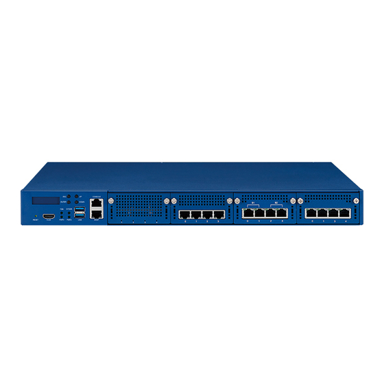
▪ 1 x RJ45 console port ▪ 1 x 550W CRPS (1+1) Redundant power supply ▪ 4 x LAN module slot (Gen Z) ▪ 2 x 2.5” SATA 3.0 SSD (optional) Copyright © 2025 NEXCOM International Co., Ltd. All Rights Reserved. NSA 5200 User Manual... -
Page 16: Hardware Specifications
LAN Slot 4 Connector Type Signal PCIe 5.0 x8 PCIe 5.0 x8 2 x PCIe 4.0 x4 2 x PCIe 3.0 x4 ▪ 3 x Swappable fan Copyright © 2025 NEXCOM International Co., Ltd. All Rights Reserved. NSA 5200 User Manual... - Page 17 Used to connect USB 3.0/2.0/1.1 devices. 9. LED Indicators Indicate the FAN, SYS, PWR1, and PWR2. 10. HDMI Port ® Used to connect to a display through an HDMI cable. ® Copyright © 2025 NEXCOM International Co., Ltd. All Rights Reserved. NSA 5200 User Manual...
-
Page 18: Rear Panel
Press to power on or off the system. 12. Swappable Smart Fans 13. AC Power Inlets Connect each AC cord to the dual redundant power inlets. Copyright © 2025 NEXCOM International Co., Ltd. All Rights Reserved. NSA 5200 User Manual... -
Page 19: Mechanical Dimensions
Chapter 1: Product Introduction Mechanical Dimensions 438.00 Copyright © 2025 NEXCOM International Co., Ltd. All Rights Reserved. NSA 5200 User Manual... -
Page 20: Chapter 2: Jumpers And Connectors
Static electricity can damage many of the electronic ▪ Use correct screws and do not over tighten screws. components. Humid environments tend to have less static electricity than Copyright © 2025 NEXCOM International Co., Ltd. All Rights Reserved. NSA 5200 User Manual... -
Page 21: Jumper Settings
(on) and open (off). Two-Pin Jumpers: Open (Left) and Short (Right) Three-Pin Jumpers: Pins 1 and 2 are Short Copyright © 2025 NEXCOM International Co., Ltd. All Rights Reserved. NSA 5200 User Manual... -
Page 22: Locations Of The Jumpers And Connectors
Chapter 2: Jumpers and Connectors Locations of the Jumpers and Connectors The following figure shows the mainboard used in the NSA 5200, and indicates the locations of the jumpers and connectors. For detailed pin FAN1 FAN2 FAN3 FAN4 settings and definitions of the jumpers and connectors marked in pink on the figure, please refer to this section. -
Page 23: Jumper
Connector location: JP2 Definition Definition 3.3V CMOS AT_ATX_SEL Default Setting Status 1-3 On Normal (default) 3-5 On Clear CMOS Default Setting Status 2-4 On ATX (default) 4-6 On Copyright © 2025 NEXCOM International Co., Ltd. All Rights Reserved. NSA 5200 User Manual... -
Page 24: Internal Connectors
Power Switch Connector location: BIOS_J1, BIOS_J2 Connector type: 1x2 2-Pin (2.0 mm header) Connector location: CN1 Definition Definition Definition 3.3V Power button 3.3V RST# MOSI MISO Copyright © 2025 NEXCOM International Co., Ltd. All Rights Reserved. NSA 5200 User Manual... -
Page 25: Ocp 4C+Genz Pcie Gen5 Slot 1 (From Cpu Peg)
SLOT1_PERST0_N OCP A11 OCP_B11 SLOT1_PERST1_N 3.3V AUX OCP A12 OCP_B12 SLOT1_PRSNTB2_N AUX_PWR_EN_MAIN OCP A13 OCP_B13 OCP A14 SLOT1_RTB_CLK_IN OCP_B14 SLOT1_RTB_CRSDV REFCLK1_SLOT1_DN REFCLK0_SLOT1_DN Continued on next page Copyright © 2025 NEXCOM International Co., Ltd. All Rights Reserved. NSA 5200 User Manual... - Page 26 PEG0_TXN2 PEG0_RXP2 PEG0_TXP2 PEG0_RXN3 PEG0_TXN3 PEG0_RXP3 PEG0_TXP3 PEG0_RXN4 PEG0_TXN4 PEG0_RXP4 PEG0_TXP4 PEG0_RXN5 PEG0_TXN5 PEG0_RXP5 PEG0_TXP5 PEG0_RXN6 PEG0_TXN6 PEG0_RXP6 PEG0_TXP6 PEG0_RXN7 PEG0_TXN7 PEG0_RXP7 PEG0_TXP7 SLOT1_PRSNTB1_N SLOT1_PRSNTB0_N SLOT1_PRSNTB3_N Copyright © 2025 NEXCOM International Co., Ltd. All Rights Reserved. NSA 5200 User Manual...
-
Page 27: Ocp 4C+Genz Pcie Gen5 Slot 2 (From Cpu Peg)
SLOT2_PERST0_N OCP A11 OCP_B11 SLOT2_PERST1_N 3.3V AUX OCP A12 OCP_B12 PEG0_SLOT2_PRSNTB2_N AUX_PWR_EN_MAIN OCP A13 OCP_B13 OCP A14 SLOT2_RTB_CLK_IN OCP_B14 SLOT2_RTB_CRSDV REFCLK1_SLOT2_DN REFCLK0_SLOT2_DN Continued on next page Copyright © 2025 NEXCOM International Co., Ltd. All Rights Reserved. NSA 5200 User Manual... - Page 28 PEG0_TXN10 PEG0_RXP10 PEG0_TXP10 PEG0_RXN11 PEG0_TXN11 PEG0_RXP11 PEG0_TXP11 PEG0_RXN12 PEG0_TXN12 PEG0_RXP12 PEG0_TXP12 PEG0_RXN13 PEG0_TXN13 PEG0_RXP13 PEG0_TXP13 PEG0_RXN14 PEG0_TXN14 PEG0_RXP14 PEG0_TXP14 PEG0_RXN15 PEG0_TXN15 PEG0_RXP15 PEG0_TXP15 SLOT2_PRSNTB1_N SLOT2_PRSNTB0_N SLOT2_PRSNTB3_N Copyright © 2025 NEXCOM International Co., Ltd. All Rights Reserved. NSA 5200 User Manual...
-
Page 29: Ocp 4C+Genz Pcie Gen4 Slot 3 (From Pch Hsio)
SLOT3_PERST0_N OCP A11 OCP_B11 SLOT3_PERST1_N 3.3V AUX OCP A12 OCP_B12 SLOT3_PRSNTB2_N AUX_PWR_EN_MAIN OCP A13 OCP_B13 OCP A14 SLOT3_RTB_CLK_IN OCP_B14 SLOT3_RTB_CRSDV REFCLK1_SLOT3_DN REFCLK0_SLOT3_DN Continued on next page Copyright © 2025 NEXCOM International Co., Ltd. All Rights Reserved. NSA 5200 User Manual... - Page 30 PCIE_SLOT3_TXN2 SLOT3_RXP2 PCIE_SLOT3_TXP2 SLOT3_RXN3 PCIE_SLOT3_TXN3 SLOT3_RXP3 PCIE_SLOT3_TXP3 SLOT3_RXN4 PCIE_SLOT3_TXN4 SLOT3_RXP4 PCIE_SLOT3_TXP4 SLOT3_RXN5 PCIE_SLOT3_TXN5 SLOT3_RXP5 PCIE_SLOT3_TXP5 SLOT3_RXN6 PCIE_SLOT3_TXN6 SLOT3_RXP6 PCIE_SLOT3_TXP6 SLOT3_RXN7 PCIE_SLOT3_TXN7 SLOT3_RXP7 PCIE_SLOT3_TXP7 SLOT3_PRSNTB1_N SLOT3_PRSNTB0_N SLOT3_PRSNTB3_N Copyright © 2025 NEXCOM International Co., Ltd. All Rights Reserved. NSA 5200 User Manual...
-
Page 31: Ocp 4C+Genz Pcie Gen3 Slot 4 (From Pch Hsio)
SLOT4_PERST0_N OCP A11 OCP_B11 SLOT4_PERST1_N 3.3V AUX OCP A12 OCP_B12 SLOT4_PRSNTB2_N AUX_PWR_EN_MAIN OCP A13 OCP_B13 OCP A14 SLOT4_RTB_CLK_IN OCP_B14 SLOT4_RTB_CRSDV REFCLK1_SLOT4_DN REFCLK0_SLOT4_DN Continued on next page Copyright © 2025 NEXCOM International Co., Ltd. All Rights Reserved. NSA 5200 User Manual... - Page 32 PCIE_SLOT4_TXN2 SLOT4_RXP2 PCIE_SLOT4_TXP2 SLOT4_RXN3 PCIE_SLOT4_TXN3 SLOT4_RXP3 PCIE_SLOT4_TXP3 SLOT4_RXN4 PCIE_SLOT4_TXN4 SLOT4_RXP4 PCIE_SLOT4_TXP4 SLOT4_RXN5 PCIE_SLOT4_TXN5 SLOT4_RXP5 PCIE_SLOT4_TXP5 SLOT4_RXN6 PCIE_SLOT4_TXN6 SLOT4_RXP6 PCIE_SLOT4_TXP6 SLOT4_RXN7 PCIE_SLOT4_TXN7 SLOT4_RXP7 PCIE_SLOT4_TXP7 SLOT4_PRSNTB1_N SLOT4_PRSNTB0_N SLOT4_PRSNTB3_N Copyright © 2025 NEXCOM International Co., Ltd. All Rights Reserved. NSA 5200 User Manual...
-
Page 33: Fan Slot
Connector type: PCIe x1 slot Connector location: FAN1, FAN2, FAN3 A1/B1 B18/B18 Definition Definition Definition Definition FAN present 3.3V 3.3V SMBCLK FAN PWM SMBDAT FAN TACH 3.3V 3.3V Copyright © 2025 NEXCOM International Co., Ltd. All Rights Reserved. NSA 5200 User Manual... -
Page 34: Fan Slot
Chapter 2: Jumpers and Connectors FAN Slot Connector type: 1x4 4-Pin (2.54mm wafer) Connector location: FAN4 Definition Definition FAN4_TACH FAN4_PWM Copyright © 2025 NEXCOM International Co., Ltd. All Rights Reserved. NSA 5200 User Manual... -
Page 35: Pcie Slot (For I/O Board)
USB OC I210 PCIE RXN0 USB3.2 Gen1 TXP1 I210 PCIE RXP0 USB3.2 Gen1 TXN1 I210 PCIE TXN0 USB3.2 Gen1 RXP1 I210 PCIE TXP0 Continued on next page Copyright © 2025 NEXCOM International Co., Ltd. All Rights Reserved. NSA 5200 User Manual... - Page 36 3.3V AUX HDMI TX2 DP 3.3V AUX 3.3V AUX LCM Uart TX LCM Uart RX 3.3V (EC) 3.3V (EC) HDMI TX3 DN 3.3V (EC) 3.3V (EC) Copyright © 2025 NEXCOM International Co., Ltd. All Rights Reserved. NSA 5200 User Manual...
-
Page 37: Crps Power Golden Finger
PSU2 Alert PMBUS SCL PSU power on PSU1 Alert Standby 12V PSU1/PSU2 Alert SENSE PSU1 power OK PSU present1 PSU2 power OK SENSE 3.3V PSU present2 Copyright © 2025 NEXCOM International Co., Ltd. All Rights Reserved. NSA 5200 User Manual... -
Page 38: Sata Power Connector
Chapter 2: Jumpers and Connectors SATA Power Connector Connector type: 1x4 4-Pin Connector location: J3 Definition Copyright © 2025 NEXCOM International Co., Ltd. All Rights Reserved. NSA 5200 User Manual... -
Page 39: M.2 Key M Connector
Definition Definition Definition PCIE_NVME_TXN3 PCIE_NVME_RXP1 3.3V 3.3V PCIE_NVME_TXN2 PCIE_NVME_TXP3 3.3V 3.3V PCIE_NVME_TXP2 PCIE_NVME_TXN1 PCIE_NVME_RXN3 3.3V PCIE_NVME_TXP1 PCIE_NVME_RXP3 PCIE_NVME_RXN2 3.3V PCIE_NVME_RXN1 PCIE_NVME_RXP2 M.2_LED_N Continued on next page Copyright © 2025 NEXCOM International Co., Ltd. All Rights Reserved. NSA 5200 User Manual... - Page 40 Chapter 2: Jumpers and Connectors Definition Definition Definition Definition PCIE_NVME_RXN0 RST_M.2_N PCIE_NVME_RXP0 PCIe CLKREQ# PCIe REFCLKn 3.3V PCIe Wake (NC) PCIe REFCLKp 3.3V PCIE_NVME_TXN0 3.3V PCIE_NVME_TXP0 Copyright © 2025 NEXCOM International Co., Ltd. All Rights Reserved. NSA 5200 User Manual...
-
Page 41: Sata Gen3 Connector
Chapter 2: Jumpers and Connectors SATA Gen3 Connector Connector location: SATA1, SATA2 Definition Copyright © 2025 NEXCOM International Co., Ltd. All Rights Reserved. NSA 5200 User Manual... -
Page 42: Locations Of The Front Panel Board Connectors
Locations of the Front Panel Board Connectors The following figure shows the front panel board used in the NSA 5200, and indicates the locations of the connectors. Refer to this section for detailed pin settings and definitions of the connectors marked in pink on the figure below. -
Page 43: Golden Finger
Definition Definition Definition USB32_GEN11_RXN1 USB32_GEN11_TXP0 USB32_GEN11_TXN0 USB32_GEN11_RXP0 USB32_GEN11_RXN0 USB2_DP2 USB2_DN2 EC_UART1_DTR# EC_UART1_CTS# USB2_DP1 USB2_DN1 USB_OC0_N PCIE_I210_RXN0 PCIE_I210_RXP0 USB32_GEN11_TXP1 USB32_GEN11_TXN1 PCIE_I210_TXN0 PCIE_I210_TXP0 USB32_GEN11_RXP1 Continued on next page Copyright © 2025 NEXCOM International Co., Ltd. All Rights Reserved. NSA 5200 User Manual... - Page 44 +P5V +P5V EC_UART1_RTS# +P5V +P5V DDI1_TX1_DN DDI1_TX1_DP +P3V3 +P3V3 SYS_UART1_TXD +P3V3 +P3V3 SYS_UART1_RXD DDI1_TX2_DN +P3V3_AUX +P3V3_AUX DDI1_TX2_DP +P3V3_AUX +P3V3_AUX LCM_UART2_TXD LCM_UART2_RXD +P3V3_EC +P3V3_EC DDI1_TX3_DN +P3V3_EC +P3V3_EC Copyright © 2025 NEXCOM International Co., Ltd. All Rights Reserved. NSA 5200 User Manual...
-
Page 45: Hdmi ® Connector
Connector ® Connector number: HDMI1 Connector number: J1 Definition Definition Definition HDMI_DATA2_P_C HDMI_CLK_N_C SP_LCM_RXD HDMI_DATA2_N_C SP_LCM_TXD HDMI_DATA1_P_C +P5V HDMI_CLK HDMI_DATA1_N_C HDMI_DAT HDMI_DATA0_P_C HDMI_PWR_C HDMI_DATA0_N_C HDMI_HPD_C HDMI_CLK_P_C Copyright © 2025 NEXCOM International Co., Ltd. All Rights Reserved. NSA 5200 User Manual... -
Page 46: Console Ports
Definition LANA_LED_LINK1G#_R CGND MDI_0_P_A_R LANA_LED_LINK100#_R COM1_RTS_N CGND MDI_0_N_A_R P3V3_LANA_R COM1_DTR_N CGND MDI_1_P_A_R LANA_LED_ACT#_R COM1_TXD MDI_1_N_A_R MDI_2_P_A_R COM1_DCD_N MDI_2_N_A_R CGND COM1_RXD MDI_3_P_A_R CGND COM1_DSR_N MDI_3_N_A_R CGND COM1_CTS_N Copyright © 2025 NEXCOM International Co., Ltd. All Rights Reserved. NSA 5200 User Manual... -
Page 47: Led Indicators
Chapter 2: Jumpers and Connectors LED Indicators Connector number: LED2 Connector number: LED1 Definition Definition FP_POWER_LED_R EC_SATA_LED_R_N FP_SYSTEM_LED_R EC_GPIO_LED_R Copyright © 2025 NEXCOM International Co., Ltd. All Rights Reserved. NSA 5200 User Manual... -
Page 48: Reset Button
Connector number: SW1 Connector number: USB2 Definition Definition Definition +P5V_USB_OCP +P5V_USB_OCP FP_RST_BTN_R_N USB2N1_C USB2N2_C CGND USB2P1_C USB2P2_C CGND USB3RN0_C USB3RN1_C USB3RP0_C USB3RP1_C USB3TN0_C USB3TN1_C USB3TP0_C USB3TP1_C Copyright © 2025 NEXCOM International Co., Ltd. All Rights Reserved. NSA 5200 User Manual... -
Page 49: Block Diagram
4P FAN Wafer Run BMC VGA(Rear) Socket NPCE68AL CONN Status CONN Indicator (For AST2600) UART RESET PWRBTN Front I/O Board STD PCIe Slot Level Shift RJ45 Console Copyright © 2025 NEXCOM International Co., Ltd. All Rights Reserved. NSA 5200 User Manual... -
Page 50: Chapter 3: Bios Setup
This chapter describes how to use the BIOS setup program for NSA 5200. The The settings made in the setup program affect how the computer performs. BIOS screens provided in this chapter are for reference only and may change if It is important, therefore, first to try to understand all the setup options, and the BIOS is updated in the future. -
Page 51: Default Configuration
Powering on the computer and immediately pressing allows you to enter Setup. Load optimized default values. Saves and exits the Setup program. Press <Enter> to enter the highlighted sub-menu Copyright © 2025 NEXCOM International Co., Ltd. All Rights Reserved. NSA 5200 User Manual... - Page 52 When “” appears on the left of a particular field, it indicates that a submenu which contains additional options are available for that field. To display the submenu, move the highlight to that field and press Copyright © 2025 NEXCOM International Co., Ltd. All Rights Reserved. NSA 5200 User Manual...
-
Page 53: Bios Setup Utility
24-hour military-time clock. For example, 1 p.m. is 13:00:00. Hour displays hours from 00 to 23. Minute displays minutes from 00 to 59. Second displays seconds from 00 to 59. Copyright © 2025 NEXCOM International Co., Ltd. All Rights Reserved. NSA 5200 User Manual... -
Page 54: Advanced
Setting incorrect field values may cause the system to malfunction. Copyright © 2025 NEXCOM International Co., Ltd. All Rights Reserved. NSA 5200 User Manual... -
Page 55: Cpu Configuration
Enable increase maximum CPU frequency to maximum Turbo ration. Must be enabled to allow overclocking functionality. The default setting is Enabled. CPU C states Enable or disable CPU C states. Copyright © 2025 NEXCOM International Co., Ltd. All Rights Reserved. NSA 5200 User Manual... - Page 56 Chapter 3: BIOS Setup CPU Information This sub-menu displays the CPU information of your system. Copyright © 2025 NEXCOM International Co., Ltd. All Rights Reserved. NSA 5200 User Manual...
-
Page 57: Memory Information
This section is used to configure the PCIe setting. SR-IOV Support If system has SR-IOV capable PCIe devices, this option enables or disables single root IO Virtualization support. Copyright © 2025 NEXCOM International Co., Ltd. All Rights Reserved. NSA 5200 User Manual... -
Page 58: Pch Configuration
When this is disabled, ME will be put into temporarily disabled mode. Legacy support allows non-EFI devices to function. By default, this is enabled, as disabling this option will greatly limit devices the USB controllers can use. Copyright © 2025 NEXCOM International Co., Ltd. All Rights Reserved. NSA 5200 User Manual... -
Page 59: Power Management
Specify what state to go to when power is re-applied after a power failure (G3 state). Fan1 ~ Fan4 Out PWM The valid range is 0 to 100. It is 50 by default for Fan1, Fan2, Fan3, and Fan4. Copyright © 2025 NEXCOM International Co., Ltd. All Rights Reserved. NSA 5200 User Manual... - Page 60 Four levels of temperature are configurable for fans among 0 to 100°C. Speed Levels (PWM1/2/3 & Critical PWM) for Smart Fans Four levels of temperature are configurable for fans among 0 to 100%. Copyright © 2025 NEXCOM International Co., Ltd. All Rights Reserved. NSA 5200 User Manual...
-
Page 61: Serial Port Console Redirection
Enter the legacy console redirection settings. 9600, 19200, 38400, 57600, and 115200. Console Redirection EMS Data Bits Enable or disable consle redirection EMS. The options are 7 and 8. Copyright © 2025 NEXCOM International Co., Ltd. All Rights Reserved. NSA 5200 User Manual... - Page 62 Recorder Mode With this mode enabled, only text will be sent. This is to capture the terminal data. Resolution 100x31 Enable or disable extended terminal resolution. Copyright © 2025 NEXCOM International Co., Ltd. All Rights Reserved. NSA 5200 User Manual...
- Page 63 When Bootloader is selected, legacy console redirection is disabled before booting to legacy OS. When Always Enable (default) is selected, legacy console redirection is enabled for legacy OS. Copyright © 2025 NEXCOM International Co., Ltd. All Rights Reserved. NSA 5200 User Manual...
-
Page 64: Trusted Computing
Device. TCG EFI protocol and INT1A interface will not be available. SHA256 PCR Bank Enable or disable SHA256 PCR Bank. SHA384 PCR Bank Enable or disable SHA384 PCR Bank. Copyright © 2025 NEXCOM International Co., Ltd. All Rights Reserved. NSA 5200 User Manual... -
Page 65: Nvme Configuration
Chapter 3: BIOS Setup NVMe Configuration This section is used to configure the NVMe devices installed. The options will become available upon installation of the NVMe device. Copyright © 2025 NEXCOM International Co., Ltd. All Rights Reserved. NSA 5200 User Manual... -
Page 66: Security
Standard Fixed secure boot policy. Press to enter Secure Boot submenu. Custom Secure boot policy variables can be configured by a physically present user without full authentication. Copyright © 2025 NEXCOM International Co., Ltd. All Rights Reserved. NSA 5200 User Manual... - Page 67 Select Yes or No to restore the factory defaults. Enroll Efi Image Allow Efi image to run in Secure Boot mode. Enroll SHA256 Hash certificate of a PE image into Authorized Signature Database (db). Copyright © 2025 NEXCOM International Co., Ltd. All Rights Reserved. NSA 5200 User Manual...
- Page 68 1. Public Key Certificate: a) EFI_SIGNATURE_LIST b) EFI_CERT_X509 (DER) c) EFI_CERT_RSA2048 (bin) d) EFI_CERT_SHAXXX 2. Authenticated UEFI Variable 3. EFI PE/COFF Image (SHA256) Key Source: Factory, Modified, Mixed Copyright © 2025 NEXCOM International Co., Ltd. All Rights Reserved. NSA 5200 User Manual...
-
Page 69: Boot
NumLock on wherein the function of the numeric keypad is the number keys. When set to Off, the function of the numeric keypad is the arrow keys. Copyright © 2025 NEXCOM International Co., Ltd. All Rights Reserved. NSA 5200 User Manual... -
Page 70: Save & Exit
<Enter>. You may be prompted to confirm again before exiting. Restore Defaults To restore the BIOS to default settings, select this field then press <Enter>. A dialog box will appear. Confirm by selecting Yes. Copyright © 2025 NEXCOM International Co., Ltd. All Rights Reserved. NSA 5200 User Manual...
Need help?
Do you have a question about the NSA 5200 and is the answer not in the manual?
Questions and answers