
Related Manuals for Nexcom NISE 3520 Series


Summary of Contents for Nexcom NISE 3520 Series
- Page 1 NEXCOM International Co., Ltd. Industrial Computing Solutions Fan-less Computer NISE 3520 Series User Manual NEXCOM International Co., Ltd. www.nexcom.com Published January 2013...
-
Page 2: Table Of Contents
9V-30V DC Input .................19 Front Panel ..................4 GPIO Connector ................19 Rear Panel ..................5 Serial Interface (COM 1 - COM 4) ..........20 Mechanical Dimensions ................6 LAN1 Port ..................22 Copyright © 2013 NEXCOM International Co., Ltd. All Rights Reserved. NISE 3520 Series User Manual... - Page 3 Express KVM........Mini-PCIe Slot ................39 Smart Fan1 Connector ..............40 Appendix E: Intel Manageability Command Tool - Smart Fan2 Connector ..............40 KVM............ External LED Connector ...............41 Copyright © 2013 NEXCOM International Co., Ltd. All Rights Reserved. NISE 3520 Series User Manual...
-
Page 4: Preface
Acknowledgements The product(s) described in this manual complies with all applicable Euro- NISE 3520 Series is a trademark of NEXCOM International Co., Ltd. All pean Union (CE) directives if it has a CE marking. For computer systems to other product names mentioned herein are registered trademarks of their remain CE compliant, only CE-compliant parts may be used. -
Page 5: Rohs Compliance
0.1% or 1,000ppm, and Polybrominated diphenyl Ethers (PBDE) < 0.1% or 1,000ppm. In order to meet the RoHS compliant directives, NEXCOM has established an engineering and manufacturing task force in to implement the introduction of green products. The task force will ensure that we follow the standard... -
Page 6: Warranty And Rma
? Replace with 3rd party products if needed. the RMA number apply process. ? If RMA goods can not be repaired, NEXCOM will return it to the cus- tomer without any charge. ? Customers can send back the faulty products with or without acces- sories (manuals, cable, etc.) and any components from the card, such as... -
Page 7: Safety Information
There is a danger of explosion if battery is incorrectly replaced. Replace only with the same or equivalent type recommended by the manufactur- er. Discard used batteries according to the manufacturer’s instructions. Copyright © 2013 NEXCOM International Co., Ltd. All Rights Reserved. NISE 3520 Series User Manual... -
Page 8: Safety Precautions
11. All cautions and warnings on the equipment should be noted. 19. The computer is provided with CD drives that comply with the ap- propriate safety standards including IEC 60825. viii Copyright © 2013 NEXCOM International Co., Ltd. All Rights Reserved. NISE 3520 Series User Manual... -
Page 9: Technical Support And Assistance
Technical Support and Assistance Conventions Used in this Manual Warning: Information about certain situations, which if not 1. For the most updated information of NEXCOM products, visit NEX- observed, can cause personal injury. This will prevent injury to COM’s website at www.nexcom.com. -
Page 10: Global Service Contact Information
Chongde Rd., Beitun Dist., Shanghai, 200062, China Fax: +86-27-8722-7400 Taichung City 406, R.O.C. Tel: +86-21-6150-8008 Email: sales@nexcom.cn Tel: +886-4-2249-1179 Fax: +86-21-3251-6358 www.nexcom.cn Fax: +886-4-2249-1172 Email: sales@nexcom.cn www.nexcom.com.tw www.nexcom.cn Copyright © 2013 NEXCOM International Co., Ltd. All Rights Reserved. NISE 3520 Series User Manual... - Page 11 Fax: +33 (0) 1 40 90 31 01 Email: sales.uk@nexcom.eu Email: sales.fr@nexcom.eu www.nexcom.eu www.nexcom.eu Germany NEXCOM GmbH Leopoldstraße Business Centre, Leopoldstraße 244, 80807 Munich, Germany Tel: +49-89-208039-278 Fax: +49-89-208039-279 Email: sales.de@nexcom.eu www.nexcom.eu Copyright © 2013 NEXCOM International Co., Ltd. All Rights Reserved. NISE 3520 Series User Manual...
-
Page 12: Package Contents
Preface Package Contents Before continuing, verify that the NISE 3520 Series package that you received is complete. Your package should have all the items listed in the following table. Item Name 60233POW33X00 DC Power Cord 6012200053X00 PE ZIPPER BAG #3, 100x70mm... -
Page 13: Ordering Information
Preface Ordering Information The following provides ordering information for NISE 3520 Series. • Barebone NISE 3520 (P/N: 10J00352000X0) RoHS Compliant - Intel ® Core™ i7/i5 fanless system - 1 x PCI expansion slot NISE 3520P2 (P/N: 10J00352002X0) RoHS Compliant - Intel... -
Page 14: Chapter 1: Product Introduction
• 3x RS232 and 1x RS232/422/485 with Auto Flow Control • Supports ATX power mode and PXE/WOL • 1x PCI (NISE 3520) 2x PCI (NISE 3520P2) 1x PCI, 1x PCIe x1 (NISE 3520P2E) Copyright © 2013 NEXCOM International Co., Ltd. All Rights Reserved. NISE 3520 Series User Manual... -
Page 15: Hardware Specifications
- 1x PCI expansion: Add-on card length: 169mm max - 1 PCIe x1 expansion: Add-on card length: 169mm max - 1x Mini PCIe socket with GSM Audio Copyright © 2013 NEXCOM International Co., Ltd. All Rights Reserved. NISE 3520 Series User Manual... - Page 16 (According to IEC60068-2-1, IEC60068-2-2, IEC60068-2-14) • Storage temperature: -20°C to 80°C • Relative humidity: 10% to 93% (Non-Condensing) Certifications • CE approval • FCC Class A Copyright © 2013 NEXCOM International Co., Ltd. All Rights Reserved. NISE 3520 Series User Manual...
-
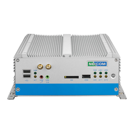
Page 17: Getting To Know Nise 3520 Series
Indicates the GSM’s RF On status. Power On/Off Switch Press to power-on or power-off the system. Indicates the GSM’s RF Active status. GSM Mic-in Used to connect an external microphone. Copyright © 2013 NEXCOM International Co., Ltd. All Rights Reserved. NISE 3520 Series User Manual... -
Page 18: Rear Panel
The GPIO connector supports 4 digital input and 4 digital output. COM1 to COM4 The DB44 port supports 3 RS232 and 1 RS232/422/485 compatible serial devices. Copyright © 2013 NEXCOM International Co., Ltd. All Rights Reserved. NISE 3520 Series User Manual... -
Page 19: Mechanical Dimensions
Chapter 1: Product Introduction Mechanical Dimensions NISE 3520 195.00 207.00 219.00 Copyright © 2013 NEXCOM International Co., Ltd. All Rights Reserved. NISE 3520 Series User Manual... - Page 20 Chapter 1: Product Introduction NISE 3520P2/3520P2E 195.00 207.00 219.00 Copyright © 2013 NEXCOM International Co., Ltd. All Rights Reserved. NISE 3520 Series User Manual...
-
Page 21: Chapter 2: Jumpers And Connectors
This chapter describes how to set the jumpers on the motherboard. Note tronic components. Humid environment tend to have less static electric- that the following procedures are generic for all NISE 3520 series. ity than dry environments. A grounding strap is warranted whenever danger of static electricity exists. -
Page 22: Jumper Settings
(on) and open (off). Two-Pin Jumpers: Open (Left) and Short (Right) Three-Pin Jumpers: Pins 1 and 2 Are Short Copyright © 2013 NEXCOM International Co., Ltd. All Rights Reserved. NISE 3520 Series User Manual... -
Page 23: Locations Of The Jumpers And Connectors
Locations of the Jumpers and Connectors NISB 3520 The figure below is the top view of the NISB 3520 main board which is the main board used in the NISE 3520 Series system. It shows the locations of the jumpers and connectors. - Page 24 Chapter 2: Jumpers and Connectors The figure below is the bottom view of the NISB 3520 main board. CN16 CN17 CN12 CN13 CN15 CN14 Copyright © 2013 NEXCOM International Co., Ltd. All Rights Reserved. NISE 3520 Series User Manual...
-
Page 25: Jumpers
Connector type: 1x3 3-pin header, 2.54 mm pitch Connector location: JP4 Settings 1-2 On *Normal 2-3 On CMOS Clear 1-2 On: default Definition RTCRST#_PU RTCRST# CLR_CMOS Copyright © 2013 NEXCOM International Co., Ltd. All Rights Reserved. NISE 3520 Series User Manual... -
Page 26: Connectors Pin Definitions
Connector type: Dual USB port Connector location: CN10 Status LED Color Green Definition Definition Yellow P5V_USB_P89 USB9+ USB8- USB1_GND USB8+ USB1_GND USB1_GND USB1_GND P5V_USB_P89 USB1_GND USB9- USB1_GND Copyright © 2013 NEXCOM International Co., Ltd. All Rights Reserved. NISE 3520 Series User Manual... -
Page 27: Mic-In Jack
Mic-in Jack Line-out Jack Connector type: 5-pin jack, 25.9x12.6x17.0mm Connector type: 5-pin jack, 25.9x12.6x17.0mm Connector location: CN20 Connector location: CN19 Definition Definition MIC_L LOUT_R MIC_R LOUT_L Copyright © 2013 NEXCOM International Co., Ltd. All Rights Reserved. NISE 3520 Series User Manual... -
Page 28: Sim Card Connector
Definition HDMID_D2P HDMID_GND HDMID_D2N HDMID_D1P Definition Definition HDMID_GND HDMID_D1N 3VSB RESET HDMID_D0P HDMID_GND HDMID_D0N HDMID_LKP VCCP DATA HDMID_GND HDMID_LKN HDMID_CTL_CLK HDMID_CTL_SDA HDMID_GND VCC5 HDMID_GND HDMID_GND Copyright © 2013 NEXCOM International Co., Ltd. All Rights Reserved. NISE 3520 Series User Manual... -
Page 29: Status Indicators
LAN1/LAN2 Link/Active LEDs Connector location: LED3 Connector location: LED1 and LED2 LINK1 LINK2 ACT1 ACT2 Status LED Color Definition Green LAN2_LINK_N Yellow LAN2_ACT_N LAN2_LINK_P LAN2_ACT_P Copyright © 2013 NEXCOM International Co., Ltd. All Rights Reserved. NISE 3520 Series User Manual... -
Page 30: Atx Power On/Off Switch
Chapter 2: Jumpers and Connectors ATX Power On/Off Switch Connector location: SW1 Definition Blue light Red light Definition Definition PBT_PU PBT_PU PWRLED_N PWRLED_P Copyright © 2013 NEXCOM International Co., Ltd. All Rights Reserved. NISE 3520 Series User Manual... -
Page 31: External I/O Interface - Rear Panel
Connector type: 2-pin switch Connector type: PS/2, Mini-DIN-6; JST-2.0mm-M-180 Connector location: J3 Connector location: J5 Definition Definition Definition PBT_PU 5VSB_KB KDAT KCLK MDAT MCLK KBMS_GND Copyright © 2013 NEXCOM International Co., Ltd. All Rights Reserved. NISE 3520 Series User Manual... -
Page 32: 30V Dc Input
Connector type: DB-15 port; 2x5 10-pin header, 2.0 mm-M-180 Connector location: JP2 Definition Definition Definition Definition VCC5 SIO_GPO24 SIO_GPI20 SIO_GPO25 SIO_GPI21 SIO_GPO26 SIO_GPI22 SIO_GPO27 SIO_GPI23 Copyright © 2013 NEXCOM International Co., Ltd. All Rights Reserved. NISE 3520 Series User Manual... -
Page 33: Serial Interface (Com 1 - Com 4)
GND_COM CN10_21 CN10_22 CN10_23 CN10_24 COM port GND_COM CN10_26 CN10_27 CN10_28 CN10_29 GND_COM CN10_31 CN10_32 CN10_33 CN10_34 GND_COM CN10_36 CN10_37 CN10_38 SP4_RI_TI GND_COM GND_COM GND_COM Copyright © 2013 NEXCOM International Co., Ltd. All Rights Reserved. NISE 3520 Series User Manual... - Page 34 COM3 (RS232) labelled “C“ on DB9 Cable Connector DB44 Pin # DB9 Pin # Def. DB44 Pin # DB9 Pin # Def. DCD3 RXD3 TXD3 DTR3 DSR3 RTS3 CTS3 Copyright © 2013 NEXCOM International Co., Ltd. All Rights Reserved. NISE 3520 Series User Manual...
-
Page 35: Lan1 Port
Blinking Always Lighted No Acitivity No Link Definition Definition LAN1_M0P LAN1_M0N LAN1_M1P LAN1_M2P LAN1_M2N LAN1_M1N LAN1_M3P LAN1_M3N LAN1_LED1P LAN1_LED_ACT# LAN1_LED2P LAN1_LINK# UL_GND UL_GND UL_GND UL_GND Copyright © 2013 NEXCOM International Co., Ltd. All Rights Reserved. NISE 3520 Series User Manual... -
Page 36: Lan2 Port
UL_GND UL_GND UL_GND Definition Definition P5V_USB_P01 UL_GND LAN2_M0P LAN2_M0N USB1- UL_GND LAN2_M1P LAN2_M2P LAN2_M2N LAN2_M1N LAN2_M3P LAN2_M3N LAN2_LED1P LAN2_LED_ACT# LAN2_LED2P LAN2_LINK# UL_GND UL_GND UL_GND UL_GND Copyright © 2013 NEXCOM International Co., Ltd. All Rights Reserved. NISE 3520 Series User Manual... -
Page 37: Usb2 Ports
GREEN_VGA DVI_GND USB2- UL_GND BLUE_VGA DATA_V USB2+ UL_GND DVI_GND HS_VGA UL_GND UL_GND DVI_GND VS_VGA P5V_USB_P23 UL_GND DVI_GND CLK_V USB3- UL_GND DVI_GND DVI_GND DVI_GND DVI_GND VGA_+5V Copyright © 2013 NEXCOM International Co., Ltd. All Rights Reserved. NISE 3520 Series User Manual... -
Page 38: Dvi-I Port
FRONT-JD DVI_GND FRONT_RCI HDMI_CTL_CLK HDMI_CTL_SDA DC_VSYNC_VGA HDMI_DATA1_N HDMI_DATA1_P DVI_GND HDMIC_PWR_S DVI_GND HDMIC_HPDET HDMI_DATA0_N HDMI_DATA0_P DVI_GND DC_DATA_VGA DC_CLK_VGA HDMI_LKP HDMI_LKN DC_RED_VGA DC_GREEN_VGA DC_BLUE_VGA DC_HSYNC_VGA DVI_GND DVI_GND Copyright © 2013 NEXCOM International Co., Ltd. All Rights Reserved. NISE 3520 Series User Manual... -
Page 39: Mic-In Jack
Chapter 2: Jumpers and Connectors Mic-in Jack Connector type: 5-pin jack, 25.9x12.6x17.0mm Connector location: CN11A Definition AU_GND MIC_OUT-L AU_GND MIC_JD1 MIC_OUT-R AU_GND AU_GND AU_GND AU_GND Copyright © 2013 NEXCOM International Co., Ltd. All Rights Reserved. NISE 3520 Series User Manual... -
Page 40: Internal Connectors
DC Power Output Connector Reset Connector Connector type: 2x2 AUX Power Connector type: 1x2 2-pin header, JST 2.5mm-M-90 Connector location: CON1 Connector location: J2 Definition PM_RESET#_JP Definition Copyright © 2013 NEXCOM International Co., Ltd. All Rights Reserved. NISE 3520 Series User Manual... -
Page 41: Smbus Data/Clk Connector
Connector type: 1x3 3-pin header 2.54mm-M-180 Connector type: 1x3 3-pin header 2.54mm-M-180 Connector location: J8 Connector location: JP3 Definition Definition SMB_CLK VCC5 SMB_DATA PANEL1_VDD VCC3 2-3 On: default Copyright © 2013 NEXCOM International Co., Ltd. All Rights Reserved. NISE 3520 Series User Manual... -
Page 42: Lvds Connectors
Definition Definition VCC5 L_DDC_CLK L_DDC_DATA PANEL1_BACKLIGHT LA_DATAP0 PANEL1_BACKLIGHT LA_DATAP3 LA_DATAN0 L_BKLTCTL_R LA_DATAN3 GND_LVDS LA_DATAP1 LA_CLKP LA_DATAN1 L_BKLTEN LA_CLKN GND_LVDS GND_LVDS PANEL1_BACKLIGHT LA_DATAP2 PANEL1_BACKLIGHT LA_DATAN2 GND_LVDS Copyright © 2013 NEXCOM International Co., Ltd. All Rights Reserved. NISE 3520 Series User Manual... -
Page 43: Line-In Connector
Connector type: 1x4 4-pin header 2.5mm-M-180 Connector type: Standard Serial ATAII 7P (1.27mm, SATA-M-180) Connector location: J15 Connector location: CN12 Definition Definition LINE1-LP SATA_TXP0 LINE1-JD SATA_TXN0 LINE1-RP SATA_RXN0 SATA_RXP0 Copyright © 2013 NEXCOM International Co., Ltd. All Rights Reserved. NISE 3520 Series User Manual... -
Page 44: Sata2 Port
Connector type: Standard Serial ATAII 7P (1.27mm, SATA-M-180) Connector type: 1x4 4-pin Wafer, 2.54mm-M-180 Connector location: CN13 Connector location: CN15 Definition Definition SATA_TXP1 +12V SATA_TXN1 SATA_RXN1 VCC5 SATA_RXP1 Copyright © 2013 NEXCOM International Co., Ltd. All Rights Reserved. NISE 3520 Series User Manual... -
Page 45: Sata2 Power Connector
Connector type: 1x4 4-pin Wafer, 2.54mm-M-180 Connector type: 1x2 2-pin JST wafer, 2.54mm pitch Connector location: CN14 Connector location: J16, J17 Definition Definition +12V +12V VCC5 Copyright © 2013 NEXCOM International Co., Ltd. All Rights Reserved. NISE 3520 Series User Manual... -
Page 46: Gps Connector
Connector type: 1x6 6-pin JST, 2.54 mm pitch Connector type: 1x3 3-pin JST wafer, 2.54mm pitch Connector location: J19 Connector location: J20 Definition Definition 3VSB V_IN LED_PWRN COM6_TXD COM6_RXD VCC3 Copyright © 2013 NEXCOM International Co., Ltd. All Rights Reserved. NISE 3520 Series User Manual... -
Page 47: Usb4 Connector
Connector type: 1x5 5-pin header 2.0mm -M-180 Connector location: J12 Connector location: J9 Definition Definition VCC5 P5V_USB_P1011 SP4_RI_T USB10- +12V USB10+ SP4_RI_T SP4_RI 4-5 On: default USB2_GND Copyright © 2013 NEXCOM International Co., Ltd. All Rights Reserved. NISE 3520 Series User Manual... -
Page 48: Com5 Connector
Connector type: 2x2 4-pin 2.0mm -M-180 Connector location: CN5 Connector location: JP1 Definition Definition Definition GPO_LED0 SP5_DCD SP5_RXD SP5_TXD SP5_DTR GPO_LED1 GND_COM5 SP5_DSR SP5_RTS SP5_CTS SP5_RI GND_COM5 Copyright © 2013 NEXCOM International Co., Ltd. All Rights Reserved. NISE 3520 Series User Manual... -
Page 49: Pci Slot
PCI_SLOT_PRSNT2# PCI_TRDY# VCC3 PCI_DEVSEL# PCI_STOP# 3VSB PCI_CLK1 VCC3 PCI_LOCK# PCI_SLOT_RST# SMBCLK_PCI PCI_PERR# VCC5 PCI_CLK0 SMBDATA_PCI VCC3 PCI_GNT#0 PCI_SERR# PCI_SLOT_REQ#0 PCI_PAR VCC3 PCI_SLOT_PME# VCC5 PCI_AD15 PCI_CBE#1 Copyright © 2013 NEXCOM International Co., Ltd. All Rights Reserved. NISE 3520 Series User Manual... - Page 50 PCI_AD13 PCI_AD11 PCI_AD12 PCI_AD10 PCI_AD9 PCI_CBE#0 PCI_AD8 VCC3 PCI_AD7 PCI_AD6 VCC3 PCI_AD4 PCI_AD5 PCI_AD3 PCI_AD2 PCI_AD0 PCI_AD1 VCC5 VCC5 PU1_REQ64# PU1_ACK64# VCC5 VCC5 VCC5 VCC5 Copyright © 2013 NEXCOM International Co., Ltd. All Rights Reserved. NISE 3520 Series User Manual...
-
Page 51: Pcie X4 Slot
+12V PCIE_RXP8_PCIE4 PCIE_RXN8_PCIE4 CL_CLK SMB_CLK PCIE_PRSNT2 CL_RST# SMB_DATA USB5+ CL_DATA VCC3 VCC3 USB5- VCC3 3VSB PLT_RST_DVO_PCIE# PCIE_WAKE# CLK_PCIE_PCIE4_P CLK_PCIE_PCIE4_N PCIE_TXP5_PCIE4 PCIE_TXN5_PCIE4 PCIE_RXP5_PCIE4 PCIE_RXN5_PCIE4 CLK_REQ#PCIE4 PCIE_TXP6_PCIE4 Copyright © 2013 NEXCOM International Co., Ltd. All Rights Reserved. NISE 3520 Series User Manual... -
Page 52: Mini-Pcie Slot
WLAN_ACT V1_5 Definition Definition 3VSB MIC_R 3VSB MIC_L LOUT_R V1_5 LOUT_L 3VSB UIM_DATA PCIE_MINI_CLK_N UIM_CLK PCIE_MINI_CLK_P UIM_RESET UIM_VCCP 3VSB PLT_RST PCIE_MINI_RXN 3VSB PCIE_MINI_RXP V1_5 SMB_CLK Copyright © 2013 NEXCOM International Co., Ltd. All Rights Reserved. NISE 3520 Series User Manual... -
Page 53: Smart Fan1 Connector
Connector type: 1x4 4-pin Wafer, 2.54mm-M-180 Connector type: 1x4 4-pin Wafer, 2.54mm-M-180 Connector location: J1 Connector location: J14 Definition Definition +12V +12V CPUFANIN_P SYSFANIN_P CPUFANOUT_R SYSFANOUT_R Copyright © 2013 NEXCOM International Co., Ltd. All Rights Reserved. NISE 3520 Series User Manual... -
Page 54: External Led Connector
External LED Connector Connector type: 2x7 14-pin header 2.54mm-M-180 Connector location: J4 Description Description LED_PWRN LED_PWRP HD_LEDN LED_HDDP LAN1_LINK# LAN1_LINKP LAN1_LED_ACT# LAN1_ACTP LAN2_LINK# LAN2_LINKP LAN2_LED_ACT# LAN2_ACTP Copyright © 2013 NEXCOM International Co., Ltd. All Rights Reserved. NISE 3520 Series User Manual... -
Page 55: Chapter 3: System Setup
1. The screws on the cover are used to secure the cover to the chassis. 2. Remove these screws and then put them in a safe place for later use. The dots denote the locations of the screws. Copyright © 2013 NEXCOM International Co., Ltd. All Rights Reserved. NISE 3520 Series User Manual... -
Page 56: Installing A Dimm
“key” on the socket. The key ensures the module can be plugged into the socket in only one direction. Ejector DIMM sockets Notch on the module Key on the socket Copyright © 2013 NEXCOM International Co., Ltd. All Rights Reserved. NISE 3520 Series User Manual... - Page 57 The ejector tabs at the ends of the socket will au- tomatically snap into the locked position to hold the module in place. Copyright © 2013 NEXCOM International Co., Ltd. All Rights Reserved. NISE 3520 Series User Manual...
-
Page 58: Installing The Cpu
• Make sure all power cables are unplugged before you install the CPU. • The CPU socket must not come in contact with anything other than the CPU. Avoid unnecessary exposure. Copyright © 2013 NEXCOM International Co., Ltd. All Rights Reserved. NISE 3520 Series User Manual... - Page 59 Do not force the CPU into the socket. Forcing the CPU into the Handle the CPU by its edges and avoid touching the pins. socket may bend the pins and damage the CPU. Copyright © 2013 NEXCOM International Co., Ltd. All Rights Reserved. NISE 3520 Series User Manual...
- Page 60 6. Align the mounting holes of the heat sink with the mounting studs on the board and then secure the heat sink with the provided screws. Mounting stud Copyright © 2013 NEXCOM International Co., Ltd. All Rights Reserved. NISE 3520 Series User Manual...
-
Page 61: Installing A Sata Hard Drive
If you are installing one SATA drive only, the system will allow you to install an optional CompactFlash card, a half length SATA DOM or a full length SATA DOM. Copyright © 2013 NEXCOM International Co., Ltd. All Rights Reserved. NISE 3520 Series User Manual... - Page 62 SATA power cable SATA data cable Connector side of the SATA drive Copyright © 2013 NEXCOM International Co., Ltd. All Rights Reserved. NISE 3520 Series User Manual...
- Page 63 Chapter 3: System Setup 7. Use the provided mounting screws to secure the drive bay to the chas- sis. Copyright © 2013 NEXCOM International Co., Ltd. All Rights Reserved. NISE 3520 Series User Manual...
-
Page 64: Installing A Half Length Sata Dom With Sata Hd
SATA hard drive only. 1. Prior to installing the SATA DOM, you must first place the drive bay shown below into the chassis. SATA connector Drive bay Copyright © 2013 NEXCOM International Co., Ltd. All Rights Reserved. NISE 3520 Series User Manual... - Page 65 SATA connector that is on the board and then press it down firmly. Secure the SATA DOM with the provided mounting screw. SATA DOM Mounting screw SATA connector Solder side of SATA DOM Copyright © 2013 NEXCOM International Co., Ltd. All Rights Reserved. NISE 3520 Series User Manual...
-
Page 66: Installing A Full Length Sata Dom
SATA connector that is on the board and then press it down Mounting hole firmly. Secure the SATA DOM with the provided mounting screw. SATA DOM Mounting screw SATA connector Solder side of SATA DOM Copyright © 2013 NEXCOM International Co., Ltd. All Rights Reserved. NISE 3520 Series User Manual... - Page 67 Chapter 3: System Setup 5. Secure the drive bay with the provided mounting screws. Mounting screw Copyright © 2013 NEXCOM International Co., Ltd. All Rights Reserved. NISE 3520 Series User Manual...
-
Page 68: Installing A Wireless Lan Module
Mini PCI Express slot Wireless LAN module Mini PCI Express slot Wireless LAN module Copyright © 2013 NEXCOM International Co., Ltd. All Rights Reserved. NISE 3520 Series User Manual... - Page 69 4. Remove the antenna hole covers that is located at the front panel of the chassis. Attach one end of the RF cable onto the module. RF cable Antenna hole covers Mounting screw Copyright © 2013 NEXCOM International Co., Ltd. All Rights Reserved. NISE 3520 Series User Manual...
- Page 70 Insert the 2 rings (ring 1 and then ring 2) onto the antenna jack end of the cable. Antenna jack Antenna Jack end of the cable Copyright © 2013 NEXCOM International Co., Ltd. All Rights Reserved. NISE 3520 Series User Manual...
-
Page 71: Inserting The Sim Card
2. To take out the SIM card, push the yellow button using a pointed ob- 1. Insert the SIM card into the SIM card slot. ject. Yellow button SIM Card Copyright © 2013 NEXCOM International Co., Ltd. All Rights Reserved. NISE 3520 Series User Manual... -
Page 72: Chapter 4: Bios Setup
BIOS is updated in the future. options, and second, to make settings appropriate for the way you use the computer. To check for the latest updates and revisions, visit the NEXCOM Web site at www.nexcom.com.tw. When to Configure the BIOS... - Page 73 When “u“ appears on the left of a particular field, it indicates that a submenu which contains additional options are available for that field. To display the submenu, move the highlight to that field and press <Enter>. Copyright © 2013 NEXCOM International Co., Ltd. All Rights Reserved. NISE 3520 Series User Manual...
-
Page 74: Bios Setup Utility
Change Opt. General Help Previous Values Optimized Defaults Save ESC: Exit Version 2.00.1201. Copyright (C) 2009 American Megatrends, Inc. BIOS Information Displays the detected BIOS information. Copyright © 2013 NEXCOM International Co., Ltd. All Rights Reserved. NISE 3520 Series User Manual... - Page 75 Configures the AMT function. Launch PXE OpROM Enables or disables the boot option for legacy network devices. S5 RTC Wake Settings Configures the S5 RTC wake up setting. Copyright © 2013 NEXCOM International Co., Ltd. All Rights Reserved. NISE 3520 Series User Manual...
- Page 76 Hyper-Threading technology. When disabled, only one thread per enabled core is enabled. Active Processor Cores Used to enter the number of cores to enable in each processor package. Copyright © 2013 NEXCOM International Co., Ltd. All Rights Reserved. NISE 3520 Series User Manual...
- Page 77 AHCI Mode This option allows the Serial ATA devices to use AHCI (Ad- vanced Host Controller Interface). RAID Mode This option allows you to create RAID or Intel Matrix Stor- age configuration on Serial ATA devices. Copyright © 2013 NEXCOM International Co., Ltd. All Rights Reserved. NISE 3520 Series User Manual...
- Page 78 Selects the video device that will be activated during POST. This will not affect any external graphics that may be present. LCD Panel Type Selects the LCD panel used by the internal graphics device. Copyright © 2013 NEXCOM International Co., Ltd. All Rights Reserved. NISE 3520 Series User Manual...
- Page 79 This is a workaround for OSes that does not support EHCI hand-off. The EHCI ownership change should be claimed by the EHCI driver. Device Reset Timeout Selects the USB mass storage device start unit command timeout. Copyright © 2013 NEXCOM International Co., Ltd. All Rights Reserved. NISE 3520 Series User Manual...
- Page 80 Detects and displays the current system fan and CPU fan speed in RPM (Revolutions Per Minute). CPU:Vcore to +12V Detects and displays the output voltages. Copyright © 2013 NEXCOM International Co., Ltd. All Rights Reserved. NISE 3520 Series User Manual...
- Page 81 Enables or disables the Watchdog Timer function. OS Watchdog Timer Selects the time interval of the OS Watchdog Timer. BIOS Watchdog Timer Selects the time interval of the BIOS Watchdog Timer. Copyright © 2013 NEXCOM International Co., Ltd. All Rights Reserved. NISE 3520 Series User Manual...
- Page 82 Enter: Select +/ -: Change Opt. IGD Memory [32M] General Help Previous Values Optimized Defaults Save ESC: Exit Version 2.00.1201. Copyright (C) 2009 American Megatrends, Inc. Copyright © 2013 NEXCOM International Co., Ltd. All Rights Reserved. NISE 3520 Series User Manual...
- Page 83 Enables or disables the Gigabit LAN controller. Wake On Lan From S5 When enabled, it allows the system to wake up from S5 via the network LAN. Copyright © 2013 NEXCOM International Co., Ltd. All Rights Reserved. NISE 3520 Series User Manual...
- Page 84 End of the POST Message Enables or disables the Enhanced Host Controller Interface (USB 2.0). The options are Enabled and Disabled. Execute MEBx The options are Enabled and Disabled. Copyright © 2013 NEXCOM International Co., Ltd. All Rights Reserved. NISE 3520 Series User Manual...
- Page 85 This doesn’t affect the BBS boot options. Setup Prompt Timeout Selects the number of seconds to wait for the setup activation key. 65535(0xFFFF) denotes indefinite waiting. Copyright © 2013 NEXCOM International Co., Ltd. All Rights Reserved. NISE 3520 Series User Manual...
- Page 86 To discard the changes, select this field then press <Enter>. A dialog box will appear. Confirm by selecting Yes to discard all changes made and restore the previously saved settings. Copyright © 2013 NEXCOM International Co., Ltd. All Rights Reserved. NISE 3520 Series User Manual...
-
Page 87: Chapter 5: Amt Settings
Optimized Defaults Optimized Defaults Save ESC: Exit Save ESC: Exit Version 2.00.1201. Copyright (C) 2009 American Megatrends, Inc. Version 2.00.1201. Copyright (C) 2009 American Megatrends, Inc. Copyright © 2013 NEXCOM International Co., Ltd. All Rights Reserved. NISE 3520 Series User Manual... -
Page 88: Configure The Intel ® Me Setup
Intel(R) ME General Settings Press <CTRL-P> to enter Intel(R) ME Setup Intel(R) AMT Configuration Exit Intel(R) ME Password ***** [ENTER] : Submit [ESC] : Exit Copyright © 2013 NEXCOM International Co., Ltd. All Rights Reserved. NISE 3520 Series User Manual... - Page 89 Intel(R) ME General Settings Intel(R) AMT Configuration Exit [ENTER] : Submit [ESC] : Exit Intel(R) ME New Password [ENTER] : Submit [ESC] : Exit Copyright © 2013 NEXCOM International Co., Ltd. All Rights Reserved. NISE 3520 Series User Manual...
- Page 90 Unconfigure Network Access Remote Setup and Configuration FW Update Settings [ESC] : Exit ] : Select [ENTER] : Access ↑↓ [*] DISABLED [*] ENABLED Copyright © 2013 NEXCOM International Co., Ltd. All Rights Reserved. NISE 3520 Series User Manual...
- Page 91 FW Update Settings [ESC] : Exit ] : Select [ENTER] : Access ↑↓ ] : Select [ESC] : Exit [ENTER] : Access ↑↓ Copyright © 2013 NEXCOM International Co., Ltd. All Rights Reserved. NISE 3520 Series User Manual...
- Page 92 [ESC] : Exit ] : Select [ENTER] : Access ↑↓ Previous Menu [ESC] : Exit ] : Select [ENTER] : Access ↑↓ Computer host name QM57 Copyright © 2013 NEXCOM International Co., Ltd. All Rights Reserved. NISE 3520 Series User Manual...
- Page 93 Previous Menu ] : Select [ESC] : Exit [ENTER] : Access ↑↓ [ESC] : Exit ] : Select [ENTER] : Access ↑↓ [*] DISABLED [*] ENABLED Copyright © 2013 NEXCOM International Co., Ltd. All Rights Reserved. NISE 3520 Series User Manual...
- Page 94 Previous Menu Alternate DNS Address Previous Menu ] : Select [ESC] : Exit [ENTER] : Access ↑↓ Subnet mask (e.g. 255.255.255.0) IP address (e.g. 123.123.123.100) Copyright © 2013 NEXCOM International Co., Ltd. All Rights Reserved. NISE 3520 Series User Manual...
- Page 95 Previous Menu [ESC] : Exit ] : Select [ENTER] : Access ↑↓ [ESC] : Exit ] : Select [ENTER] : Access ↑↓ Default Gateway Address Copyright © 2013 NEXCOM International Co., Ltd. All Rights Reserved. NISE 3520 Series User Manual...
- Page 96 [Caution] Activates the current network settings ] : Select [ESC] : Exit [ENTER] : Access ↑↓ and opens the ME network interface Continue: (Y/N) Copyright © 2013 NEXCOM International Co., Ltd. All Rights Reserved. NISE 3520 Series User Manual...
- Page 97 Set PRTC Power Control ] : Select ] : Select [ESC] : Exit [ENTER] : Access [ESC] : Exit [ENTER] : Access ↑↓ ↑↓ Copyright © 2013 NEXCOM International Co., Ltd. All Rights Reserved. NISE 3520 Series User Manual...
- Page 98 [ENTER] : Access ↑↓ [ESC]=Exit ]=Select [ENTER]=Access ↑↓ [*] Mobile: ON in S0 [*] Mobile: ON in S0, ME Wake in S3, S4-5 (AC only) Copyright © 2013 NEXCOM International Co., Ltd. All Rights Reserved. NISE 3520 Series User Manual...
- Page 99 Intel(R) ME General Settings Exit Intel(R) AMT Configuration Exit [ESC]=Exit ]=Select [ENTER]=Access ↑↓ [ESC]=Exit ]=Select [ENTER]=Access ↑↓ Update network settings in the General Settings menu Copyright © 2013 NEXCOM International Co., Ltd. All Rights Reserved. NISE 3520 Series User Manual...
- Page 100 Username & Password KVM Configuration Previous Menu IDER Legacy Redirection Mode Previous Menu ]=Select [ESC]=Exit [ENTER]=Access ↑↓ [ESC]=Exit ]=Select [ENTER]=Access ↑↓ [*] DISABLED [*] ENABLED Copyright © 2013 NEXCOM International Co., Ltd. All Rights Reserved. NISE 3520 Series User Manual...
- Page 101 Legacy Redirection Mode Legacy Redirection Mode Previous Menu Previous Menu ]=Select ]=Select [ESC]=Exit [ENTER]=Access [ESC]=Exit [ENTER]=Access ↑↓ ↑↓ [*] DISABLED [*] DISABLED [*] ENABLED [*] ENABLED Copyright © 2013 NEXCOM International Co., Ltd. All Rights Reserved. NISE 3520 Series User Manual...
- Page 102 Previous Menu [ESC]=Exit ]=Select [ENTER]=Access ↑↓ ]=Select [ESC]=Exit [ENTER]=Access ↑↓ [*] DISABLED [*] ENABLED Redirection Mode must be enabled when using a legacy SMB Redirection Console Copyright © 2013 NEXCOM International Co., Ltd. All Rights Reserved. NISE 3520 Series User Manual...
- Page 103 User Opt-in SOL/IDER Opt-in Configurable from remote IT KVM Configuration Previous Menu Previous Menu [ESC]=Exit ]=Select [ENTER]=Access [ESC]=Exit ]=Select [ENTER]=Access ↑↓ ↑↓ [*] DISABLED [*] ENABLED Copyright © 2013 NEXCOM International Co., Ltd. All Rights Reserved. NISE 3520 Series User Manual...
- Page 104 [*] User Consent is not required for KVM Session [*] User Consent is required for KVM Session Disable Remote Control of KVM Opt-in Policy [*] Enable Remote Control of KVM Opt-in Policy Copyright © 2013 NEXCOM International Co., Ltd. All Rights Reserved. NISE 3520 Series User Manual...
- Page 105 Intel(R) AMT Configuration Exit [ESC] : Exit ] : Select [ENTER] : Access ↑↓ [ CONFIRM EXIT ] Are you sure you want to exit? (Y/N): Copyright © 2013 NEXCOM International Co., Ltd. All Rights Reserved. NISE 3520 Series User Manual...
-
Page 106: Unconfigure Amt/Me
Optimized Defaults Optimized Defaults Save ESC: Exit Save ESC: Exit Version 2.00.1201. Copyright (C) 2009 American Megatrends, Inc. Version 2.00.1201. Copyright (C) 2009 American Megatrends, Inc. Copyright © 2013 NEXCOM International Co., Ltd. All Rights Reserved. NISE 3520 Series User Manual... - Page 107 3. The message below will appear. Type Y. Intel(R) Management Engine BIOS Extension v6.0.3.0019 Copyright(C) 2003-09 Intel Corporation. All Rights Reserved. Found unconfigure of Intel(R) ME Continue with unconfiguration (Y/N) Copyright © 2013 NEXCOM International Co., Ltd. All Rights Reserved. NISE 3520 Series User Manual...
-
Page 108: Appendix A: Power Consumption
D-LINK Lan Card CPU Cooler NISE3500 HEATSINK NISE3500 HEATSINK System Fan Keyboard LEMEL B-5201-P LEMEL B-5201-P Mouse GENIVS EASY MOUSE PS/2 GENIVS EASY MOUSE PS/2 Copyright © 2013 NEXCOM International Co., Ltd. All Rights Reserved. NISE 3520 Series User Manual... - Page 109 4. Run the Burn-in test program to apply 100% full loading. 5. Run the Intel Kpower program. 5. Run the LAN Packet Counter and Receive program. Copyright © 2013 NEXCOM International Co., Ltd. All Rights Reserved. NISE 3520 Series User Manual...
-
Page 110: Appendix B: Gpi/O Programming Guide
Control the GPO pin (3/5/7/9) level from I/O port 3E4h bit (4/5/6/7). #define GPO9_HI outportb(GPIO_PORT, 0x80) The bit is Set/Clear indicated output High/Low #define GPO9_LO outportb(GPIO_PORT, 0x00) void main(void) GPO3_HI; GPO5_LO; GPO7_HI; GPO9_LO; Copyright © 2013 NEXCOM International Co., Ltd. All Rights Reserved. NISE 3500, NISE 3500M User Manual... -
Page 111: Appendix C: Watchdog Timer Setting
Users can select second or minute Step 3 See “TimeCountWDT” procedure #Set Watchdog Timer Time-out Value Users can set time-out value Step 4 See ExitSetup procedure #Exit Setup Environment Copyright © 2013 NEXCOM International Co., Ltd. All Rights Reserved. NISE 3520 Series User Manual... - Page 112 -o 2e 74 ;MSB for Watch dog tme out value -o 2f ZZ XX: 90 : Second mode 10 : minute mode 10 second timeout: xx=90 yy=0a zz=00 Copyright © 2013 NEXCOM International Co., Ltd. All Rights Reserved. NISE 3520 Series User Manual...
-
Page 113: Appendix D: Intel Embedded Amt Management Express Kvm
Intel Embedded AMT Management Express icon will appear on pears, click Accept. your desktop. 2. Double-click the icon to run Intel Embedded AMT Management Ex- press. Copyright © 2013 NEXCOM International Co., Ltd. All Rights Reserved. NISE 3520 Series User Manual... - Page 114 4. Click the first icon in the toolbar (top row). 5. Enter a range of IP addresses that is within the network to find iAMT computers. 6. Click the Start Scan icon. Copyright © 2013 NEXCOM International Co., Ltd. All Rights Reserved. NISE 3520 Series User Manual...
- Page 115 Enter the ME BIOS’ username “admin” and password. Click OK. 9. After you have added the iAMT computer, a dialog box will appear informing you that the device was added successfully. Click OK. Copyright © 2013 NEXCOM International Co., Ltd. All Rights Reserved. NISE 3520 Series User Manual...
- Page 116 Device-1 icon in the Device section. nect to the remote iAMT computer. Move the cursor to Device-1 and you will see the remote iAMT com- puter’s IP address. Copyright © 2013 NEXCOM International Co., Ltd. All Rights Reserved. NISE 3520 Series User Manual...
- Page 117 Connection Status: Connection Established will appear at the bot- ME BIOS’ username “admin” and password. tom of the screen. Click the Connect icon to connect to the remote computer. Copyright © 2013 NEXCOM International Co., Ltd. All Rights Reserved. NISE 3520 Series User Manual...
- Page 118 ME BIOS admin’s password and then click the Start Session icon. You will be prompted to enter the VNC’s password. Enter the 6-character password that appeared on the remote com- puter. Copyright © 2013 NEXCOM International Co., Ltd. All Rights Reserved. NISE 3520 Series User Manual...
- Page 119 VNC connection failed. You must click the KVM icon again and then select KVM Viewer Redirect Port to reconnect. Copyright © 2013 NEXCOM International Co., Ltd. All Rights Reserved. NISE 3520 Series User Manual...
-
Page 120: Appendix E: Intel Manageability Command Tool - Kvm
The Network Discovery screen allows you to scan to find iAMT comput- ers (with the ME BIOS configured) on the specified range of IP address- Copyright © 2013 NEXCOM International Co., Ltd. All Rights Reserved. NISE 3520 Series User Manual... - Page 121 You can either click Add Known Computer to add the iAMT comput- er to the Network list on the left column or double-click the computer Click OK. name under the Discovered Computers list. Copyright © 2013 NEXCOM International Co., Ltd. All Rights Reserved. NISE 3520 Series User Manual...
- Page 122 Connect & Control screen will appear on the right side. Select the Connection tab and then click Connect. The Manageability Commander Tool will connect the iAMT computer with the server. Copyright © 2013 NEXCOM International Co., Ltd. All Rights Reserved. NISE 3520 Series User Manual...
- Page 123 10. Display the hierarchical structure of the iAMT computer’s files and blue. The server and iAMT computer are now connected. folders. This will allow you to view the remote computer’s hardware status and configuration. Copyright © 2013 NEXCOM International Co., Ltd. All Rights Reserved. NISE 3520 Series User Manual...
- Page 124 12. Under the KVM section, check whether the Remote KVM Setting’s Click OK. status is All Parts Enabled. If not, click the â arrow beside it. Copyright © 2013 NEXCOM International Co., Ltd. All Rights Reserved. NISE 3520 Series User Manual...
- Page 125 VNC connection failed. You must click the KVM icon again and then select KVM Viewer Redirect Port to reconnect. Copyright © 2013 NEXCOM International Co., Ltd. All Rights Reserved. NISE 3520 Series User Manual...
Need help?
Do you have a question about the NISE 3520 Series and is the answer not in the manual?
Questions and answers