
Related Manuals for Nexcom FTA 5180 Series


Summary of Contents for Nexcom FTA 5180 Series
- Page 1 NEXCOM International Co., Ltd. Network and Communication Solutions Fixed Wireless Access Telecom Appliance FTA 5180 Series User Manual NEXCOM International Co., Ltd. www.nexcom.com Published May 2022...
-
Page 2: Table Of Contents
UART from CPLD (Reserved) ..............14 Front Panel ..................3 JTAG header from CPLD or BMC select ..........15 Rear Panel ...................4 BMC UART Debug .................15 IDV connector (For Debug) .............16 Copyright © 2022 NEXCOM International Co., Ltd. All Rights Reserved. FTA 5180 User Manual... - Page 3 When to Configure the BIOS ..............20 Default Configuration ................21 Entering Setup ..................21 Legends ....................21 BIOS Setup Utility ..................23 Main ....................23 Advanced ..................24 Security .....................54 Boot ....................54 Save & Exit ..................55 Copyright © 2022 NEXCOM International Co., Ltd. All Rights Reserved. FTA 5180 User Manual...
-
Page 4: Preface
No describes how to keep the system CE compliant. part of this manual may be reproduced, copied, translated or transmitted in any form or by any means without the prior written consent from NEXCOM Declaration of Conformity International Co., Ltd. -
Page 5: Rohs Compliance
0.1% or 1,000ppm, and Polybrominated diphenyl Ethers (PBDE) < 0.1% or 1,000ppm. In order to meet the RoHS compliant directives, NEXCOM has established an engineering and manufacturing task force in to implement the introduction of green products. The task force will ensure that we follow the standard... -
Page 6: Warranty And Rma
“NEXCOM RMA Service Form” for the RMA number apply process. ▪ If RMA goods can not be repaired, NEXCOM will return it to the customer without any charge. ▪ Customers can send back the faulty products with or without accessories (manuals, cable, etc.) and any components from the card, such as CPU... - Page 7 ESD workstation. If no such station is available, you can provide some ESD protection by wearing an antistatic wrist strap and attaching it to a metal part of the computer chassis. Copyright © 2022 NEXCOM International Co., Ltd. All Rights Reserved. FTA5180 User Manual...
-
Page 8: Safety Information
There is a danger of explosion if battery is incorrectly replaced. Replace only with the same or equivalent type recommended by the manufacturer. Discard used batteries according to the manufacturer’s instructions. viii Copyright © 2022 NEXCOM International Co., Ltd. All Rights Reserved. FTA5180 User Manual... -
Page 9: Safety Precautions
20. Use certified and rated Laser Class I for Optical Transceiver product. 13. Never open the equipment. For safety reasons, the equipment should be opened only by skilled person. Copyright © 2022 NEXCOM International Co., Ltd. All Rights Reserved. FTA5180 User Manual... -
Page 10: Technical Support And Assistance
Preface Technical Support and Assistance Conventions Used in this Manual 1. For the most updated information of NEXCOM products, visit NEXCOM’s Warning: website at www.nexcom.com. Information about certain situations, which if not observed, can cause personal injury. This will prevent injury to yourself 2. -
Page 11: Global Service Contact Information
16F, No.250, Sec.2, Chongde Rd., Tel: +886-2-8226-7786 Tel: +886-2-8976-3077 Beitun District, Fax: +886-2-8226-7782 Email: sales@diviotec.com Taichung City, 406, Taiwan, R.O.C. Email: services@tmrtek.com www.diviotec.com Tel: +886-4-2249-1179 www.tmrtek.com Fax: +886-4-2249-1172 Email: jacobhuang@nexaiot.com www.nexaiot.com Copyright © 2022 NEXCOM International Co., Ltd. All Rights Reserved. FTA5180 User Manual... - Page 12 9F, Tamachi Hara Bldg., LongGang District, 4-11-5, Shiba Minato-ku, ShenZhen, 518112, China Tokyo, 108-0014, Japan Tel: +86-755-8364-7768 Tel: +81-3-5419-7830 Fax: +86-755-8364-7738 Fax: +81-3-5419-7832 Email: steveyang@nexcom.com.tw Email: sales@nexcom-jp.com www.nexcom.cn www.nexcom-jp.com Copyright © 2022 NEXCOM International Co., Ltd. All Rights Reserved. FTA5180 User Manual...
-
Page 13: Package Contents
Ear Set for FTA1170 Ver:A PANADVANCE 53.85x43x22mm SECC T=2.0mm Painting: Pantone 8403C 5044440031X00 Rubber Foot Kang Yang:RF20-5 4P 19.8x18x5.0mm 6023309081X00 Cable EDI:232091081804-RS COM Port. DB9 Female to RJ45 8P8C L:1800mm xiii Copyright © 2022 NEXCOM International Co., Ltd. All Rights Reserved. FTA5180 User Manual... -
Page 14: Chapter 1: Product Introduction
2 x M.2 2242 Key M with SATA signal ▪ 6 x 10G SFP+ ports ▪ Supports Intel ® ▪ 2 x 10GBaseT RJ45 PoE++ port ▪ TPM2.0 onboard Copyright © 2022 NEXCOM International Co., Ltd. All Rights Reserved. FTA5180 User Manual... -
Page 15: Hardware Specifications
▪ 2 x 2.5G RJ45 PoE++ ports ▪ 1 x VGA port ▪ 1 x LAN module slot ▪ 2 x AC power inlets ▪ 4 x Smart fans Copyright © 2022 NEXCOM International Co., Ltd. All Rights Reserved. FTA5180 User Manual... -
Page 16: Knowing Your Fta5180
Used to connect the system to a local area network. LAN Module Slot LAN module bay to install add-on network modules. AC Power Inlets Used to plug an AC power cord to power the system. Copyright © 2022 NEXCOM International Co., Ltd. All Rights Reserved. FTA5180 User Manual... -
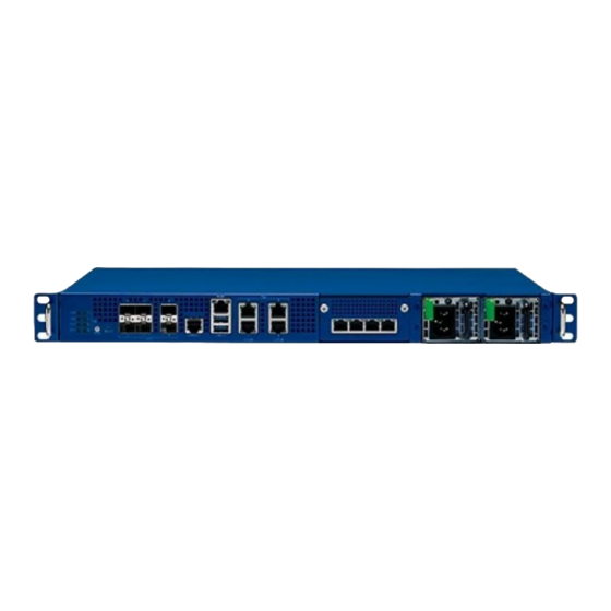
Page 17: Rear Panel
Chapter 1: Product Introduction Rear Panel Used to connect an analog VGA monitor. SMA Connectors Used to plug coaxial cable and optical fibers. Connectors Copyright © 2022 NEXCOM International Co., Ltd. All Rights Reserved. FTA5180 User Manual... -
Page 18: Chapter 2: Jumpers And Connectors
Static electricity can damage many of the electronic ▪ Use correct screws and do not over tighten screws. components. Humid environments tend to have less static electricity than Copyright © 2022 NEXCOM International Co., Ltd. All Rights Reserved. FTA5180 Series User Manual... -
Page 19: Jumper Settings
(on) and open (off). Two-Pin Jumpers: Open (Left) and Short (Right) Three-Pin Jumpers: Pins 1 and 2 are Short Copyright © 2022 NEXCOM International Co., Ltd. All Rights Reserved. FTA5180 Series User Manual... -
Page 20: Locations Of The Jumpers And Connectors
The figure below shows the location of the jumpers and connectors. FAN1 FAN2 IDV1 FAN3 FAN4 LCM1 JTAG1 FAN5 CN11 JP7 JP9 VGA1 POE1 BAT1 LED1 LED2 Copyright © 2022 NEXCOM International Co., Ltd. All Rights Reserved. FTA5180 Series User Manual... -
Page 21: Jumpers
Chapter 2: Jumpers and Connectors Jumpers RTC Clear Connector type: 1x3 3-pin header Connector location: JP3 Function Normal Clear CMOS Copyright © 2022 NEXCOM International Co., Ltd. All Rights Reserved. FTA5180 Series User Manual... -
Page 22: Connector Pin Definitions
Power LED PoE LED Connector location: LED1 Connector location: LED2 POE1 POE2 POE3 GPIO1 POE4 Definition Definition Definition Definition CPLD_PWR_LED CPLD_HDD_LED POE_LED1 POE_LED2 SW_SYS_LED CPLD_GPIO1_LED POE_LED3 POE_LED4 Copyright © 2022 NEXCOM International Co., Ltd. All Rights Reserved. FTA5180 Series User Manual... -
Page 23: Internal Connectors
Function POE_LED1 POE_LED2 SMB_DATA POE_LED3 POE_LED4 SMB_CLK P3V3 SMB_DAT_POE_R POE_INT_N SMB_CLK_POE_R POE_RST_N POE MAIN POK VPORT_NEG_10G_OUT4 P54V VPORT_NEG_10G_OUT3 P54V VPORT_NEG_10G_OUT2 P54V VPORT_NEG_10G_OUT1 VPORT_NEG_10G_OUT8 VPORT_NEG_10G_OUT5 VPORT_NEG_10G_OUT7 VPORT_NEG_10G_OUT6 Copyright © 2022 NEXCOM International Co., Ltd. All Rights Reserved. FTA5180 Series User Manual... -
Page 24: Lcm (Reserved)
Connector type: 1x4 4-pin header Connector type: 1x4 4-pin header Connector location: FAN1, FAN2, FAN3, FAN4, FAN5 Connector location: LCM1 Definition Definition Definition Definition P12V PWR_LCM SP_LCM_TXD TACH SP_LCM_RXD Copyright © 2022 NEXCOM International Co., Ltd. All Rights Reserved. FTA5180 Series User Manual... -
Page 25: Internal Power Connector
Connector type: 2x4 8-pin header Connector location: CON4 Connector location: CN9 Definition Definition Definition Definition P12V_AUX P12V_AUX P12V_AUX P12V_AUX P12V_AUX P12V_AUX P12V P12V P12V_AUX P5V_STBY P12V P12V Copyright © 2022 NEXCOM International Co., Ltd. All Rights Reserved. FTA5180 Series User Manual... -
Page 26: Internal Power Connector
Connector type: 2x10 20-pin header Connector location: CN11 Connector location: CN7 Definition Definition Definition Definition SMB-ALERT_A_CAB P12V SMB-ALERT_B_CAB P12V P12V SMB_PMBUS1_STBY_LVC3_R_SCL PRESENT_IN_A_CAB SMB_PMBUS1_STBY_LVC3_R_SDA PRESENT_IN_B_CAB PS_ON_R P3V3_AUX P3V3_AUX PW_OK_A_CAB PW_OK_B_CAB Copyright © 2022 NEXCOM International Co., Ltd. All Rights Reserved. FTA5180 Series User Manual... -
Page 27: Sys Rtc Holder
UART from CPLD (Reserved) Connector type: 1x3 3-pin header Connector type: 1x3 3-pin header Connector location: BAT1 Connector location: JP6 Function Function RTC_BAT PLD_PR20C RTC_BAT PLD_PR20D Copyright © 2022 NEXCOM International Co., Ltd. All Rights Reserved. FTA5180 Series User Manual... -
Page 28: Jtag Header From Cpld Or Bmc Select
BMC UART Debug Connector type: 1x4 4-pin header Connector type: 1x2 2-pin header Connector location: JP7 Connector location: JP9 Function Definition Definition JTAG_SEL P3V3_BMC BMC_CPLD_DEBUG_RXD BMC_CPLD_DEBUG_TXD Copyright © 2022 NEXCOM International Co., Ltd. All Rights Reserved. FTA5180 Series User Manual... -
Page 29: Idv Connector (For Debug)
PVNN_PCH RST_RSMRST_PCH_N PWRGD_PVCCIN_CPU FM_CPU_MSMI_LVT3_R_N P1V2_VDDQ PWRGD_PCH_PWROK PVCCIN_CPU PWRGD_PVNN_NAC P2V5_PVPP FM_CPU_ERR2_LVT3_N FM_CPU_CATERR_LVT3_R_N FM_CPU_PROCHOT_LATCH_ FM_CPU_ERR1_LVT3_N LVT3_R_N FM_CPU_THERMTRIP_LATCH_ FM_CPU_ERR0_LVT3_N LVT3_R_N PWRGD_DRAMPWRGD_R2 PVTT PWRGD_PS_PWROK_IDV FM_SLPS3_N FM_SLPS4_N SMB_SMLINK0_STBY_LVC3_MITI_ SMB_SMLINK0_STBY_LVC3_SCL PECI_CPU_PCH_BMC_R1 IDV_PWR_BUTTON_N Copyright © 2022 NEXCOM International Co., Ltd. All Rights Reserved. FTA5180 Series User Manual... -
Page 30: Cpld Jtag
Connector type: 1x16 16-pin header Connector location: JTAG1 Connector location: VGA1 Definition Definition Definition Definition P3V3_CPLD VGA_VCC JTAG_TCK_CPLD JTAG_TDO_CPLD SMB_BMC_DDC_SCL_R1 JTAG_TDI_CPLD JTAG_TMS_CPLD SMB_BMC_DDC_SDA_R1 V_BMC_GFX_REAR_VSYN_R3 V_BMC_GFX_REAR_HSYN_R3 10 V_BMC_GFX_REAR_BLU_R1 V_BMC_GFX_REAR_GRN_R1 V_BMC_GFX_REAR_RED_R1 Copyright © 2022 NEXCOM International Co., Ltd. All Rights Reserved. FTA5180 Series User Manual... -
Page 31: Xdp Connector (For Debug)
TP_XDP_UART_RX FM_DEBUG_EN_LVC3_N TP_PCH_DBG_PTI_D0 TRC_DFX_D0 TP_PCH_DBG_PTI_D1 TRC_PTI_CLK1 TRC_DFX_D1 TP_PCH_DBG_PTI_D2 TRC_DFX_D2 TP_PCH_DBG_PTI_D3 TRC_DFX_D3 TP_PCH_DBG_PTI_D4 TRC_DFX_D4 TP_PCH_DBG_PTI_D5 TRC_DFX_D5 TP_PCH_DBG_PTI_D6 TRC_DFX_D6 TP_PCH_DBG_PTI_D7 TRC_DFX_D7 TP_RSVD1_LTB_CONN TRC_DFX_D8 FM_GBE_SDP_TIMESYNC2_R TRC_DFX_D9 DBP_CPU_FBRK_N TRC_DFX_D10 XDP_PWR_BTN_N Copyright © 2022 NEXCOM International Co., Ltd. All Rights Reserved. FTA5180 Series User Manual... -
Page 32: Block Diagram
Reserved for LCM i225 i225 X710-TM4 Super IO 10Gx4 10Gx2 10Gx2 Microsemi 2.5Gx2 PD69208T4 RJ45 2xUSB3.0 Management Console port 6x SFP+ 4x RJ45 with PoE 90Wx4 10G LAN Copyright © 2022 NEXCOM International Co., Ltd. All Rights Reserved. FTA5180 Series User Manual... -
Page 33: Chapter 3: Bios Setup
BIOS is updated in the future. second, to make settings appropriate for the way you use the computer. To check for the latest updates and revisions, visit the NEXCOM website at When to Configure the BIOS www.nexcom.com.tw. -
Page 34: Default Configuration
Powering on the computer and immediately pressing allows you to enter Setup. Load optimized default values. Saves and exits the Setup program. Press <Enter> to enter the highlighted sub-menu Copyright © 2022 NEXCOM International Co., Ltd. All Rights Reserved. FTA5180 Series User Manual... - Page 35 When “” appears on the left of a particular field, it indicates that a submenu which contains additional options are available for that field. To display the submenu, move the highlight to that field and press Copyright © 2022 NEXCOM International Co., Ltd. All Rights Reserved. FTA5180 Series User Manual...
-
Page 36: Bios Setup Utility
+/-: Change Opt. F1: General Help System Time [14:36:31] F2: Previous Values F3: Optimized Defaults F4: Save & Exit ESC: Exit Version 2.22.1283. Copyright (C) 2022 AMI Copyright © 2022 NEXCOM International Co., Ltd. All Rights Reserved. FTA5180 Series User Manual... -
Page 37: Advanced
Enter: Select +/-: Change Opt. F1: General Help F2: Previous Values F3: Optimized Defaults F4: Save & Exit ESC: Exit Version 2.22.1283. Copyright (C) 2022 AMI Copyright © 2022 NEXCOM International Co., Ltd. All Rights Reserved. FTA5180 Series User Manual... - Page 38 Security Device. TCG EFI protocol and INT1A interface will not be available. SHA-1 PCR Bank Enables or disables SHA-1 PCR Bank. SHA256 PCR Bank Enables or disables SHA256 PCR Bank Copyright © 2022 NEXCOM International Co., Ltd. All Rights Reserved. FTA5180 Series User Manual...
- Page 39 Enables or disables the serial port. Change Settings Serial Port 1 Configuration Selects an optimal setting for the Super IO device. Configures the IO/IRQ settings of serial port 1. Copyright © 2022 NEXCOM International Co., Ltd. All Rights Reserved. FTA5180 Series User Manual...
- Page 40 Detects and displays the current fan1 to fan5 speed. Resolution Configures the legacy OS redirection resolution. P12V to PVNN_PCH Detects and displays the output voltages. Redirect After POST Enables or disables redirection after POST. Copyright © 2022 NEXCOM International Co., Ltd. All Rights Reserved. FTA5180 Series User Manual...
- Page 41 Bits Per Second Selects the serial port transmission speed. The speed must match the other side. Long or noisy lines may require a lower speed. Copyright © 2022 NEXCOM International Co., Ltd. All Rights Reserved. FTA5180 Series User Manual...
- Page 42 Enables or disables decoding of 64-bit devices in 4G address space. terminal data. SR-IOV Support Resolution 100x31 Enables or disables extended terminal resolution. Enables or disables SR-IOV support Putty Keypad Selects the Putty keyboard emulation type. Copyright © 2022 NEXCOM International Co., Ltd. All Rights Reserved. FTA5180 Series User Manual...
- Page 43 Configures the PCIe link speed. Selects the maximum TLP payload size of the PCI Express devices. Maximum Read Request Selects the maximum read request size of the PCI Express devices. Copyright © 2022 NEXCOM International Co., Ltd. All Rights Reserved. FTA5180 Series User Manual...
- Page 44 Disable Keeps USB devices available only for EFI applications. XHCI Hand-off This is a workaround for OSes that does not support XHCI hand-off. The XHCI ownership change should be claimed by the XHCI driver. Copyright © 2022 NEXCOM International Co., Ltd. All Rights Reserved. FTA5180 Series User Manual...
- Page 45 GA20 can be disabled using BIOS services. Always Do not allow disabling of GA20; this option is useful when any RT code is executed above 1MB. Copyright © 2022 NEXCOM International Co., Ltd. All Rights Reserved. FTA5180 Series User Manual...
- Page 46 Version 2.22.1283. Copyright (C) 2022 AMI PCH-IO Configuration PCH Parameters. Server ME Configuration Enters the Server ME Configuration submenu. IRC Firmware Configuration Enters the IRC Firmware Configuration submenu. Copyright © 2022 NEXCOM International Co., Ltd. All Rights Reserved. FTA5180 Series User Manual...
- Page 47 SATA Controller 3 device options settings. USB Configuration Enters the USB Configuration submenu. State After G3 Configures the power state when power is re-applied after a power failure (G3 state). Copyright © 2022 NEXCOM International Co., Ltd. All Rights Reserved. FTA5180 Series User Manual...
- Page 48 Enables or disables the USB port from reporting a device connection to the controller. Port 3 Enables or disables Serial ATA port 3. Hot Plug Enables or disables hot plugging feature on Serial ATA port 1 or 3. Copyright © 2022 NEXCOM International Co., Ltd. All Rights Reserved. FTA5180 Series User Manual...
- Page 49 F3: Optimized Defaults F4: Save & Exit F4: Save & Exit ESC: Exit ESC: Exit Version 2.22.1283. Copyright (C) 2022 AMI Version 2.22.1283. Copyright (C) 2022 AMI Copyright © 2022 NEXCOM International Co., Ltd. All Rights Reserved. FTA5180 Series User Manual...
- Page 50 Enters the Common RefCode Configuration submenu. Memory Configuration Enters the Memory Configuration submenu. IIO Configuration and Advanced Power Management Configuration Enters the IIO Configuration and Advanced Power Management Configuration submenu. Copyright © 2022 NEXCOM International Co., Ltd. All Rights Reserved. FTA5180 Series User Manual...
- Page 51 Enables or disables Check CPU BIST Result. Hardware Prefetcher Enables or disables the MLC streamer prefetcher. Adjacent Cache Prefetcher Enables or disables prefetching of adjacent cache lines. Copyright © 2022 NEXCOM International Co., Ltd. All Rights Reserved. FTA5180 Series User Manual...
- Page 52 Processor settings for the CPU on socket 0. Provides the option to enable or disable all cores. 0 means enable all cores. FFFFFFF means disable all cores. Copyright © 2022 NEXCOM International Co., Ltd. All Rights Reserved. FTA5180 Series User Manual...
- Page 53 MMCFG Size Memory Frequency Select MMCFG size. Configures the maximum frequency of the memory. Do not select Reserved. Virtual Numa Enables or disables Non-Uniform Memory Access support. Copyright © 2022 NEXCOM International Co., Ltd. All Rights Reserved. FTA5180 Series User Manual...
- Page 54 Enters the Socket0 Configuration submenu. IOAT Configuration Enters the IOAT Configuration submenu. Intel. VT for Directed I/O (VT-d) Enters the Intel VT for Directed I/O (VT-d) submenu. ® Copyright © 2022 NEXCOM International Co., Ltd. All Rights Reserved. FTA5180 Series User Manual...
- Page 55 Configures the link speed for the PCIe port. PCI-E Port DeEmphasis Configures the de-emphasis control for the PCIe port. DMI Port MPSS Configures the DMI Port MPSS. Copyright © 2022 NEXCOM International Co., Ltd. All Rights Reserved. FTA5180 Series User Manual...
- Page 56 EXP port if there is no device or errors on that device and the device is not HP capable. Disable is used to disable the port and hide its CFG space. Link Speed Configures the link speed for the PCIe port. Copyright © 2022 NEXCOM International Co., Ltd. All Rights Reserved. FTA5180 Series User Manual...
- Page 57 Configures the link speed for the PCIe port. PCI-E Port DeEmphasis Configures the de-emphasis control for the PCIe port. PCI-E Port MPSS Configures the PCI-e Port MPSS. Copyright © 2022 NEXCOM International Co., Ltd. All Rights Reserved. FTA5180 Series User Manual...
- Page 58 Version 2.22.1283. Copyright (C) 2022 AMI Version 2.22.1283. Copyright (C) 2022 AMI Enables or disables DMA. No Snoop Enables or disables No Snoop function for each CB device. Copyright © 2022 NEXCOM International Co., Ltd. All Rights Reserved. FTA5180 Series User Manual...
- Page 59 I/O device assignment to VMM through DMAR ACPI tables. Hardware PM State Control Interrupt Remapping Enters the Hardware PM State Control submenu Configures Interrupt Remapping. X2APIC Opt Out Enables or disables X2APIC mode. Copyright © 2022 NEXCOM International Co., Ltd. All Rights Reserved. FTA5180 Series User Manual...
- Page 60 Hardware chooses a P-state based on OS Request. (Legacy P-States). Native Mode Hardware chooses a P-state based on OS guidance. Out of Band Mode Hardware autonomously chooses a P-state (no OS guidance). Copyright © 2022 NEXCOM International Co., Ltd. All Rights Reserved. FTA5180 Series User Manual...
- Page 61 Configures the options for erasing SEL. When SEL is Full Configures the action to perform when SEL is full. Log EFI Status Codes Configures the options for logging EFI status codes. Copyright © 2022 NEXCOM International Co., Ltd. All Rights Reserved. FTA5180 Series User Manual...
- Page 62 BMC). Unspecified option will not modify any BMC network parameters When Log is Full during BIOS phase. Configures the action to perform when log is full Copyright © 2022 NEXCOM International Co., Ltd. All Rights Reserved. FTA5180 Series User Manual...
- Page 63 Version 2.22.1283. Copyright (C) 2022 AMI Version 2.22.1283. Copyright (C) 2022 AMI IPv6 Support (LAN Channel 1) Enables or disables IPv6 support for LAN channel 1. Copyright © 2022 NEXCOM International Co., Ltd. All Rights Reserved. FTA5180 Series User Manual...
- Page 64 Version 2.22.1283. Copyright (C) 2022 AMI VLAN Support Displays system event log information including date, time and sensor type. Enables to specify the 802.1q VLAN ID. Copyright © 2022 NEXCOM International Co., Ltd. All Rights Reserved. FTA5180 Series User Manual...
- Page 65 Channel No and User Privilege Limit Option to delete a user. Configures the BMC channel number and account access rights. Change User Settings Option to change user settings. Copyright © 2022 NEXCOM International Co., Ltd. All Rights Reserved. FTA5180 Series User Manual...
- Page 66 Reconfigures a new password for the account. User Access Enables or disables this account. Channel No and User Privilege Limit Reconfigures the BMC channel number and account access rights. Copyright © 2022 NEXCOM International Co., Ltd. All Rights Reserved. FTA5180 Series User Manual...
-
Page 67: Security
NumLock on wherein the function of the numeric keypad is the number keys. When set to Off, the function of the numeric keypad is the arrow keys. Copyright © 2022 NEXCOM International Co., Ltd. All Rights Reserved. FTA5180 Series User Manual... -
Page 68: Save & Exit
<Enter>. You may be prompted to confirm again before exiting. Restore Defaults To restore the BIOS to default settings, select this field then press <Enter>. A dialog box will appear. Confirm by selecting Yes. Copyright © 2022 NEXCOM International Co., Ltd. All Rights Reserved. FTA5180 Series User Manual... - Page 69 <Enter>. Launch EFI Shell from filesystem device To launch EFI shell from a filesystem device, select this field and press <Enter>. Copyright © 2022 NEXCOM International Co., Ltd. All Rights Reserved. FTA5180 Series User Manual...
Need help?
Do you have a question about the FTA 5180 Series and is the answer not in the manual?
Questions and answers