
Related Manuals for Nexcom DTA1376 Series


Summary of Contents for Nexcom DTA1376 Series
- Page 1 NEXCOM International Co., Ltd. Network and Communication Solutions Desktop Telecom Appliance DTA1376 Series User Manual NEXCOM International Co., Ltd. www.nexcom.com Published October 2022...
-
Page 2: Table Of Contents
Hardware Specifications ................2 Internal Connectors ................17 Knowing Your DTA1376/DTA1376A ............3 Fan Connector ................17 Front Panel ..................3 RTC Battery Holder .................17 Rear Panel ...................4 SD Card Signal Connector ..............18 Copyright © 2022 NEXCOM International Co., Ltd. All Rights Reserved. DTA1376 Series User Manual... - Page 3 Operating System Information ..............29 Logging into the System...............29 Mapping the Network Ports ..............29 Installing the Software Package .............30 ip_forward Testing ................30 Turning Off the DTA1376/DTA1376A ............30 Copyright © 2022 NEXCOM International Co., Ltd. All Rights Reserved. DTA1376 Series User Manual...
-
Page 4: Preface
No describes how to keep the system CE compliant. part of this manual may be reproduced, copied, translated or transmitted in any form or by any means without the prior written consent from NEXCOM Declaration of Conformity International Co., Ltd. -
Page 5: Rohs Compliance
0.1% or 1,000ppm, and Polybrominated diphenyl Ethers (PBDE) < 0.1% or 1,000ppm. In order to meet the RoHS compliant directives, NEXCOM has established an engineering and manufacturing task force in to implement the introduction of green products. The task force will ensure that we follow the standard... -
Page 6: Warranty And Rma
“NEXCOM RMA Service Form” for the RMA number apply process. ▪ If RMA goods can not be repaired, NEXCOM will return it to the customer without any charge. ▪ Customers can send back the faulty products with or without accessories (manuals, cable, etc.) and any components from the card, such as CPU... - Page 7 ESD workstation. If no such station is available, you can provide some ESD protection by wearing an antistatic wrist strap and attaching it to a metal part of the computer chassis. Copyright © 2022 NEXCOM International Co., Ltd. All Rights Reserved. DTA1376 Series User Manual...
-
Page 8: Safety Information
There is a danger of explosion if battery is incorrectly replaced. Replace only with the same or equivalent type recommended by the manufacturer. Discard used batteries according to the manufacturer’s instructions. viii Copyright © 2022 NEXCOM International Co., Ltd. All Rights Reserved. DTA1376 Series User Manual... -
Page 9: Safety Precautions
20. Use certified and rated Laser Class I for Optical Transceiver product. 13. Never open the equipment. For safety reasons, the equipment should be opened only by skilled person. Copyright © 2022 NEXCOM International Co., Ltd. All Rights Reserved. DTA1376 Series User Manual... -
Page 10: Technical Support And Assistance
Preface Technical Support and Assistance Conventions Used in this Manual 1. For the most updated information of NEXCOM products, visit NEXCOM’s Warning: website at www.nexcom.com. Information about certain situations, which if not observed, can cause personal injury. This will prevent injury to yourself 2. -
Page 11: Global Service Contact Information
Tel: +886-2-8226-7786 Tel: +886-2-8976-3077 Beitun District, Fax: +886-2-8226-7782 Email: sales@diviotec.com Taichung City, 406, Taiwan, R.O.C. Email: services@tmrtek.com www.diviotec.com Tel: +886-4-2249-1179 www.tmrtek.com Fax: +886-4-2249-1172 Email: jacobhuang@nexaiot.com www.nexaiot.com Copyright © 2022 NEXCOM International Co., Ltd. All Rights Reserved. DTA1376 Series User Manual... - Page 12 9F, Tamachi Hara Bldg., LongGang District, 4-11-5, Shiba Minato-ku, ShenZhen, 518112, China Tokyo, 108-0014, Japan Tel: +86-755-8364-7768 Tel: +81-3-5419-7830 Fax: +86-755-8364-7738 Fax: +81-3-5419-7832 Email: steveyang@nexcom.com.tw Email: sales@nexcom-jp.com www.nexcom.cn www.nexcom-jp.com Copyright © 2022 NEXCOM International Co., Ltd. All Rights Reserved. DTA1376 Series User Manual...
-
Page 13: Package Contents
Preface Package Contents Before continuing, verify that the DTA1376 series package that you received is complete. Your DTA1376 series package should have all the items listed in the table below. Item Part Number Name 10TA0137600X0 / DTA1376 / DTA1376A 5044440031X00... -
Page 14: Ordering Information
Preface Ordering Information The following below provides ordering information for DTA1376 series. DTA1376 (P/N: 10TA0137600X0) Layerscape LS1046A processor, SoC, BGA type, 4 Cortex-A72 ® ® cores, 1.8GHz, 7 x 1GbE RJ45 ports DTA1376A (P/N: TBD) ® Layerscape ® LS1046A processor, SoC, BGA type, 4 Cortex-A72 cores, 1.8GHz, 7 x 1GbE RJ45 ports, with PoE++ PD function... -
Page 15: Chapter 1: Product Introduction
▪ 1 x DDR4-2133 SO-DIMM ECC socket, up to 16GB ▪ PoE++ PD (DTA1376A only) ▪ 1 x M.2 2242 NVMe SSD ▪ 7 x 1GbE RJ45 ports Copyright © 2022 NEXCOM International Co., Ltd. All Rights Reserved. DTA1376 Series User Manual... -
Page 16: Hardware Specifications
▪ 6 x SMA connectors (sides: 4 x for 4G LTE/5G antennas, back: 2 x forWi-Fi ▪ NXP ® Layerscape ® SDK 20.04-NEXCOM DTA1376 revision 5 antennas) ▪ 7 x 1GbE RJ45 ports Copyright © 2022 NEXCOM International Co., Ltd. All Rights Reserved. DTA1376 Series User Manual... -
Page 17: Knowing Your Dta1376/Dta1376A
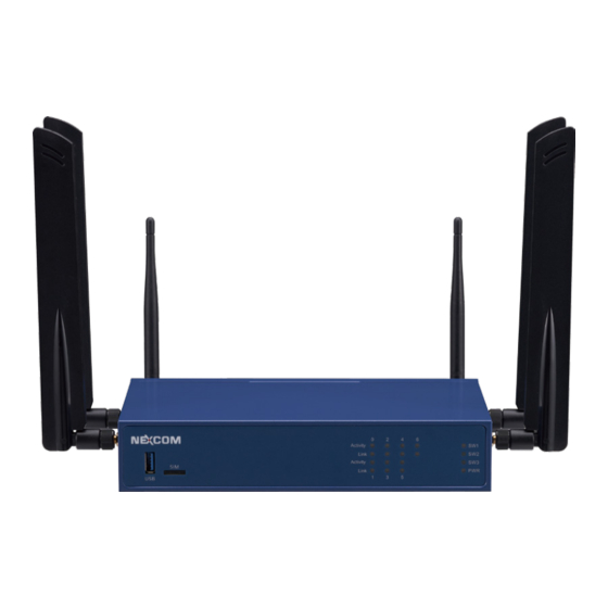
Three programmable LEDs (SW1, SW2, and SW3) and LED for power status (PWR) of the system. USB 3.0 SIM Slot LAN LED SW1/SW2/SW3/ Indicators PWR LED Indicators Copyright © 2022 NEXCOM International Co., Ltd. All Rights Reserved. DTA1376 Series User Manual... -
Page 18: Rear Panel
Power Button Press to power on or off the system. 12V DC LAN0 to LAN6 Reset Power Input Copper Ports Button Button RJ45 Console USB 3.0 Copyright © 2022 NEXCOM International Co., Ltd. All Rights Reserved. DTA1376 Series User Manual... -
Page 19: Chapter 2: Jumpers And Connectors
Static electricity can damage many of the electronic ▪ Use correct screws and do not over tighten screws. components. Humid environments tend to have less static electricity than Copyright © 2022 NEXCOM International Co., Ltd. All Rights Reserved. DTA1376 Series User Manual... -
Page 20: Jumper Settings
(on) and open (off). Two-Pin Jumpers: Open (Left) and Short (Right) Three-Pin Jumpers: Pins 1 and 2 are Short Copyright © 2022 NEXCOM International Co., Ltd. All Rights Reserved. DTA1376 Series User Manual... -
Page 21: Locations Of The Jumpers And Connectors
Locations of the Jumpers and Connectors The figure below shows the location of the jumpers and connectors. DIMM1 LED1 LED2 LED3 LED4 LED5 FAN1 CPLD_JP1 BAT1 Copyright © 2022 NEXCOM International Co., Ltd. All Rights Reserved. DTA1376 Series User Manual... -
Page 22: Jumpers
1 2 3 4 5 6 7 8 Function Definition Definition BOOT FROM SD CARD SW_RCW_SRC7 SW_RCW_SRC3 BOOT FROM eMMC SW_RCW_SRC6 SW_RCW_SRC2 SW_RCW_SRC5 SW_RCW_SRC1 SW_RCW_SRC4 SW_RCW_SRC0 Copyright © 2022 NEXCOM International Co., Ltd. All Rights Reserved. DTA1376 Series User Manual... -
Page 23: Connector Pin Definitions
Chapter 2: Jumpers and Connectors Connector Pin Definitions External I/O Interfaces 12V DC Input System Reset Button Connector location: CN1 Connector location: SW2 Definition Definition RESET_BUTTON P12V_IN Copyright © 2022 NEXCOM International Co., Ltd. All Rights Reserved. DTA1376 Series User Manual... -
Page 24: Power Button
Chapter 2: Jumpers and Connectors Power Button Nano SIM Card Connector Connector location: SW3 Connector location: CN5 Definition Definition Definition PON_CPLD_BTN Copyright © 2022 NEXCOM International Co., Ltd. All Rights Reserved. DTA1376 Series User Manual... -
Page 25: Usb 3.0 Port (Front Panel)
USB2_DN USB3_TX_DP USB2_DN SP_DTR0_R USB2_DP GND_chassis USB2_DP SP_TXD0_R GND_chassis SP_DCD0_R USB3_RX_DN GND_chassis USB3_RX_DN USB3_RX_DP USB3_RX_DP SP_RXD0_R SP_DSR0_R USB3_TX_DN SP_CTS0_R USB3_TX_DP GND_chassis GND_chassis GND_chassis GND_chassis GND_chassis GND_chassis Copyright © 2022 NEXCOM International Co., Ltd. All Rights Reserved. DTA1376 Series User Manual... -
Page 26: Lan 1 And Lan 2 Ports
Steady Orange 100Mbps network link VCC_A VCC_B 10Mbps or no link GND_A GND_B V3P3 V3P3 1545_LAN2_LED_ACT 1545_LAN1_LED_ACT 1545_LAN2_LED_1000M 1545_LAN1_LED_1000M 1545_LAN2_LED_100M 1545_LAN1_LED_100M GND_chassis GND_chassis GND_chassis GND_chassis GND_chassis GND_chassis Copyright © 2022 NEXCOM International Co., Ltd. All Rights Reserved. DTA1376 Series User Manual... -
Page 27: Lan 3 And Lan 4 Ports
Steady Orange 100Mbps network link VCC_A VCC_B 10Mbps or no link GND_A GND_B V3P3 V3P3 1545_LAN4_LED_ACT 1545_LAN3_LED_ACT 1545_LAN4_LED_1000M 1545_LAN3_LED_1000M 1545_LAN4_LED_100M 1545_LAN3_LED_100M GND_chassis GND_chassis GND_chassis GND_chassis GND_chassis GND_chassis Copyright © 2022 NEXCOM International Co., Ltd. All Rights Reserved. DTA1376 Series User Manual... -
Page 28: Lan 5 And Lan 6 Ports
Steady Orange 100Mbps network link VCC_A VCC_B 10Mbps or no link GND_A GND_B V3P3 V3P3 1G_LAN6_LED_ACT 1G_LAN5_LED_ACT 1G_LAN6_LED_1000M 1G_LAN5_LED_1000M 1G_LAN6_LED_100M 1G_LAN5_LED_100M GND_chassis GND_chassis GND_chassis GND_chassis GND_chassis GND_chassis Copyright © 2022 NEXCOM International Co., Ltd. All Rights Reserved. DTA1376 Series User Manual... -
Page 29: Lan 0 Port
Steady Green 1G network link PB_CT 1G_LAN1_LED_1000M Steady Orange 100Mbps network link PB_CT 1G_LAN1_LED_ACT 10Mbps or no link PB_MDI3P V3P3 PB_MDI3N GND_chassis PB_MDI0N GND_chassis PB_MDI0P PB_CT Copyright © 2022 NEXCOM International Co., Ltd. All Rights Reserved. DTA1376 Series User Manual... -
Page 30: Led Indicators
Ethernet connected Green User define LEDs Power down Blinking Data transferring Green User define Power down Green User define Steady Standby (Power) Green Steady Power on Copyright © 2022 NEXCOM International Co., Ltd. All Rights Reserved. DTA1376 Series User Manual... -
Page 31: Internal Connectors
Fan Connector RTC Battery Holder Connector type: 1x4 4-pin wafer Connector type: 1x2 2-pin header Connector location: FAN1 Connector location: BAT1 Definition Definition 3V_BATT FAN1_IN FAN1_PWM_R Copyright © 2022 NEXCOM International Co., Ltd. All Rights Reserved. DTA1376 Series User Manual... -
Page 32: Sd Card Signal Connector
Connector type: 1x6 6-pin header Connector type: 1x9 9-pin header Connector location: CPLD_JP1 Connector location: JP2 Definition Definition Definition Definition V3P3_VSB JTAG_CPLD_TDO DATA3 JTAG_CPLD_TDI DATA2 JTAG_CPLD_TCK JTAG_CPLD_TMS DATA0 DATA1 CD_B Copyright © 2022 NEXCOM International Co., Ltd. All Rights Reserved. DTA1376 Series User Manual... -
Page 33: M.2 M-Key (2242) For Nvme Ssd
M KEY M KEY SD2_TX2_N M KEY SD2_RX3_N SD2_TX2_P NGFF_SUSCLK P3V3_MKEY SD2_RX3_P NGFF_PERST_N P3V3_MKEY P3V3_MKEY SSD_CLKREQ# PCIE3_REFCLK_S_N P3V3_MKEY P3V3_MKEY SD2_TX3_N PCIE3_REFCLK_S_P P3V3_MKEY P3V3_MKEY SD2_TX3_P NGFF_DEVSLP(Always Low) Copyright © 2022 NEXCOM International Co., Ltd. All Rights Reserved. DTA1376 Series User Manual... -
Page 34: M.2 B-Key (3042/3052) For 4G Lte/5G Modem Module
B KEY SIM_CLK P3V3_BKEY B KEY BKEY_CLKREQ_N B KEY SIM_DATA PCIE1_REFCLK_S_N P3V3_BKEY B KEY BKEY_PEWAKE# B KEY SIM_PWR BKEY_PEWAKE# P3V3_BKEY B KEY TEST_POINT M2_BKEY_CONFIG2 B KEY 5G_COLAY_38 Copyright © 2022 NEXCOM International Co., Ltd. All Rights Reserved. DTA1376 Series User Manual... -
Page 35: Mini-Pcie Connector For Wi-Fi 5 Module
P3V3_MNPE P3V3_MNPE P3V3_MNPE P3V3_MNPE SMBUS_EKEY_CLK SD2_TX1_N P3V3_MNPE SMBUS_EKEY_DATA V5P0 CLKREQ_MNPE_N W_DISABLE_MNPE_N SD2_TX1_P P3V3_MNPE V5P0 SOC_PLTRST_N MNPE_RX_DN0_R TEST_POINT V5P0 PCIE2_REFCLK_S_N P3V3_MNPE MNPE_RX_DP0_R TEST_POINT V5P0 PCIE2_REFCLK_S_P P3V3_MNPE P3V3_MNPE Copyright © 2022 NEXCOM International Co., Ltd. All Rights Reserved. DTA1376 Series User Manual... -
Page 36: Block Diagram
Chapter 2: Jumpers and Connectors Block Diagram Copyright © 2022 NEXCOM International Co., Ltd. All Rights Reserved. DTA1376 Series User Manual... -
Page 37: Chapter 3: System Setup
1. The screws on the bottom and sides of the cover are used to secure the cover to the chassis. Remove these screws and put them in a safe place for later use. Screws on the bottom Screws on the sides Copyright © 2022 NEXCOM International Co., Ltd. All Rights Reserved. DTA1376 Series User Manual... - Page 38 To prevent this, place the cover past ahead of the acetate tape before sliding it back. Refer to the images below for more information. Correct way Acetate tape Incorrect way Copyright © 2022 NEXCOM International Co., Ltd. All Rights Reserved. DTA1376 Series User Manual...
-
Page 39: Installing A So-Dimm Memory Module
3. Push the module down until the clips on both sides of the socket lock into position. You will hear a distinctive “click” sound, indicating the module is correctly locked into position. SO-DIMM Socket Memory Module Copyright © 2022 NEXCOM International Co., Ltd. All Rights Reserved. DTA1376 Series User Manual... -
Page 40: Installing A M.2 Module
Push the M.2 module down and fasten an M.2 mounting screw into the mounting hole to secure the module. M.2 slot M.2 mounting hole Secure the M.2 module Copyright © 2022 NEXCOM International Co., Ltd. All Rights Reserved. DTA1376 Series User Manual... -
Page 41: Installing A Wi-Fi Module
Push the Wi-Fi module down and fasten a Wi-Fi mounting screw into the mounting hole to secure the module. Wi-Fi slot Secure the Wi-Fi module Copyright © 2022 NEXCOM International Co., Ltd. All Rights Reserved. DTA1376 Series User Manual... -
Page 42: Installing A 4G Lte/5G Modem Module
M.2 mounting screw into the mounting hole to secure the module. M.2 mounting hole M.2 slot Secure the module 4G LTE/5G modem module Copyright © 2022 NEXCOM International Co., Ltd. All Rights Reserved. DTA1376 Series User Manual... -
Page 43: Chapter 4: System Configuration
PC. The UART Baud rate setting is 115200-8-N-1 and no flow control. Log in to Ubuntu using the installed terminal software after powering on the DTA1376/DTA1376A. By default, the username and password both are "root". Copyright © 2022 NEXCOM International Co., Ltd. All Rights Reserved. DTA1376 Series User Manual... -
Page 44: Installing The Software Package
Step1. dhclient fm1-mac6 Step2. apt update Step3. apt install specified_package_name ip_forward Testing To do the “ip_forward” testing, the command should be as follows: “/etc/sysctl.conf” to set “net.ipv4.ip_forward=1”. Copyright © 2022 NEXCOM International Co., Ltd. All Rights Reserved. DTA1376 Series User Manual...
Need help?
Do you have a question about the DTA1376 Series and is the answer not in the manual?
Questions and answers