
Related Manuals for Nexcom Neu-X300 Series


Summary of Contents for Nexcom Neu-X300 Series
- Page 1 NEXCOM International Co., Ltd. Intelligent Platform & Services Business Unit Edge Computing System Neu-X300 Series User Manual NEXCOM International Co., Ltd. www.nexcom.com Published July 2020...
-
Page 2: Table Of Contents
RoHS Compliance ................... v Precautions ....................7 Warranty and RMA ................vi Jumper Settings ..................8 Safety Information ................viii Locations of the Jumpers and Connectors for the Neu-X300 Series ..9 Installation Recommendations ...............viii Top View .....................9 Safety Precautions .................. ix Bottom View ..................10 Technical Support and Assistance ............ - Page 3 Installing an M.2 M-Key SSD Module (M-Key 2280) ......32 Installing a SO-DIMM Memory Module ..........34 Installing a Wi-Fi Module (M.2 E-Key Slot) ..........35 Installing a CPU ..................38 Wall Mounting Instructions ..............41 Copyright © 2020 NEXCOM International Co., Ltd. All Rights Reserved. Neu-X300 Series User Manual...
-
Page 4: Preface
No describes how to keep the system CE compliant. part of this manual may be reproduced, copied, translated or transmitted in any form or by any means without the prior written consent from NEXCOM Declaration of Conformity International Co., Ltd. -
Page 5: Rohs Compliance
(Cr6+) < 0.1% or 1,000ppm, Polybrominated biphenyls (PBB) < 0.1% or 1,000ppm, and Polybrominated diphenyl Ethers (PBDE) < 0.1% or 1,000ppm. In order to meet the RoHS compliant directives, NEXCOM has established an engineering and manufacturing task force to implement the introduction of green products. -
Page 6: Warranty And Rma
“NEXCOM RMA Service Form” for the RMA number apply process. ▪ If RMA goods can not be repaired, NEXCOM will return it to the customer without any charge. ▪ Customers can send back the faulty products with or without accessories (manuals, cable, etc.) and any components from the card, such as CPU... - Page 7 ESD workstation. If no such station is available, you can provide some ESD protection by wearing an antistatic wrist strap and attaching it to a metal part of the computer chassis. Copyright © 2020 NEXCOM International Co., Ltd. All Rights Reserved. Neu-X300 Series User Manual...
-
Page 8: Safety Information
There is a danger of explosion if battery is incorrectly replaced. Replace only with the same or equivalent type recommended by the manufacturer. Discard used batteries according to the manufacturer’s instructions. viii Copyright © 2020 NEXCOM International Co., Ltd. All Rights Reserved. Neu-X300 Series User Manual... -
Page 9: Safety Precautions
UL/IEC 60950-1 and/or UL/IEC 62368-1. If further assistance is needed, please contact NEXCOM International Co., Ltd. (UL file owner or brand owner) for further information. Copyright © 2020 NEXCOM International Co., Ltd. All Rights Reserved. -
Page 10: Technical Support And Assistance
Preface Technical Support and Assistance Conventions Used in this Manual 1. For the most updated information of NEXCOM products, visit NEXCOM’s Warning: website at www.nexcom.com. Information about certain situations, which if not observed, can cause personal injury. This will prevent injury to yourself 2. -
Page 11: Global Service Contact Information
16F, No.250, Sec. 2, Chongde Rd., Beijing, 100094, China Beitun Dist., Tel: +86-10-5704-2680 Taichung City 406, R.O.C. Fax: +86-10-5704-2681 Tel: +886-4-2249-1179 Email: sales@nexcom.cn Fax: +886-4-2249-1172 www.nexcom.cn Email: sales@nexcom.com.tw www.nexcom.com.tw Copyright © 2020 NEXCOM International Co., Ltd. All Rights Reserved. Neu-X300 Series User Manual... - Page 12 Tokyo, 108-0014, Japan No. 609, Yunlin East Rd., Tel: +81-3-5419-7830 Shanghai, 200062, China Fax: +81-3-5419-7832 Tel: +86-21-5278-5868 Email: sales@nexcom-jp.com Fax: +86-21-3251-6358 www.nexcom-jp.com Email: renwang@nexcom.com.tw www.nexcom.cn Copyright © 2020 NEXCOM International Co., Ltd. All Rights Reserved. Neu-X300 Series User Manual...
-
Page 13: Package Contents
Thermal Pad NDiS B533 VER:A EAPUS 25x25x0.2mm Power Adapter FSP:FSP096-AHBN2 (N090001) 96W DC12V/8A DC 7400096006X00 Power Adapter Plug 4 Pin Power Molding Type 7400096007X00 Power Adapter Power Adapter FSP:FSP096-AHAN3 96W 12V/8A xiii Copyright © 2020 NEXCOM International Co., Ltd. All Rights Reserved. Neu-X300 Series User Manual... -
Page 14: Ordering Information
Core™ processor slim and fanless system with PCH Q370 ® Neu-X300-H370 PCB Ver.B (P/N: 10W10X30001X4) 8th generation Intel ® Core™ processor slim and fanless system with PCH H310 Copyright © 2020 NEXCOM International Co., Ltd. All Rights Reserved. Neu-X300 Series User Manual... -
Page 15: Chapter 1: Product Introduction
▪ Storage M.2 M Key 2280 ▪ Support Intel vPro technology ® ▪ Dual DDR4 SO-DIMM Neu-X300-Q370 ▪ Onboard TPM 2.0 IC ▪ Fanless design Neu-X300-H310 Copyright © 2020 NEXCOM International Co., Ltd. All Rights Reserved. Neu-X300 Series User Manual... -
Page 16: Hardware Specifications
▪ 190mm (L) x 200mm (W) x 54.4mm (H) ▪ 1 x 12V DC input, 4-pin DC jack ▪ 1 x Audio out Operating System ▪ Windows 10 64-bit/Linux Copyright © 2020 NEXCOM International Co., Ltd. All Rights Reserved. Neu-X300 Series User Manual... -
Page 17: Physical Features
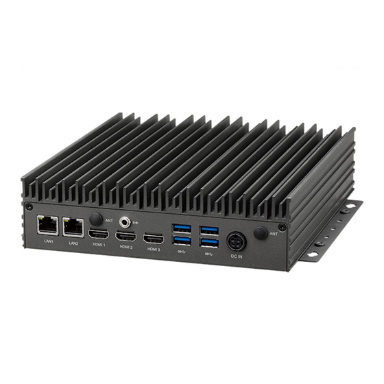
Neu-X300-Q370 Front Panel Neu-X300-Q370 Rear Panel Storage LED Antenna Hole Line-out Antenna Hole Power Button COM 1 LAN1 LAN2 USB 3.0 HDMI1 HDMI2 HDMI3 DC Input Copyright © 2020 NEXCOM International Co., Ltd. All Rights Reserved. Neu-X300 Series User Manual... -
Page 18: Neu-X300-H310 Front Panel
Chapter 1: Product Introduction Neu-X300-H310 Front Panel Neu-X300-H310 Rear Panel Storage LED Antenna Hole Line-out Antenna Hole Power Button COM 1 LAN1 LAN2 USB 3.0 HDMI1 HDMI2 DC Input Copyright © 2020 NEXCOM International Co., Ltd. All Rights Reserved. Neu-X300 Series User Manual... -
Page 19: Mechanical Dimensions
Chapter 1: Product Introduction Mechanical Dimensions Neu-X300-Q370 Copyright © 2020 NEXCOM International Co., Ltd. All Rights Reserved. Neu-X300 Series User Manual... -
Page 20: Neu-X300-H310
Chapter 1: Product Introduction Neu-X300-H310 Copyright © 2020 NEXCOM International Co., Ltd. All Rights Reserved. Neu-X300 Series User Manual... -
Page 21: Chapter 2: Jumpers And Connectors
Static electricity can damage many of the electronic ▪ Use correct screws and do not over tighten screws. components. Humid environments tend to have less static electricity than Copyright © 2020 NEXCOM International Co., Ltd. All Rights Reserved. Neu-X300 Series User Manual... -
Page 22: Jumper Settings
(on) and open (off). Two-Pin Jumpers: Open (Left) and Short (Right) Three-Pin Jumpers: Pins 1 and 2 are Short Copyright © 2020 NEXCOM International Co., Ltd. All Rights Reserved. Neu-X300 Series User Manual... -
Page 23: Locations Of The Jumpers And Connectors For The Neu-X300 Series
Chapter 2: Jumpers and Connectors Locations of the Jumpers and Connectors for the Neu-X300 Series The figure below is the top and bottom view of the mainboard used in the Neu-X300 series. It shows the locations of the jumpers and connectors. ATX_AT BLT_PWM... -
Page 24: Bottom View
Chapter 2: Jumpers and Connectors Bottom View Copyright © 2020 NEXCOM International Co., Ltd. All Rights Reserved. Neu-X300 Series User Manual... -
Page 25: Jumpers & Dip Switches
Connector location: CLRTC Settings Settings 1-2 On ATX Mode 1-2 On Normal 2-3 On AT Mode 2-3 On Clear CMOS 1-2 On: default 1-2 On: default Copyright © 2020 NEXCOM International Co., Ltd. All Rights Reserved. Neu-X300 Series User Manual... -
Page 26: Lvds Panel Voltage Select
Connector type: 1x3 3-pin header, 2.0mm pitch Connector location: LVDS_PWR Connector location: BLT_PWM Settings Settings 1-2 On 3.3V 1-2 On 3.3V 2-3 On 2-3 On 1-2 On: default 1-2 On: default Copyright © 2020 NEXCOM International Co., Ltd. All Rights Reserved. Neu-X300 Series User Manual... -
Page 27: Me Flash Descriptor Security Override
Chapter 2: Jumpers and Connectors ME Flash Descriptor Security Override Connector type: 1x3 3-pin header, 2.0mm pitch Connector location: ME_LOCK Settings 1-2 On Lock 2-3 On Unlock 1-2 On: default Copyright © 2020 NEXCOM International Co., Ltd. All Rights Reserved. Neu-X300 Series User Manual... -
Page 28: Lvds Resolution Select
1680 x 1050 8-bit Dual Port 1101 1600 x 1200 8-bit Dual Port 1110 1920 x 1080 8-bit Dual Port 1111 1920 x 1200 8-bit Dual Port Copyright © 2020 NEXCOM International Co., Ltd. All Rights Reserved. Neu-X300 Series User Manual... -
Page 29: Connector Pin Definitions
10Mbps or no link Definition Definition Definition Definition TX2P MDI_0P MDI_0N TX2N TX1P MDI_1P MDI_1N TX1N TX0P MDI_2P MDI_2N TX0N CLKP MDI_3P MDI_3N CLKN +3VSB ACTLED# LINK100# LINK1000# Copyright © 2020 NEXCOM International Co., Ltd. All Rights Reserved. Neu-X300 Series User Manual... -
Page 30: Usb 3.0 Ports
Connector location: CN1 Connector location: USB3_P12 and USB3_P34 Definition Definition Definition Definition USB2_2N +12VSUS +12VSUS USB2_2P USB3_RX2N USB3_RX2P CGND USB3_TX2N USB3_TX2P USB2_1N USB2_1P USB3_RX1N USB3_RX1P USB3_TX1N USB3_TX1P Copyright © 2020 NEXCOM International Co., Ltd. All Rights Reserved. Neu-X300 Series User Manual... -
Page 31: Com1 Db9 Male Connector
Chapter 2: Jumpers and Connectors COM1 DB9 Male Connector Connector type: DB-9 port, 9-pin D-Sub Connector location: COM1 Definition Definition Copyright © 2020 NEXCOM International Co., Ltd. All Rights Reserved. Neu-X300 Series User Manual... -
Page 32: Internal Connectors
Connector type: 1x7 7-pin header JST, 2.5mm pitch Connector type: 1x2 2-pin header, 2.54mm pitch Connector location: INV Connector location: RESET Definition Definition Definition RESET# Backlight Control Backlight Enable Copyright © 2020 NEXCOM International Co., Ltd. All Rights Reserved. Neu-X300 Series User Manual... -
Page 33: Led Connector
Connector type: 1x4 4-pin header, 1.25mm pitch Connector location: LED_CON Connector location: LINE_OUT Definition Definition Definition Definition HDD_LED- HDD_LED+ LOUT_L Standby LED LOUT_JD LOUT_R PWR LED Copyright © 2020 NEXCOM International Co., Ltd. All Rights Reserved. Neu-X300 Series User Manual... -
Page 34: Mic-In Connector
Connector type: 1x4 4-pin header, 1.25mm pitch Connector type: 1x2 2-pin header JST, 2.0mm pitch Connector location: MIC Connector location: J7 Definition Definition Definition MIC_L PWRBTN# MIC_JD MIC_R Copyright © 2020 NEXCOM International Co., Ltd. All Rights Reserved. Neu-X300 Series User Manual... -
Page 35: Fan Connectors
Connector location: FAN1 and FAN2 Connector location: DEBUG Definition Definition Definition Definition +12V SERIRQ FAN SPEED DETECT FAN SPEED CONTROL LAD0 LAD1 LAD2 LAD3 LFRAME# 24MHZ PLTRST# Copyright © 2020 NEXCOM International Co., Ltd. All Rights Reserved. Neu-X300 Series User Manual... -
Page 36: Com Port Connectors
Connector type: 1x9 9-pin header, 1.0mm pitch Connector type: 1x2 2-pin header, 1.25mm pitch Connector location: COM1, COM2 and COM3 Connector location: BATTERY Definition Definition Definition Copyright © 2020 NEXCOM International Co., Ltd. All Rights Reserved. Neu-X300 Series User Manual... -
Page 37: Lvds Panel Connector
+V_PANEL (3.3V or 5V) +V_PANEL (3.3V or 5V) +V_PANEL (3.3V or 5V) 3.3V LVDS0_CLK+ LVDS0_CLK- SMBUS_CLK Backlight Enable Backlight Control LVDS1_CLK+ LVDS1_CLK- +12V +12V +12V SMBUS_DAT Copyright © 2020 NEXCOM International Co., Ltd. All Rights Reserved. Neu-X300 Series User Manual... -
Page 38: Usb Touch
Connector type: 1x6 6-pin header JST, 2.5mm pitch Connector type: 1x4 4-pin header Connector location: W_USB Connector location: DC_PWR Definition Definition Definition Definition USB1N +12VSUS +12VSUS USB1P USB2N USB2P Copyright © 2020 NEXCOM International Co., Ltd. All Rights Reserved. Neu-X300 Series User Manual... -
Page 39: Sata Connector
Connector type: Standard Serial ATA 7P (1.27mm, SATA-M-180) Connector type: 1x4 4-pin header, 2.5mm pitch Connector location: SATA6G Connector location: SATA_PWR Definition Definition Definition Definition SATA_TXP SATA_TXN +12V SATA_RXN SATA_RXP Copyright © 2020 NEXCOM International Co., Ltd. All Rights Reserved. Neu-X300 Series User Manual... -
Page 40: System Power Button Connector
Connector type: 2x5 10-pin header, 2.0mm pitch Connector location: J6 Connector location: GPIO Definition Definition Definition Definition PWRBTN# SIO_GP10 SIO_GP11 SIO_GP12 SIO_GP13 SIO_GP14 SIO_GP15 SIO_GP16 SIO_GP17 Copyright © 2020 NEXCOM International Co., Ltd. All Rights Reserved. Neu-X300 Series User Manual... -
Page 41: Connector (M-Key)
SATA_TXN(PCIE1_TXN) PCIE4_RXN +3VSB SATA_TXP(PCIE1_TXP) RESET# PCIE4_RXP +3VSB +3VSB CLKREQ# PCIE3_RXN +3VSB CLK_PCIEN WAKE# PCIE3_RXP CLK_PCIEP PCIE3_RXN PCIE3_RXP PCIE2_RXN M2M_PEDET +3VSB PCIE2_RXP +3VSB +3VSB PCIE2_RXN PCIE2_RXP DEVSLP Copyright © 2020 NEXCOM International Co., Ltd. All Rights Reserved. Neu-X300 Series User Manual... -
Page 42: Connector (E-Key)
M.2 Connector (E-Key) Connector location: M2E Definition Definition Definition Definition 3VSB PCIE_RXN USBP 3VSB USBN CLK_PCIEP CLK_PCIEN SUSCLK PLTRST# CLKREQ# BT_DISABLE# WAKE# WIFI_DISABLE# PCIE_TXP 3VSB PCIE_TXN 3VSB PCIE_RXP Copyright © 2020 NEXCOM International Co., Ltd. All Rights Reserved. Neu-X300 Series User Manual... -
Page 43: Pcie X16 Slot
TXP2 SMBDAT TXN2 RXP2 +3.3V RXN2 +3.3V TXP3 +3.3V +3VSUS TXN3 PCIRST# WAKE# RXP3 RXN3 CLK_PCIEP CLK_PCIEN TXP0 TXN0 TXP4 RXP0 TXN4 RXN0 PCIEX16_PRSNT# RXP4 RXN4 Copyright © 2020 NEXCOM International Co., Ltd. All Rights Reserved. Neu-X300 Series User Manual... - Page 44 TXN7 RXN12 RXP7 TXP13 RXN7 TXN13 RXP13 TXP8 RXN13 TXN8 TXP14 RXP8 TXN14 RXN8 RXP14 TXP9 RXN14 TXN9 TXP15 RXP9 TXN15 RXN9 RXP15 TXP10 RXN15 TXN10 Copyright © 2020 NEXCOM International Co., Ltd. All Rights Reserved. Neu-X300 Series User Manual...
-
Page 45: Chapter 3: System Setup
1. The fifteen screws on the front, rear and bottom are used to secure the cover to the chassis. Remove these screws and put them in a safe place for later use. Copyright © 2020 NEXCOM International Co., Ltd. All Rights Reserved. Neu-X300 Series User Manual... -
Page 46: Installing An M.2 M-Key Ssd Module (M-Key 2280)
1. On the bottom of the system, loosen the screws on the bottom cover, and 2. Remove the screw on the standoff and put it in a safe place for later use. then remove the cover from the chassis. Copyright © 2020 NEXCOM International Co., Ltd. All Rights Reserved. Neu-X300 Series User Manual... - Page 47 With the module fully inserted, tighten the screw removed earlier into the mounting hole on the module to secure it. Copyright © 2020 NEXCOM International Co., Ltd. All Rights Reserved. Neu-X300 Series User Manual...
-
Page 48: Installing A So-Dimm Memory Module
30-degree angle. Push the module down until the clips on both sides of the socket lock into position. The gold-plated connector on the edge of the module will almost completely disappear inside the socket. Copyright © 2020 NEXCOM International Co., Ltd. All Rights Reserved. Neu-X300 Series User Manual... -
Page 49: Installing A Wi-Fi Module (M.2 E-Key Slot)
2. Push the module down and tighten a screw into the mounting hole on at a 45-degree angle until the gold-plated connector on the edge of the the module to secure it. module completely disappears inside the slot. Copyright © 2020 NEXCOM International Co., Ltd. All Rights Reserved. Neu-X300 Series User Manual... - Page 50 4. Insert the 2 rings (ring 1 then ring 2) into the Wi-Fi antenna jacks. cover on the rear panel. Then insert the antenna jack end of the cable through the antenna hole. Ring 1 Ring 2 Copyright © 2020 NEXCOM International Co., Ltd. All Rights Reserved. Neu-X300 Series User Manual...
- Page 51 Chapter 3: System Setup 5. Connect the external antenna to the Wi-Fi antenna jack. Copyright © 2020 NEXCOM International Co., Ltd. All Rights Reserved. Neu-X300 Series User Manual...
-
Page 52: Installing A Cpu
2. Unlock the socket by pushing the load lever down, moving it sideways access the CPU socket. until it is released from the retention tab; then lift the load lever up. Retention Tab Load Lever Copyright © 2020 NEXCOM International Co., Ltd. All Rights Reserved. Neu-X300 Series User Manual... - Page 53 ▪ The CPU will fit in only one orientation and can easily be CAUTION! CAUTION! CAUTION! CAUTION! the socket may bend the pins and damage the CPU. inserted without exerting any force. Copyright © 2020 NEXCOM International Co., Ltd. All Rights Reserved. Neu-X300 Series User Manual...
- Page 54 Chapter 3: System Setup 5. Reinstall the heat sink with the four mounting screws removed earlier. Copyright © 2020 NEXCOM International Co., Ltd. All Rights Reserved. Neu-X300 Series User Manual...
-
Page 55: Wall Mounting Instructions
Wall Mount Bracket Specification of the wall mount screw: Fasten screws to mount the system to the wall Round Head Screw Long Fei:P6#32TX8L_w/Spring+Flat Washer Copyright © 2020 NEXCOM International Co., Ltd. All Rights Reserved. Neu-X300 Series User Manual... -
Page 56: Chapter 4: Bios Setup
BIOS is updated in the future. second, to make settings appropriate for the way you use the computer. To check for the latest updates and revisions, visit the NEXCOM website at When to Configure the BIOS www.nexcom.com.tw. -
Page 57: Default Configuration
Powering on the computer and immediately pressing <Del> allows you to enter Setup. Load optimized default values. Press the key to enter Setup: Saves and exits the Setup program. Press <Enter> to enter the highlighted sub-menu Copyright © 2020 NEXCOM International Co., Ltd. All Rights Reserved. Neu-X300 Series User Manual... - Page 58 When “” appears on the left of a particular field, it indicates that a submenu which contains additional options are available for that field. To display the submenu, move the highlight to that field and press Copyright © 2020 NEXCOM International Co., Ltd. All Rights Reserved. Neu-X300 Series User Manual...
-
Page 59: Bios Setup Utility
00 to 23. Minute displays minutes from 00 to 59. Second displays seconds from 00 to 59. Version 2.20.1275. Copyright (C) 2020 American Megatrends, Inc. Copyright © 2020 NEXCOM International Co., Ltd. All Rights Reserved. Neu-X300 Series User Manual... -
Page 60: Advanced
ESC: Exit Select the number of cores to enable in each processor package. Hyper-threading Version 2.20.1275. Copyright (C) 2020 American Megatrends, Inc. Enables or disables hyper-threading technology. Copyright © 2020 NEXCOM International Co., Ltd. All Rights Reserved. Neu-X300 Series User Manual... - Page 61 Security Device. TCG EFI protocol and INT1A interface will not be available. SHA-1 PCR Bank Enables or disables SHA-1 PCR Bank. SHA256 PCR Bank Enables or disables SHA256 PCR Bank. Copyright © 2020 NEXCOM International Co., Ltd. All Rights Reserved. Neu-X300 Series User Manual...
- Page 62 The options are Suspend Disabled and S3 (Suspend to RAM). Disable Block Sid Enables or disables the option to allow SID authentication in TCG storage device. Copyright © 2020 NEXCOM International Co., Ltd. All Rights Reserved. Neu-X300 Series User Manual...
- Page 63 Displays the Super I/O chip used on the board. Onboard Serial Port Mode Select this to change the serial port mode to RS232, RS422, RS485 No Terminator or RS485 With Terminator. Copyright © 2020 NEXCOM International Co., Ltd. All Rights Reserved. Neu-X300 Series User Manual...
- Page 64 Version 2.20.1275. Copyright (C) 2020 American Megatrends, Inc. Version 2.20.1275. Copyright (C) 2020 American Megatrends, Inc. Serial Port Serial Port Enables or disables the serial port. Enables or disables the serial port. Copyright © 2020 NEXCOM International Co., Ltd. All Rights Reserved. Neu-X300 Series User Manual...
- Page 65 Detects and displays the current fan speed of the fans connected to Fan 1 and Fan 2. VCORE to +3.3V Detects and displays the output voltages. Copyright © 2020 NEXCOM International Co., Ltd. All Rights Reserved. Neu-X300 Series User Manual...
- Page 66 Manual PWM Setting (Fan 1 and Fan 2) Configures the fan speed of Fan 1 and Fan 2 manually when the fan mode is set to Manual mode. Copyright © 2020 NEXCOM International Co., Ltd. All Rights Reserved. Neu-X300 Series User Manual...
- Page 67 Configures the items used for self test. Controller Only Test and Controller and NameSpace Test options are available. Selecting Controller and NameSpace Test will take longer to complete. Copyright © 2020 NEXCOM International Co., Ltd. All Rights Reserved. Neu-X300 Series User Manual...
- Page 68 F2: Previous Values F3: Optimized Defaults F4: Save & Exit ESC: Exit Version 2.20.1275. Copyright (C) 2020 American Megatrends, Inc. Network Stack Enables or disables UEFI network stack. Copyright © 2020 NEXCOM International Co., Ltd. All Rights Reserved. Neu-X300 Series User Manual...
-
Page 69: Chipset
Enters the PEG Port Configuration submenu. System Agent (SA) Configuration VT-d System Agent (SA) parameters. Enables or disables VT-d function on MCH. PCH-IO Configuration PCH-IO parameters. Copyright © 2020 NEXCOM International Co., Ltd. All Rights Reserved. Neu-X300 Series User Manual... - Page 70 Enables or disables the root port. Select which HDMI/PEG graphics device should be the primary display. Max Link Speed Configures the maximum link speed of the PEG device. Copyright © 2020 NEXCOM International Co., Ltd. All Rights Reserved. Neu-X300 Series User Manual...
- Page 71 USB Power State in S5 Configures the USB power state in S5. State After G3 Configures the power state when power is re-applied after a power failure (G3 state). Copyright © 2020 NEXCOM International Co., Ltd. All Rights Reserved. Neu-X300 Series User Manual...
-
Page 72: Security
Select this to reconfigure the administrator’s password. Disabled HD audio will be unconditionally disabled. User Password Enabled HD audio will be unconditionally enabled. Select this to reconfigure the user’s password. Copyright © 2020 NEXCOM International Co., Ltd. All Rights Reserved. Neu-X300 Series User Manual... - Page 73 Select this to configure the Secure Boot mode. Standard Fixed secure boot policy. Custom Secure boot policy variables can be configured by a physically present user without full authentication. Copyright © 2020 NEXCOM International Co., Ltd. All Rights Reserved. Neu-X300 Series User Manual...
-
Page 74: Boot
Adjust the boot sequence of the system. Boot Option #1 is the first boot device that the system will boot from, next will be #2 and so forth. Copyright © 2020 NEXCOM International Co., Ltd. All Rights Reserved. Neu-X300 Series User Manual...
Need help?
Do you have a question about the Neu-X300 Series and is the answer not in the manual?
Questions and answers