
Related Manuals for Nexcom DNA 1170 Series


Summary of Contents for Nexcom DNA 1170 Series
- Page 1 NEXCOM International Co., Ltd. Network and Communication Solutions Network Security Appliance DNA 1170 Series User Manual NEXCOM International Co., Ltd. www.nexcom.com Published March 2024...
-
Page 2: Table Of Contents
Internal Connectors ................14 Front Panel ..................3 CPLD_GPIO connector ..............14 Rear Panel ...................3 M.2 Key M SATA SSD Connector ............14 Rear Panel ...................4 SATA Connectors ................16 Copyright © 2024 NEXCOM International Co., Ltd. All Rights Reserved. DNA 1170 Series User Manual... - Page 3 Entering Setup ..................34 Legends ....................34 BIOS Setup Utility ..................36 Main ....................36 Advanced ..................37 Platform Configuration ..............45 Socket Configuration .................50 Security .....................55 Boot ....................56 Save & Exit ..................57 Copyright © 2024 NEXCOM International Co., Ltd. All Rights Reserved. DNA 1170 Series User Manual...
-
Page 4: Preface
Acknowledgements The product(s) described in this manual complies with all applicable DNA 1170 series is a trademark of NEXCOM International Co., Ltd. All other European Union (CE) directives if it has a CE marking. For computer systems product names mentioned herein are registered trademarks of their respective to remain CE compliant, only CE-compliant parts may be used. -
Page 5: Rohs Compliance
0.1% or 1,000ppm, and Polybrominated diphenyl Ethers (PBDE) < 0.1% or 1,000ppm. In order to meet the RoHS compliant directives, NEXCOM has established an engineering and manufacturing task force in to implement the introduction of green products. The task force will ensure that we follow the standard... -
Page 6: Warranty And Rma
(manuals, cable, etc.) and any components from the card, such as CPU and RAM. If the components were suspected as part of the problems, ▪ If RMA goods can not be repaired, NEXCOM will return it to the customer please note clearly which components are included. Otherwise, NEXCOM without any charge. - Page 7 ESD workstation. If no such station is available, you can provide some ESD protection by wearing an antistatic wrist strap and attaching it to a metal part of the computer chassis. Copyright © 2017 NEXCOM International Co., Ltd. All Rights Reserved. DNA 1170 Series User Manual...
-
Page 8: Safety Information
There is a danger of explosion if battery is incorrectly replaced. Replace only with the same or equivalent type recommended by the manufacturer. Discard used batteries according to the manufacturer’s instructions. viii Copyright © 2017 NEXCOM International Co., Ltd. All Rights Reserved. DNA 1170 Series User Manual... -
Page 9: Safety Precautions
RECOMMENDED BY THE MANUFACTURER. DISCARD USED BATTERIES ACCORDING TO THE MANUFACTURER’S INSTRUCTIONS. 10. All cautions and warnings on the equipment should be noted. Copyright © 2017 NEXCOM International Co., Ltd. All Rights Reserved. DNA 1170 Series User Manual... -
Page 10: Technical Support And Assistance
Preface Technical Support and Assistance Conventions Used in this Manual 1. For the most updated information of NEXCOM products, visit NEXCOM’s Warning: website at www.nexcom.com. Information about certain situations, which if not observed, can cause personal injury. This will prevent injury to yourself 2. -
Page 11: Global Service Contact Information
Tel: +886-2-8226-7786 Tel: +886-2-8976-3077 Beitun District, Fax: +886-2-8226-7782 Email: sales@diviotec.com Taichung City, 406, Taiwan, R.O.C. Email: services@tmrtek.com www.diviotec.com Tel: +886-4-2249-1179 www.tmrtek.com Fax: +886-4-2249-1172 Email: jacobhuang@nexaiot.com www.nexaiot.com Copyright © 2017 NEXCOM International Co., Ltd. All Rights Reserved. DNA 1170 Series User Manual... - Page 12 LongGang District, 4-11-5, Shiba Minato-ku, ShenZhen, 518112, China Tokyo, 108-0014, Japan Tel: +86-755-8364-7768 Tel: +81-3-5419-7830 Fax: +86-755-8364-7738 Fax: +81-3-5419-7832 Email: steveyang@nexcom.com.tw Email: sales@nexcom-jp.com www.nexcom.cn www.nexcom-jp.com Copyright © 2017 NEXCOM International Co., Ltd. All Rights Reserved. DNA 1170 Series User Manual...
-
Page 13: Package Contents
250x176x60mm E FLUTE 5KG PE ZIPPER BAG #3 炎洲:印刷由任袋3號 6012200053X00 100x70mm,W/China RoHS SYMBOL 6023309081X00 CABLE EDI:232091081804-RS COM PORT. DB9 FEMALE TO RJ45 8P8C L:1800mm xiii Copyright © 2017 NEXCOM International Co., Ltd. All Rights Reserved. DNA 1170 Series User Manual... -
Page 14: Ordering Information
C5325, BGA type 8 cores/2.4 GHz, w/ 4 x SFP+ & 8 x 1GbE RJ45 ports, 1 x mini-PCIe slot for Wi-Fi module & 1 x M.2 3042 Key B for 5G/LTE module Copyright © 2017 NEXCOM International Co., Ltd. All Rights Reserved. DNA 1170 Series User Manual... -
Page 15: Chapter 1: Product Introduction
▪ Supports LTE/5G (optional) ▪ 8 x 1GbE RJ45 ports ▪ 4 x 1GbE RJ45 ports with 2 x bypass pairs ▪ 4 x SFP+ ports Copyright © 2024 NEXCOM International Co., Ltd. All Rights Reserved. DNA 1170 Series User Manual... -
Page 16: Hardware Specifications
– 4 x 1GbE RJ45 ports with 2 x bypass pairs ▪ FCC Class B ▪ 4 x SFP+ ports ▪ 1 x Fixed smart fan Copyright © 2024 NEXCOM International Co., Ltd. All Rights Reserved. DNA 1170 Series User Manual... -
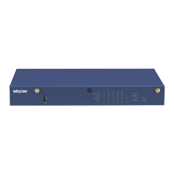
Page 17: Knowing Your Dna 1170
Used to plug a DC power cord. 6. DC In 2 (19V) Used to plug a DC power cord. 7. Power Button Press to power-on or power-off the system. Copyright © 2024 NEXCOM International Co., Ltd. All Rights Reserved. DNA 1170 Series User Manual... -
Page 18: Rear Panel
Used to connect to fiber optic networks, enabling long-distance networking or connections. 13. RJ45 LAN Ports Used to connect to local area networks (LANs) or other networking devices at 1GbE speed. Copyright © 2024 NEXCOM International Co., Ltd. All Rights Reserved. DNA 1170 Series User Manual... -
Page 19: Led Indicators
Behavior Description Inactive 9 11 12 Active/Traffic Active Flashing Green Data transferring Flashing Green 2.5GbE network link. Steady Green Link Steady Yellow 100Mbps network link. Copyright © 2024 NEXCOM International Co., Ltd. All Rights Reserved. DNA 1170 Series User Manual... - Page 20 Power on Steady Green Link PWR1 PWR2 PWR2 Steady red Power off 9 11 12 SSD LED Behavior Description Off (default) Flashing Green Data transferring Copyright © 2024 NEXCOM International Co., Ltd. All Rights Reserved. DNA 1170 Series User Manual...
-
Page 21: Chapter 2: Jumpers And Connectors
Static electricity can damage many of the electronic ▪ Use correct screws and do not over tighten screws. components. Humid environments tend to have less static electricity than Copyright © 2024 NEXCOM International Co., Ltd. All Rights Reserved. DNA 1170 Series User Manual... -
Page 22: Jumper Settings
(on) and open (off). Two-Pin Jumpers: Open (Left) and Short (Right) Three-Pin Jumpers: Pins 1 and 2 are Short Copyright © 2024 NEXCOM International Co., Ltd. All Rights Reserved. DNA 1170 Series User Manual... -
Page 23: Locations Of The Jumpers And Connectors
Locations of the Jumpers and Connectors The following figure shows the mainboard used in the DNA 1170 series, and indicate the locations of the jumpers and connectors. Refer to this chapter for detailed pin settings and definitions of the connectors marked in pink on this figure. -
Page 24: Jumpers
Connector location: JP14 Definition Definition U7_V20 RST_SRTCRST_N U7_U18 Function Function 1-2 On Normal (default) 1-2 On Normal (default) 2-3 On Clear RTC 2-3 On Clear CMOS Copyright © 2024 NEXCOM International Co., Ltd. All Rights Reserved. DNA 1170 Series User Manual... -
Page 25: Connector Pin Definitions
Chapter 2: Jumpers and Connectors Connector Pin Definitions External I/O Interfaces DC In Jack Power Button Connector location: CN2, CN3 Connector location: SW1 Definition Definition DC_IN PWRBTN#_IN Copyright © 2024 NEXCOM International Co., Ltd. All Rights Reserved. DNA 1170 Series User Manual... -
Page 26: Reset Button
Connector type: USB 3.0 port, Type A Connector location: USB1 Definition Definition 1,10 V5USB ACPI_BTN_IN# 2,11 USB2N0 3,12 USB2P0 5,14 USB3RN 6,15 USB3RP 8,17 USB3TN 9,18 USB3TP 4,13 USB_GND 7,16 Copyright © 2024 NEXCOM International Co., Ltd. All Rights Reserved. DNA 1170 Series User Manual... -
Page 27: Rj45 Console Port
Connector type: RJ45 Connector location: LAN1 Connector location: LAN1 Definition Definition SP_RTS1 1,3,7,9 LAN_MDIP SP_DTR1 2,4,8,10 LAN_MDIN0 SP_TXD1 LED2_ACT_N SP_DCD1 VCC3_LED SP_RXD1 LED1_L2500_N SP_DSR1 LED0_L1000_N SP_CTS1 Copyright © 2024 NEXCOM International Co., Ltd. All Rights Reserved. DNA 1170 Series User Manual... -
Page 28: Sfp+ Connectors
A11 A14 C11 C14 Definition Definition Definition VEET VEER SP_RTS1 TXFAULT SP_DTR1 TX_DISABLE SP_TXD1 VEER VCCR SP_DCD1 MOD-ABS VCCT SP_RXD1 VEET SP_DSR1 RX_LOS SP_CTS1 VEER VEET Copyright © 2024 NEXCOM International Co., Ltd. All Rights Reserved. DNA 1170 Series User Manual... -
Page 29: Usb 3.0 Port
Chapter 2: Jumpers and Connectors USB 3.0 Port Connector type: USB 3.0 port, Type A Connector location: CN8 Definition V5USB USB2N0 USB2P0 USB3RN USB3RP USB3TN USB3TP USB_GND Copyright © 2024 NEXCOM International Co., Ltd. All Rights Reserved. DNA 1170 Series User Manual... -
Page 30: Internal Connectors
Connector location: CN5 Definition Definition Definition P3V3_AUX SSD_DET_N P3V3_SSD P3V3_SSD CPLD_GPIN1 CPLD_GPOUT1 CPLD_GPIN2 M.2_ACT_LED1 CPLD_GPOUT2 P3V3_SSD CPLD_GPIN3 P3V3_SSD CPLD_GPOUT3 P3V3_SSD CPLD_GPIN4 P3V3_SSD CPLD_GPOUT4 Continued on next page Copyright © 2024 NEXCOM International Co., Ltd. All Rights Reserved. DNA 1170 Series User Manual... - Page 31 Mechanical Key Mechanical Key Mechanical Key NGFF_DEVSLP Mechanical Key Mechanical Key Mechanical Key Mechanical Key SATA2_RXP Mechanical Key CLK_32K_SUSCLK_SOC SATA2_RXN P3V3_SSD P3V3_SSD SATA2_TXN P3V3_SSD SATA2_TXP SSD_RST_N Copyright © 2024 NEXCOM International Co., Ltd. All Rights Reserved. DNA 1170 Series User Manual...
-
Page 32: Sata Connectors
Chapter 2: Jumpers and Connectors SATA Connectors FAN Connector Connector location: CN6, CN7 Connector location: CN10 Definition Definition Definition SATA_TXP SATA_TXN P12V_FAN SATA_RXN SATA_RXP FAN1_IN_CON FAN1_PWM_OUT Copyright © 2024 NEXCOM International Co., Ltd. All Rights Reserved. DNA 1170 Series User Manual... -
Page 33: Sata Power Connector
Chapter 2: Jumpers and Connectors SATA Power Connector CPLD JTAG Header Connector location: CON1, CON2 Connector location: JP1 Definition Definition P12V_AUX P3V3_AUX JTAG_PLD_TCK JTAG_PLD_TDO JTAG_PLD_TDI JTAG_PLD_TMS Copyright © 2024 NEXCOM International Co., Ltd. All Rights Reserved. DNA 1170 Series User Manual... -
Page 34: Tpm Connector
Chapter 2: Jumpers and Connectors TPM Connector CPLD Remote Update Connector Connector location: JP2 Connector location: JP3 Definition Definition 1,9,12,14 JTAG_SEL LPC_AD2 LPC_AD1 LPC_SERIRQ LPC_CLK_TPM LPC_FRAME_N RST_TPM_N LPC_AD3 LPC_AD0 Copyright © 2024 NEXCOM International Co., Ltd. All Rights Reserved. DNA 1170 Series User Manual... -
Page 35: Smb1 Uart Connector
Chapter 2: Jumpers and Connectors SMB1 UART Connector ME Recover Connector Connector location: JP4 Connector location: JP8 Definition Definition U7_V20 JTAG_SEL U7_U18 Copyright © 2024 NEXCOM International Co., Ltd. All Rights Reserved. DNA 1170 Series User Manual... -
Page 36: Mcu Pin
Chapter 2: Jumpers and Connectors MCU Pin Connector location: JP11 Definition MCU1_NMCLR MCU_Vdd MCU1_PGED MCU1_PGEC Copyright © 2024 NEXCOM International Co., Ltd. All Rights Reserved. DNA 1170 Series User Manual... -
Page 37: Block Diagram
Chapter 2: Jumpers and Connectors Block Diagram Copyright © 2024 NEXCOM International Co., Ltd. All Rights Reserved. DNA 1170 Series User Manual... -
Page 38: Removing The Chassis Cover
Remove these screws and put them in a safe place for later use. Note that the appearance of the chassis may vary, but the I/O ports and mechanics remain the same. Copyright © 2024 NEXCOM International Co., Ltd. All Rights Reserved. DNA 1170 Series User Manual... -
Page 39: Installing A So-Dimm Memory Module
Push the module down until the clips on both sides of the socket lock into position. The gold-plated connector on the edge of the module will almost completely disappear inside the socket. Copyright © 2024 NEXCOM International Co., Ltd. All Rights Reserved. DNA 1170 Series User Manual... -
Page 40: Installing A M.2 Storage Module
2. Insert the M.2 module into the M.2 slot at a 45-degree angle until the gold-plated connector on the edge of the module completely disappears into the slot. Secure the M.2 module using the screw. Copyright © 2024 NEXCOM International Co., Ltd. All Rights Reserved. DNA 1170 Series User Manual... -
Page 41: Chapter 4: Bios Setup
BIOS is updated in the future. second, to make settings appropriate for the way you use the computer. To check for the latest updates and revisions, visit the NEXCOM Web site at When to Configure the BIOS www.nexcom.com.tw. -
Page 42: Default Configuration
Powering on the computer and immediately pressing allows you to enter Setup. Load optimized default values. Saves and exits the Setup program. Press <Enter> to enter the highlighted sub-menu Copyright © 2024 NEXCOM International Co., Ltd. All Rights Reserved. DNA 1170 Series User Manual... - Page 43 When “” appears on the left of a particular field, it indicates that a submenu which contains additional options are available for that field. To display the submenu, move the highlight to that field and press Copyright © 2024 NEXCOM International Co., Ltd. All Rights Reserved. DNA 1170 Series User Manual...
-
Page 44: Bios Setup Utility
The Main menu is the first screen that you will see when you enter the BIOS hours from 00 to 23. Minute displays minutes from 00 to 59. Second displays Setup Utility. seconds from 00 to 59. Copyright © 2024 NEXCOM International Co., Ltd. All Rights Reserved. DNA 1170 Series User Manual... -
Page 45: Advanced
Enables or disables BIOS support for security device. O.S will not show Security Device. TCG EFI protocol and INT1A interface will not be available. Disable Block Sid Override to allow SID authentication in TCG storage device. Copyright © 2024 NEXCOM International Co., Ltd. All Rights Reserved. DNA 1170 Series User Manual... - Page 46 Display the Super I/O chip used on the board. Change Settings Serial Port 1 Configuration Select an optimal setting for the Super IO device. Configure the IO/IRQ settings of serial port 1. Copyright © 2024 NEXCOM International Co., Ltd. All Rights Reserved. DNA 1170 Series User Manual...
- Page 47 Control the NVRAM runtime variable protection through system admin password. Smart FAN enable Enable or disable the smart fan. Tolerrance Configure a tolerance for system fan target temperature. Copyright © 2024 NEXCOM International Co., Ltd. All Rights Reserved. DNA 1170 Series User Manual...
- Page 48 Select the serial port transmission speed. The speed must match the other side. Long or noisy lines may require a lower speed. Data Bits The options are 7 and 8. Copyright © 2024 NEXCOM International Co., Ltd. All Rights Reserved. DNA 1170 Series User Manual...
- Page 49 When this field is enabled, only text will be sent. This is to capture the terminal data. Resolution 100x31 Enable or disable extended terminal resolution. Putty Keypad Select the Putty keyboard emulation type. Copyright © 2024 NEXCOM International Co., Ltd. All Rights Reserved. DNA 1170 Series User Manual...
- Page 50 Enable or disable 64bit capable devices to be decoded in above 4G address space (only if the system supports 64 bit PCI decoding). SR-IOV Support Enable or disable SR-IOV support. Copyright © 2024 NEXCOM International Co., Ltd. All Rights Reserved. DNA 1170 Series User Manual...
- Page 51 This is a workaround for OSs that does not support XHCI hand-off. The XHCI ownership change should be claimed by the XHCI driver. USB Mass Storage Driver Support Enable or disable USB mass storage driver support. Copyright © 2024 NEXCOM International Co., Ltd. All Rights Reserved. DNA 1170 Series User Manual...
- Page 52 Auto option: Access SD device in DMA mode if controller supports it, otherwise in PIO mode. DMA option: Access SD device in DMA mode. PIO option: Access SD device in PIO mode. Copyright © 2024 NEXCOM International Co., Ltd. All Rights Reserved. DNA 1170 Series User Manual...
-
Page 53: Platform Configuration
Enter the SATA Configuration submenu. USB Configuration Enter the USB Configuration submenu. SCS Configuration Enter the SCS Configuration submenu. State After G3 Configure the PCH state after G3. Copyright © 2024 NEXCOM International Co., Ltd. All Rights Reserved. DNA 1170 Series User Manual... - Page 54 Enable or disable the ASPM. L1 Substates Configure the L1 Substates settings. PCIe Speed Configure the speed of the PCI Express port. Configure the CT0 for PCI Express. Copyright © 2024 NEXCOM International Co., Ltd. All Rights Reserved. DNA 1170 Series User Manual...
- Page 55 Enable or disable software feature mask configuration for controller 1. Aggressive LPM Support Enable or disable aggressive LPM support. Port 6 Enable or disable SATA port 6. Copyright © 2024 NEXCOM International Co., Ltd. All Rights Reserved. DNA 1170 Series User Manual...
- Page 56 USB Port Disable Override Enable or disable DITO configuration. Selectively enable or disable the corresponding USB port from reporting a device connection to the controller. Copyright © 2024 NEXCOM International Co., Ltd. All Rights Reserved. DNA 1170 Series User Manual...
- Page 57 Display information of the firmware installed in the system. eMMC 5.1 Controller Enable or disable SCS eMMC 5.1 controller. eMMC 5.1 HS400 Mode Enable or disable SCS eMMC 5.1 HS400 mode. Copyright © 2024 NEXCOM International Co., Ltd. All Rights Reserved. DNA 1170 Series User Manual...
-
Page 58: Socket Configuration
Memory Configuration Enter the Memory Configuration submenu. IIO Configuration Enter the IIO Configuration submenu. Advanced Power Management Configuration Enter the Advanced Power Management Configuration submenu. Copyright © 2024 NEXCOM International Co., Ltd. All Rights Reserved. DNA 1170 Series User Manual... - Page 59 Chapter 4: BIOS Setup Pre-Socket Configuration Memory Configuration Pre-Socket Configuration Memory Topology Change pre-socket settings. Display memory topology with DIMM population information. Copyright © 2024 NEXCOM International Co., Ltd. All Rights Reserved. DNA 1170 Series User Manual...
- Page 60 Select PCIe port bifurcation for selected slot(s). Enter the Socket0 Configuration submenu. Intel VT for Directed I/O (VT-d) Enter the Intel VT for Directed I/O (VT-d) submenu. Copyright © 2024 NEXCOM International Co., Ltd. All Rights Reserved. DNA 1170 Series User Manual...
- Page 61 Enable or disable the DMA Control Opt-In Flag. Interrupt Remapping Configure the Interrupt Remapping. X2APIC Opt-Out Enable or disable the X2APIC mode. Pre-boot DMA Protection Enable or disable the Pre-boot DMA Protection Copyright © 2024 NEXCOM International Co., Ltd. All Rights Reserved. DNA 1170 Series User Manual...
- Page 62 Enable or disable Enhanced Halt State (C1E) for lower power consumption. OS ACPI Cx Enable or disable C3 report or C6 report to OS ACPI C2 or ACPI C3. Copyright © 2024 NEXCOM International Co., Ltd. All Rights Reserved. DNA 1170 Series User Manual...
-
Page 63: Security
Chapter 4: BIOS Setup Security Administrator Password Select to reconfigure the administrator’s password. Copyright © 2024 NEXCOM International Co., Ltd. All Rights Reserved. DNA 1170 Series User Manual... -
Page 64: Boot
When set to Off, the function of the numeric keypad is the arrow keys. Quiet Boot Enabled Display OEM logo instead of the POST messages. Disabled Display normal POST messages. Fast Copyright © 2024 NEXCOM International Co., Ltd. All Rights Reserved. DNA 1170 Series User Manual... -
Page 65: Save & Exit
Confirm by selecting Yes. Launch EFI Shell from filesystem device To launch EFI shell from a filesystem device, select this field and press <Enter>. Copyright © 2024 NEXCOM International Co., Ltd. All Rights Reserved. DNA 1170 Series User Manual...
Need help?
Do you have a question about the DNA 1170 Series and is the answer not in the manual?
Questions and answers