
Related Manuals for Nexcom Neu-X304 Series


Summary of Contents for Nexcom Neu-X304 Series
- Page 1 NEXCOM International Co., Ltd. Intelligent Platform & Services Business Unit Edge Computing System Neu-X304 Series User Manual NEXCOM International Co., Ltd. www.nexcom.com Published April 2024...
-
Page 2: Table Of Contents
Declaration of Conformity ..............iv Precautions ....................6 RoHS Compliance ................... v Jumper Settings ..................7 Warranty and RMA ................vi Locations of the Jumpers and Connectors for the Neu-X304 Series ..8 Safety Information ................viii Jumpers & DIP Switches ................10 Installation Recommendations ...............viii Clear CMOS ..................10 Safety Precautions .................. - Page 3 Installing a 5G/LTE Module (M.2 Key B) ..........34 Installing a CPU ..................36 Wall Mounting Instructions ..............39 Chapter 4: BIOS Setup About BIOS Setup .................38 When to Configure the BIOS ..............38 Copyright © 2024 NEXCOM International Co., Ltd. All Rights Reserved. Neu-X304 Series User Manual...
-
Page 4: Preface
No describes how to keep the system CE compliant. part of this manual may be reproduced, copied, translated or transmitted in any form or by any means without the prior written consent from NEXCOM Declaration of Conformity International Co., Ltd. -
Page 5: Rohs Compliance
(Cr6+) < 0.1% or 1,000ppm, Polybrominated biphenyls (PBB) < 0.1% or 1,000ppm, and Polybrominated diphenyl Ethers (PBDE) < 0.1% or 1,000ppm. In order to meet the RoHS compliant directives, NEXCOM has established an engineering and manufacturing task force to implement the introduction of green products. -
Page 6: Warranty And Rma
“NEXCOM RMA Service Form” for the RMA number apply process. ▪ If RMA goods can not be repaired, NEXCOM will return it to the customer without any charge. ▪ Customers can send back the faulty products with or without accessories (manuals, cable, etc.) and any components from the card, such as CPU... - Page 7 ESD workstation. If no such station is available, you can provide some ESD protection by wearing an antistatic wrist strap and attaching it to a metal part of the computer chassis. Copyright © 2024 NEXCOM International Co., Ltd. All Rights Reserved. Neu-X304 Series User Manual...
-
Page 8: Safety Information
There is a danger of explosion if battery is incorrectly replaced. Replace only with the same or equivalent type recommended by the manufacturer. Discard used batteries according to the manufacturer’s instructions. viii Copyright © 2024 NEXCOM International Co., Ltd. All Rights Reserved. Neu-X304 Series User Manual... -
Page 9: Safety Precautions
UL/IEC 60950-1 and/or UL/IEC 62368-1. If further assistance is needed, please contact NEXCOM International Co., Ltd. (UL file owner or brand owner) for further information. Copyright © 2024 NEXCOM International Co., Ltd. All Rights Reserved. -
Page 10: Technical Support And Assistance
Preface Technical Support and Assistance Conventions Used in this Manual 1. For the most updated information of NEXCOM products, visit NEXCOM’s Warning: website at www.nexcom.com. Information about certain situations, which if not observed, can cause personal injury. This will prevent injury to yourself 2. -
Page 11: Global Service Contact Information
Tel: +886-2-8226-7786 Tel: +886-2-8976-3077 Beitun District, Fax: +886-2-8226-7782 Email: sales@diviotec.com Taichung City, 406, Taiwan, R.O.C. Email: services@tmrtek.com www.diviotec.com Tel: +886-4-2249-1179 www.tmrtek.com Fax: +886-4-2249-1172 Email: jacobhuang@nexaiot.com www.nexaiot.com Copyright © 2024 NEXCOM International Co., Ltd. All Rights Reserved. Neu-X304 Series User Manual... - Page 12 9F, Tamachi Hara Bldg., LongGang District, 4-11-5, Shiba Minato-ku, ShenZhen, 518112, China Tokyo, 108-0014, Japan Tel: +86-755-8364-7768 Tel: +81-3-5419-7830 Fax: +86-755-8364-7738 Fax: +81-3-5419-7832 Email: steveyang@nexcom.com.tw Email: sales@nexcom-jp.com www.nexcom.cn www.nexcom-jp.com Copyright © 2024 NEXCOM International Co., Ltd. All Rights Reserved. Neu-X304 Series User Manual...
-
Page 13: Package Contents
35x30x1.5mm PK404HC 5060200500X00 Thermal Pad for Wi-Fi module 18x18x1.5mm K=2.5 W/mk PK404HC 7400120034X00 Power Adapter POWER ADAPTER EDAC:EA11011H(T25) 120W 12V/10A W/LOCK 4 PIN DC JACK xiii Copyright © 2024 NEXCOM International Co., Ltd. All Rights Reserved. Neu-X304 Series User Manual... -
Page 14: Ordering Information
PCH Q670E, 3x HDMI, 12-24V DC ® ® Neu-X304-H (P/N:10W10X30401X0) 12th/13th Intel ® Core ™ Edge Computing fanless system w/ Intel ® PCH H610E, 3x HDM, 12V DC only Copyright © 2024 NEXCOM International Co., Ltd. All Rights Reserved. Neu-X304 Series User Manual... -
Page 15: Chapter 1: Product Introduction
Front Panel ▪ Support Intel AMT Technology (Q670E support) ® ▪ TPM 2.0 IC onboard ▪ Support 12V/12-24V DC Power Input ▪ Fanless Design Rear Panel Copyright © 2024 NEXCOM International Co., Ltd. All Rights Reserved. Neu-X304 Series User Manual... -
Page 16: Hardware Specifications
▪ 1 x HDD LED Indicator IEC60068-2-2, IEC60068-2-14) ▪ 2 x COM ports: ▪ Relative humidity (non-condensing): 95% (non-condensing) – COM1: RS232/422/485 – COM2: RS232, support RI/12V/5V, select by jumper Copyright © 2024 NEXCOM International Co., Ltd. All Rights Reserved. Neu-X304 Series User Manual... - Page 17 ▪ Aluminum and metal chassis with fanless design ▪ 240mm(L) x 210(W) x 54mm (H) with mounting bracket ▪ 210mm(L) x 210(W) x 50mm (H) w/o mounting bracket Operating System ▪ Win10/Win11/Linux Copyright © 2024 NEXCOM International Co., Ltd. All Rights Reserved. Neu-X304 Series User Manual...
-
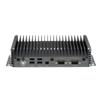
Page 18: Physical Features
Antenna Holes Antenna Holes Storage LED Remote Switch COM2 12-24V DC-In LAN1 HDMI 2.0 Line-Out i219-LM Power Button USB 2.0 COM1 USB 3.2 LAN2 Mic-In i226-V Copyright © 2024 NEXCOM International Co., Ltd. All Rights Reserved. Neu-X304 Series User Manual... -
Page 19: Physical Features
Antenna Holes Storage LED Remote Switch COM2 12V DC-In USB 2.0 LAN2 Mic-In i226-V Power Button USB 2.0 COM1 USB 3.2 LAN1 HDMI 2.0 Line-Out i219-LM Copyright © 2024 NEXCOM International Co., Ltd. All Rights Reserved. Neu-X304 Series User Manual... -
Page 20: Mechanical Dimensions
Chapter 1: Product Introduction Mechanical Dimensions #6-32 NUT Copyright © 2024 NEXCOM International Co., Ltd. All Rights Reserved. Neu-X304 Series User Manual... -
Page 21: Chapter 2: Jumpers And Connectors
Static electricity can damage many of the electronic ▪ Use correct screws and do not over tighten screws. components. Humid environments tend to have less static electricity than Copyright © 2024 NEXCOM International Co., Ltd. All Rights Reserved. Neu-X304 Series User Manual... -
Page 22: Jumper Settings
(on) and open (off). Two-Pin Jumpers: Open (Left) and Short (Right) Three-Pin Jumpers: Pins 1 and 2 are Short Copyright © 2024 NEXCOM International Co., Ltd. All Rights Reserved. Neu-X304 Series User Manual... -
Page 23: Locations Of The Jumpers And Connectors For The Neu-X304 Series
Locations of the Jumpers and Connectors for the Neu-X304 Series The following figures show the motherboard of Neu-X304 series, and indicates the locations of jumpers and connectors. Refer to this chapter for detailed pin setting and definitions of connectors marked in pink on this figure. - Page 24 Chapter 2: Jumpers and Connectors Copyright © 2024 NEXCOM International Co., Ltd. All Rights Reserved. Neu-X304 Series User Manual...
-
Page 25: Jumpers & Dip Switches
Connector type: 1x5-pin header, 2.0mm pitch Connector location: CLRCMOS Connector location: JP1 Settings Settings 1-2 On Normal (default) RI (Default) 2-3 On Clear CMOS COM2_RI (Default) COM2_RI +12V Copyright © 2024 NEXCOM International Co., Ltd. All Rights Reserved. Neu-X304 Series User Manual... -
Page 26: Lcd Panel Voltage Select
1680 x 1050 8-bit Dual Port 1101 1600 x 1200 8-bit Dual Port 1110 1920 x 1080 8-bit Dual Port 1111 1920 x 1200 8-bit Dual Port Copyright © 2024 NEXCOM International Co., Ltd. All Rights Reserved. Neu-X304 Series User Manual... -
Page 27: Connector Pin Definitions
Connector type: Phone Jack single port, 6P, green Connector location: CN1 Connector location: CN2 Definition Definition Definition Definition MIC_R MIC_JD LOUT_R LOUT_JD AGND LOUT_L AGND LOUT_L AGND AGND AGND AGND Copyright © 2024 NEXCOM International Co., Ltd. All Rights Reserved. Neu-X304 Series User Manual... -
Page 28: Hdmi Port
CGND HDMI_P5V LED Indicators HDMI_HPD Status Link Status Flashing Yellow Data activity Steady Green 1G network link No activity Steady Orange 100Mbps network link No activity Copyright © 2024 NEXCOM International Co., Ltd. All Rights Reserved. Neu-X304 Series User Manual... -
Page 29: Lan Port (I226-V)
CGND CGND Flashing Yellow Data activity Steady Green 1G/2.5G network link 100Mbps network link No activity Steady Orange or 10Mbps no activity 10Mbps or no link Copyright © 2024 NEXCOM International Co., Ltd. All Rights Reserved. Neu-X304 Series User Manual... -
Page 30: Usb Ports (Neu-X304-H)
Definition Definition USB2_3N +12VSUS +12VSUS USB2_3P USB3_RX3N USB3_RX3P CGND USB3_TX3N USB3_TX3P USB2_4N USB2_4P USB3_RX4N USB3_RX4P USB3_TX4N USB3_TX4P CGND CGND CGND CGND USB2.0 Definition Definition USB2_N USB2_P Copyright © 2024 NEXCOM International Co., Ltd. All Rights Reserved. Neu-X304 Series User Manual... -
Page 31: Internal I/O Interfaces
Connector type: WtoB, 1x2-pin header, 1.25mm Connector type: WtoB, 1x9-pin header, 1.0mm pitch Connector location: BAT1 Connector location: COM1, COM2 COM3, and COM4 Definition Definition Definition CTS# RTS# DSR# DTR# DCD# Copyright © 2024 NEXCOM International Co., Ltd. All Rights Reserved. Neu-X304 Series User Manual... -
Page 32: Atx +12V Power Connector
Connector type: WtoB, 1x4-pin header, 2.54mm pitch Connector location: CON1 Connector location: CPU_FAN Definition Definition Definition Definition +12V +12VSUS +12VSUS CPU FAN SPEED DETECT CPU FAN SPEED CONTROL Copyright © 2024 NEXCOM International Co., Ltd. All Rights Reserved. Neu-X304 Series User Manual... -
Page 33: Debug Port/Lpc Bus Connector
Connector location: DEBUG Connector location: GPIO Definition Definition Definition Definition PLTRST# ESPI_CLK ESPI_CS# GPO0 GPO1 ESPI_IO3 ESPI_IO2 GPO2 GPO3 ESPI_IO1 ESPI_IO0 GPI0 GPI1 ESPI_RST# 3.3V GPI2 GPI3 Copyright © 2024 NEXCOM International Co., Ltd. All Rights Reserved. Neu-X304 Series User Manual... -
Page 34: Lvds Inverter Connector
Chapter 2: Jumpers and Connectors LVDS Inverter Connector Connector type: 2x3, 6-pin header JST, 2.54mm pitch Connector location: INVN1 Definition Definition +V_INV +V_INV INV_BKLTEN INV_BKLTCTRL Copyright © 2024 NEXCOM International Co., Ltd. All Rights Reserved. Neu-X304 Series User Manual... -
Page 35: Lvds/Edp Panel Connector
LVDS_DAT2N LVDS_DAT5N LVDS_CLK2P LVDS_DAT1P LVDS_DAT4P LVDS_CLK2N LVDS_DAT1N LVDS_DAT4N LVDS_CLK1P +V_INV LVDS_DAT0P LVDS_CLK1N +V_INV LVDS_DAT0N +V_PANEL +V_INV LVDS_DAT7P +V_PANEL +V_INV LVDS_DAT7N +V_PANEL N.C. Continued on next page Copyright © 2024 NEXCOM International Co., Ltd. All Rights Reserved. Neu-X304 Series User Manual... - Page 36 +V_PANEL INV_BKLTEN EDP_TX0P N.C. INV_BKLTCTRL EDP_TX0N N.C. N.C. EDP_TX1P N.C. N.C. EDP_TX1N N.C. EDP_AUXP +V_INV EDP_HPD EDP_AUXN +V_INV N.C. +V_PANEL +V_INV N.C. +V_PANEL +V_INV N.C. +V_PANEL Copyright © 2024 NEXCOM International Co., Ltd. All Rights Reserved. Neu-X304 Series User Manual...
-
Page 37: M.2 Key B 3042/3052 Connector
3.3V 3.3V WWAN_GPS_ON POWER_OFF# USB2_5P WIFI_DIS# USB3_RXN UIM_RESET USB2_5N LED# USB3_RXP UIM_CLK UIM_DATA USB3_TXN UIM_PWR USB3_TXP Telit FN980 PCIe/USB Select Pin CONFIG0 Continued on next page Copyright © 2024 NEXCOM International Co., Ltd. All Rights Reserved. Neu-X304 Series User Manual... - Page 38 Chapter 2: Jumpers and Connectors Definition Definition Definition Definition PCIE_RXN PCIE_RXP PCIE_TXN PCIE_TXP RESET(3.3V) RESET(1.8V) SUS_CLK CLKREQ# CONFIG1 3.3V CLK_DN WAKE# 3.3V CLK_DP 3.3V CONFIG2 Copyright © 2024 NEXCOM International Co., Ltd. All Rights Reserved. Neu-X304 Series User Manual...
-
Page 39: M.2 Key E 2230 Connector
SDIO_RESET# GND2 PCM_CLK SDIO_CLK PCM_SYNC UART_TXD SDIO_CMD PCM_IN GND4 UART_CTS SDIO_DATA0 PCM_OUT PETP0 UART_RTS SDIO_DATA1 LED2# PETN0 RESERVED_1 SDIO_DATA2 GND3 GND5 RESERVED_2 Continued on next page Copyright © 2024 NEXCOM International Co., Ltd. All Rights Reserved. Neu-X304 Series User Manual... - Page 40 COEX2 GND9 RESERVED REFCLKP0 COEX1 PERP1 UIM_SWP REFCLKN0 SUSCLK PERN1 UIM_POWER_SNK GND7 PERST0# GND10 UIM_POWER_SRC CLKREQ0# W_DISABLE2# PEFCLKP1 3.3V_3 PEWAKE0# W_DISABLE1# PEFCLKN1 3.3V_4 GND8 I2C_DATA GND11 Copyright © 2024 NEXCOM International Co., Ltd. All Rights Reserved. Neu-X304 Series User Manual...
-
Page 41: M.2 Key M 2280 Connector
Definition Definition Definition Definition VCC3 PCIE2_RXP VCC3 PCIE3_RXN PCIE2_TXN PCIE3_RXP PCIE2_TXP M2M_LED# PCIE3_TXN VCC3 PCIE1_RXN PCIE3_TXP VCC3 PCIE1_RXP VCC3 PCIE2_RXN VCC3 PCIE1_TXN Continued on next page Copyright © 2024 NEXCOM International Co., Ltd. All Rights Reserved. Neu-X304 Series User Manual... - Page 42 Chapter 2: Jumpers and Connectors Definition Definition Definition Definition PCIE1_TXP DEVSLP CLK_PCIEP CLKREQ# WAKE# SATA_RXP(PCIE0_RXP) DEVSLP SATA_RXN(PCIE0_RXN) M2M_PEDET VCC3 SATA_TXN(PCIE0_TXN) VCC3 SATA_TXP(PCIE0_TXP) VCC3 CLK_PCIEN RESET# Copyright © 2024 NEXCOM International Co., Ltd. All Rights Reserved. Neu-X304 Series User Manual...
-
Page 43: System Power Button Connector
Connector type: WtoB,1x2-pin header, 1.0mm pitch Connector type: 1x6-pin header, 2.0mm pitch Connector location: PWR_BTN Connector location: RESET_LED Definition Definition PWRBTN# RESET# HDD_LED+ HDD_LED- PWR_LED+ PWR_LED- Copyright © 2024 NEXCOM International Co., Ltd. All Rights Reserved. Neu-X304 Series User Manual... -
Page 44: System Power Button Connector
Connector type: Standard Serial ATA 7P (1.27mm, SATA-M-180) Connector type: 1x2 2-pin header, 2.5mm pitch Connector location: SATA1 Connector location: SATA_PWR1 Definition Definition SATA_TXP SATA_TXN SATA_RXN SATA_RXP Copyright © 2024 NEXCOM International Co., Ltd. All Rights Reserved. Neu-X304 Series User Manual... -
Page 45: Speaker Connector
Connector type: WtoB, 1x4-pin header, 1.25mm pitch Connector location: SPK Connector location: SYS_FAN Definition Definition Definition L_OUT+ +12V L_OUT- SYS FAN SPEED DETECT SYS FAN SPEED CONTROL R_OUT+ R_OUT- Copyright © 2024 NEXCOM International Co., Ltd. All Rights Reserved. Neu-X304 Series User Manual... -
Page 46: Internal Usb 2.0 Connector
Chapter 2: Jumpers and Connectors Internal USB 2.0 Connector Connector type: WtoB,1x6-pin header, 1.0mm pitch Connector location: USB2_56P, USB2_914P Definition USB2N USB2P USB1N USB1P Copyright © 2024 NEXCOM International Co., Ltd. All Rights Reserved. Neu-X304 Series User Manual... -
Page 47: Chapter 3: System Setup
The screws on the front, rear, and bottom are used to secure the cover to the chassis. Remove these screws and put them in a safe place for later use. Copyright © 2024 NEXCOM International Co., Ltd. All Rights Reserved. Neu-X304 Series User Manual... -
Page 48: Installing An M.2 Ssd Module (M-Key 2280)
Loosen the screws from the bottom cover and then remove the cover. Remove the screw from the standoff and put it in a safe place for later use. M.2 Slot for SSD Copyright © 2024 NEXCOM International Co., Ltd. All Rights Reserved. Neu-X304 Series User Manual... - Page 49 With the module fully inserted, tighten the screw removed earlier into the mounting hole on the module to secure it. Copyright © 2024 NEXCOM International Co., Ltd. All Rights Reserved. Neu-X304 Series User Manual...
-
Page 50: Installing A So-Dimm Memory Module
Push the module down until the clips on both sides of the socket lock into position. The gold-plated connector on the edge of the module will almost completely disappear inside the socket. Memory Socket Copyright © 2024 NEXCOM International Co., Ltd. All Rights Reserved. Neu-X304 Series User Manual... -
Page 51: Installing A Wi-Fi Module (M.2 Key E)
Push the module down cable through the antenna hole. and tighten a screw into the mounting hole on the module to secure it. Antenna hole Copyright © 2024 NEXCOM International Co., Ltd. All Rights Reserved. Neu-X304 Series User Manual... - Page 52 Insert the 2 rings (ring 1 then ring 2) into the Wi-Fi antenna jacks. Connect the external antenna to the Wi-Fi antenna jack. Ring 1 Ring 2 Copyright © 2024 NEXCOM International Co., Ltd. All Rights Reserved. Neu-X304 Series User Manual...
-
Page 53: Installing A 5G/Lte Module (M.2 Key B)
Push the module down cable through the antenna hole. and tighten a screw into the mounting hole on the module to secure it. Copyright © 2024 NEXCOM International Co., Ltd. All Rights Reserved. Neu-X304 Series User Manual... - Page 54 Insert the rings (ring 1 then ring 2) into the 5G or LTE antenna jacks. Connect the external antenna to the 5G or LTE antenna jack. Ring 1 Ring 2 Copyright © 2024 NEXCOM International Co., Ltd. All Rights Reserved. Neu-X304 Series User Manual...
-
Page 55: Installing A Cpu
Unlock the socket by pushing the load lever down, moving it sideways socket. until it is released from the retention tab; then lift the load lever up. Retention Tab Load Lever Copyright © 2024 NEXCOM International Co., Ltd. All Rights Reserved. Neu-X304 Series User Manual... - Page 56 ▪ The CPU will fit in only one orientation and can easily be CAUTION! CAUTION! CAUTION! CAUTION! the socket may bend the pins and damage the CPU. inserted without exerting any force. Copyright © 2024 NEXCOM International Co., Ltd. All Rights Reserved. Neu-X304 Series User Manual...
- Page 57 Chapter 3: System Setup Use the thermal grease to dispense on CPU surface such as below. Reinstall the heat sink with the four mounting screws removed earlier. Copyright © 2024 NEXCOM International Co., Ltd. All Rights Reserved. Neu-X304 Series User Manual...
-
Page 58: Wall Mounting Instructions
Wall Mount Bracket Specification of the wall mount screw: Round Head Screw Long Fei: P6#32TX8L_w/Spring+Flat Washer Fasten screws to mount the system to the wall Copyright © 2024 NEXCOM International Co., Ltd. All Rights Reserved. Neu-X304 Series User Manual... -
Page 59: Chapter 4: Bios Setup
BIOS is updated in the future. second, to make settings appropriate for the way you use the computer. To check for the latest updates and revisions, visit the NEXCOM website at When to Configure the BIOS www.nexcom.com.tw. -
Page 60: Default Configuration
Powering on the computer and immediately pressing <Del> allows you to enter Setup. Load optimized default values. Press the key to enter Setup: Saves and exits the Setup program. Press <Enter> to enter the highlighted sub-menu Copyright © 2024 NEXCOM International Co., Ltd. All Rights Reserved. Neu-X304 Series User Manual... - Page 61 When “” appears on the left of a particular field, it indicates that a submenu which contains additional options are available for that field. To display the submenu, move the highlight to that field and press Copyright © 2024 NEXCOM International Co., Ltd. All Rights Reserved. Neu-X304 Series User Manual...
-
Page 62: Bios Setup Utility
The Main menu is the first screen that you will see when you enter the BIOS hours from 00 to 23. Minute displays minutes from 00 to 59. Second Setup Utility. displays seconds from 00 to 59. Copyright © 2024 NEXCOM International Co., Ltd. All Rights Reserved. Neu-X304 Series User Manual... -
Page 63: Advanced
Specify what state to go to when power is re-applied after a power failure tion. (G3 State). Wake on LAN/COM Enable or disable integrated LAN/COM port RI to wake the system. Copyright © 2024 NEXCOM International Co., Ltd. All Rights Reserved. Neu-X304 Series User Manual... - Page 64 When this field is set to Enabled, the VMM can utilize the additional hardware capabilities provided by Vanderpool Technology. Inte(R) SpeedStep(tm) Allow more than two frequency ranges to be supported. Copyright © 2024 NEXCOM International Co., Ltd. All Rights Reserved. Neu-X304 Series User Manual...
- Page 65 CPPC v2 interface to allow hardware controlled P-states. Turbo Mode Enable or disable processor turbo mode (requires EMTTM enabled too). Auto means enabled. SATA Test Mode Enable or disable test mode (loop back). Copyright © 2024 NEXCOM International Co., Ltd. All Rights Reserved. Neu-X304 Series User Manual...
- Page 66 Enable or disable SHA256 PCR Bank. Pending operation Schedule an operation for the security device. Note: Your computer will reboot during restart in order to change state of security device. Copyright © 2024 NEXCOM International Co., Ltd. All Rights Reserved. Neu-X304 Series User Manual...
- Page 67 Press <Enter> to set parameters of serial port 2 (COMB). Select the highest ACPI sleep state the system will enter when the suspend button is pressed. Copyright © 2024 NEXCOM International Co., Ltd. All Rights Reserved. Neu-X304 Series User Manual...
- Page 68 Select a mode for serial port 1. When select RS422/485 mode, the feature of terminal resistor will be available for configuration. Terminal Resistor Enable or disable built-in termination resistor and bias resistor. TX enable low active. Copyright © 2024 NEXCOM International Co., Ltd. All Rights Reserved. Neu-X304 Series User Manual...
- Page 69 Smart Fan Function SYSFAN Setting Smart Fan Function Enter the SYSFAN Setting submenu. Enter the Smart Fan Function submenu. CPUFAN Setting Enter the CPUFAN Setting submenu. Copyright © 2024 NEXCOM International Co., Ltd. All Rights Reserved. Neu-X304 Series User Manual...
- Page 70 Manual PWM Manual PWM Fan will work with this manual PWM value (0~255 for 0%~100%). Fan will work with this manual PWM value (0~255 for 0%~100%). Copyright © 2024 NEXCOM International Co., Ltd. All Rights Reserved. Neu-X304 Series User Manual...
- Page 71 Enable or disable IPv4 PXE support. If disabled, the IPv4 boot option will not be created. Ipv4 HTTP Support Enable or disable IPv4 HTTP support. If disabled, the IPv4 boot option will not be created. Copyright © 2024 NEXCOM International Co., Ltd. All Rights Reserved. Neu-X304 Series User Manual...
- Page 72 This section is used to configure the NVMe devices. The options will become This section is used to display information of the Intel Ethernet controller. available once the system detects an installed NVMe device. Copyright © 2024 NEXCOM International Co., Ltd. All Rights Reserved. Neu-X304 Series User Manual...
-
Page 73: Security
Chapter 4: BIOS Setup Security Administrator Password Select to reconfigure the administrator’s password. Copyright © 2024 NEXCOM International Co., Ltd. All Rights Reserved. Neu-X304 Series User Manual... -
Page 74: Boot
Adjust the boot sequence of the system. Boot Option #1 is the first boot device that the system will boot from, next will be #2 and so forth. Copyright © 2024 NEXCOM International Co., Ltd. All Rights Reserved. Neu-X304 Series User Manual... -
Page 75: Save & Exit
To exit the Setup utility without saving the changes, select this field then press <Enter>. You may be prompted to confirm again before exiting. You can also press <ESC> to exit without saving the changes. Copyright © 2024 NEXCOM International Co., Ltd. All Rights Reserved. Neu-X304 Series User Manual... -
Page 76: Mebx
Chapter 4: BIOS Setup MEBx This MEBx menu is allowed you to view and changed the MEBx congfuration. INTEL(R) ME Password MEBx Login and configure AMT BIOS features. Copyright © 2024 NEXCOM International Co., Ltd. All Rights Reserved. Neu-X304 Series User Manual... -
Page 77: Appendix A: Power Consumption
Full-Loading Test program: Win 10 x64 with BurnIn Test V10.2 (1007) 2D Graphic Network 3D Graphic Serial Port Sound Disk(M.2) Video Playback GPGPU USB Port x6 (Connect load Device) Memory(RAM) Copyright © 2024 NEXCOM International Co., Ltd. All Rights Reserved. Neu-X304 Series User Manual... -
Page 78: Appendix B: Gpi/O Programming Guide
(PCB A) GPI/O (General Purpose Input/Output) pins are provided for custom system design. This appendix provides definitions and its default setting for the ten GPI/O pins in the Neu-X304 series. The pin definition is shown in the following table: Pin No. - Page 79 #define GPO1_LO outportb(0xA02, 0x00) #define GPO2_HI outportb(0xA02, GPO2) #define GPO2_LO outportb(0xA02, 0x00) #define GPO3_HI outportb(0xA02, GPO3) #define GPO3_LO outportb(0xA02, 0x00) void main(void) GPO3X; GPO0_HI; GPO1_LO; GPO2_HI; GPO3_LO; Copyright © 2024 NEXCOM International Co., Ltd. All Rights Reserved. Neu-X304 Series User Manual...
-
Page 80: Appendix C: Watchdog Timer Setting
WDT_SET); outportb(SUPERIO_PORT+1, 0x00); # Use the second # Use the minute, change value to 0x08 # Set WDT sec/min outportb(SUPERIO_PORT, WDT_VALUE); outportb(SUPERIO_PORT+1, 0x05); #Set 5 seconds Copyright © 2024 NEXCOM International Co., Ltd. All Rights Reserved. Neu-X304 Series User Manual...
Need help?
Do you have a question about the Neu-X304 Series and is the answer not in the manual?
Questions and answers