Table of Contents
Advertisement
Quick Links
Advertisement
Table of Contents

Subscribe to Our Youtube Channel
Related Manuals for Ford PRO NB 120 Series


Summary of Contents for Ford PRO NB 120 Series
- Page 1 Ford Pro DC Charging Station NB 120 series Installation Manual...
- Page 2 NB 120 series Installation Manual Edition: June 2023 NB120HW02AI Rev. A...
-
Page 3: About This Manual
The manufacturer reserves the right to modify product features. TARGET AUDIENCE This manual is intended for qualified personnel who will install, configure, and operate the chargers. Only qualified technical personnel validated by the manufacturer may install and start up the equipment. Ford Pro contact info: chargingsupport@fordpro.com and 1-800-34-FLEET... - Page 4 The equipment and technical documentation are periodically updated. The manufacturer reserves the right to modify all or part of the contents of this manual without previous notice. The reproduction or distribution of the present manual is strictly forbidden unless express authorization from the manufacturer. Ford Pro contact info: chargingsupport@fordpro.com and 1-800-34-FLEET...
-
Page 5: Table Of Contents
6. CABLE ACCESS AND CONNECTIONS ....................31 Access ..............................32 Connections ............................35 7. PROTECTIONS ............................40 Insulation monitoring ........................... 40 Overcurrent and short circuit protection ....................40 8. INTERFACE ............................41 Controls .............................. 41 LED indicators ............................ 41 Ford Pro contact info: chargingsupport@fordpro.com and 1-800-34-FLEET... - Page 6 11. COMMISSIONING ..........................51 12. SAFE STOP ............................52 13. EMERGENCY STOP AND RESTART ....................53 14. MAINTENANCE ............................ 54 Equipment statuses ..........................54 Checklist ............................. 55 Status 1 .............................. 56 Status 2 .............................. 57 Ford Pro contact info: chargingsupport@fordpro.com and 1-800-34-FLEET...
-
Page 7: Acronyms
Multi Power Conversion System Measuring Instrument Directive Medium Voltage. This term is used to refer to high voltage in general Ground connection Proportional and Integral Point Of Interconnection Personal Protection Equipment Photovoltaic energy Residual Current Device Ford Pro contact info: chargingsupport@fordpro.com and 1-800-34-FLEET... - Page 8 Grid system where both the power supply and the electrical devices are connected to the ground via separate connections Uninterruptible Power Supply VSD / VFD Variable Speed Drive, Variable Frequency Drive. Both terms are used Ford Pro contact info: chargingsupport@fordpro.com and 1-800-34-FLEET...
-
Page 9: Safety Symbols
Risk of fire. Be careful and follow the instructions to prevent causing an unintentional fire. Caution, risk of electric shock. Energy storage timed discharge. Wait for the indicated time to avoid electrical hazards. Ford Pro contact info: chargingsupport@fordpro.com and 1-800-34-FLEET... -
Page 10: Important Safety Instructions
4. Ground and short-circuit all possible voltage sources. 5. Mark the working area and keep out zone. Do not modify the equipment. If you do so, Power Electronics will not assume any liability, and the product warranty will be voided. Ford Pro contact info: chargingsupport@fordpro.com and 1-800-34-FLEET... - Page 11 Only connect the grounding device to the equipment's grounding plate. Do not use the enclosure or chassis screws for grounding. • The protective ground cable must be first to connect and last to disconnect. Ford Pro contact info: chargingsupport@fordpro.com and 1-800-34-FLEET...
- Page 12 Follow the directions given by the vehicle manufacturer regarding the suitability of charging the vehicle when you or the vehicle are exposed to intense rain, heavy electrical storm, or other severe weather. Ford Pro contact info: chargingsupport@fordpro.com and 1-800-34-FLEET...
- Page 13 Medium Voltage insulation stool. Rescue pole Insulated body rescue pole. PPE FOR INSTALLATION Mechanical gloves Safety boots Safety helmet Safety glasses Additional PPE for commissioning and maintenance tasks Safety clothes according to NFPA-70E and safety labels Ford Pro contact info: chargingsupport@fordpro.com and 1-800-34-FLEET...
- Page 14 Ensure waste collection is properly managed with a Non-Hazardous Waste Agent. If you have any questions about the electric and electronic equipment waste, please contact the manufacturer. Ford Pro contact info: chargingsupport@fordpro.com and 1-800-34-FLEET...
- Page 15 The manufacturer and its affiliates are not liable for damages and/or losses related to such security breaches, any unauthorized access, interference, intrusion, leakage and/or theft of data or information. Ford Pro contact info: chargingsupport@fordpro.com and 1-800-34-FLEET...
-
Page 16: Torque And Screw Sizing
The manufacturer recommends the use of Zinc Steel quality 8.8 bolts for internal connections in general, DC and ground connections included. The manufacturer recommends the use of A2-70 stainless bolts for external connections in general, AC connections included. Ford Pro contact info: chargingsupport@fordpro.com and 1-800-34-FLEET... -
Page 17: Introduction
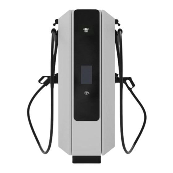
RFID card reader to be used when carrying out a charging session. The right and front view, from left to right, with the charger’s main components are shown below: Display CCS-1 CCS-1 Connector Connector Charging cable Charging cable Point of sale Emergency push-button RFID reader Ford Pro contact info: chargingsupport@fordpro.com and 1-800-34-FLEET... -
Page 18: Charging Process
Through the vehicle control system. • By the operator CPO charge point operator. Once the charging has stopped, the connector will be released. Replace the connector back to the appropriate dock on the charger. Ford Pro contact info: chargingsupport@fordpro.com and 1-800-34-FLEET... -
Page 19: Advanced Charge Functionality
• UL 2202: Electric Vehicle (EV) Charging System Equipment. • NEC - Article 625: Electric Vehicle Charging Systems. • FCC part 15 - class A: Unintentional radiators - industrial application. Ford Pro contact info: chargingsupport@fordpro.com and 1-800-34-FLEET... -
Page 20: Technical Characteristics
670 x 750 x 1800 / 2.2 x 2.5 x 5.9 Regulation UL 2202, NEC 625, FCC Part 15 Class A Consult with the manufacturer for more information about the connector overload capability. Consult with the manufacturer for further information. Ford Pro contact info: chargingsupport@fordpro.com and 1-800-34-FLEET... -
Page 21: Dimensions And Weight
1700 74.35 70.87 1.32 25.59 29.52 29.92 38.89 3.94 66.93 13.85 26.38 GENERAL DIMENSIONS GRAVITY CENTER 31.42 17.32 3.94 15.08 5.91 14.60 34.02 16.22 ACCESSIBLE ELEMENTS 1000 1019 20.96 8.86 39.37 32.48 40.12 Ford Pro contact info: chargingsupport@fordpro.com and 1-800-34-FLEET... - Page 22 14 / 30.86 This is an indicative value. For other equipment of the NB 120 range, consider the weight of each power module as of approximately 22.5 kg (496 lb.) or consult with the manufacturer. Ford Pro contact info: chargingsupport@fordpro.com and 1-800-34-FLEET...
-
Page 23: Handling And Transportation
Installer is responsible of deciding if the posts are installed within the standard period or otherwise, the installation date is to be defined. Ford Pro contact info: chargingsupport@fordpro.com and 1-800-34-FLEET... -
Page 24: Extended Storage
The equipment has a lifting tool with hoist rings located at the upper part of the tool. To lift them, slings must be attached to each ring. Also, the slings must be firmly attached to the crane. Ford Pro contact info: chargingsupport@fordpro.com and 1-800-34-FLEET... - Page 25 Be aware of all caution and warning messages before lifting the equipment. To lift the equipment, a sling or a chain must be attached to each ring and securely fastened to the crane. Ford Pro contact info: chargingsupport@fordpro.com and 1-800-34-FLEET...
- Page 26 Ensure that loading/lifting equipment has a greater capacity than the weight of the equipment plus the auxiliary elements and the loading/lifting task is carried out in a way that ensures the stability of the equipment. For more information about the opening equipment doors, refer to the "Access" section. Ford Pro contact info: chargingsupport@fordpro.com and 1-800-34-FLEET...
-
Page 27: Preparation For Installing The Equipment
• Do not install on floodplains, neither in places where objects can fall on. • The land should be provided with a drainage system, especially in locations with high water tables and/or heavy rainfall. Ford Pro contact info: chargingsupport@fordpro.com and 1-800-34-FLEET... - Page 28 Each charger must be anchored to a foundation which guarantees its stability towards vertical and horizontal actions. It is installer’s responsibility to design and build the foundation to guarantee stability of each equipment. Ford Pro contact info: chargingsupport@fordpro.com and 1-800-34-FLEET...
-
Page 29: Minimum Working Distances
Rear side distance: It does not require a special rear space; it can be installed in touch with a wall or other element. Ford Pro contact info: chargingsupport@fordpro.com and 1-800-34-FLEET... -
Page 30: Charging Cable Maneuverability
The picture below (top view) shows the cable range area in a parking lot where cars are parked in front of the post: Please note that this distance corresponds to outdoor and well-ventilated equipment. Ford Pro contact info: chargingsupport@fordpro.com and 1-800-34-FLEET... -
Page 31: Anchoring Of The Equipment
0.79 It is recommended to use an expansive anchoring M16x145, with a tightening torque of 120 Nm (manufacturer’s recommendation). To guarantee the proper fixing of the equipment, install a total of 4 anchors. Ford Pro contact info: chargingsupport@fordpro.com and 1-800-34-FLEET... -
Page 32: Ventilation System
Noise level The NB240 (and all its power levels) noise level is below 60 dB at 1 meter from the charger and below 56 dB at 2 meters. Consult with Ford for more information. Ford Pro contact info: chargingsupport@fordpro.com and 1-800-34-FLEET... -
Page 33: Cable Access And Connections
Ethernet cable (CAT5e or CAT6) with RJ45 terminals OR optional multimode optical fiber to each Dispenser (as applicable). Several factors can influence the choice of cable, including the distance between the distribution board and the power cabinet, the maximum input current, and the installation mode. Ford Pro contact info: chargingsupport@fordpro.com and 1-800-34-FLEET... -
Page 34: Access
To access the lower part, remove the front and rear bezel, see "Anchoring of the equipment". The space provided for the entry of the power and communications cables is shown in the following image (bottom view): Note: Use only the amount of cable glands needed for the project. Ford Pro contact info: chargingsupport@fordpro.com and 1-800-34-FLEET... - Page 35 (marked in red in the image above) may be required to allow the correct alignment of the cables. It is recommended to construct a small vault or pit in the foundation under the gland plates. This construction should not interfere with the anchoring of the charger. Ford Pro contact info: chargingsupport@fordpro.com and 1-800-34-FLEET...
- Page 36 Ethernet or fiber optic cable. A blank plate is included to suit individual site needs. Ford always recommends following the holes pattern shown below. If this is not possible, it is customer's responsibility to meet wire bending requirements.
-
Page 37: Connections
INPUT POWER SUPPLY (L1, L2, L3) MAXIMUM DIAMETER PERMITTED BY THE CABLE GLAND CABLE GLAND NB60 M40 (1-1/2") 28 mm (1.1 in.) NB90 M40 (1-1/2") 28 mm (1.1 in.) NB120 M40 (1-1/2") 28 mm (1.1 in.) Ford Pro contact info: chargingsupport@fordpro.com and 1-800-34-FLEET... - Page 38 The following picture shows the conductors for phases (L1, L2 and L3), neutral (N) and ground (PE). The following pictures show the distance from base to power terminals and from ground to the gland plates of the equipment. 101.5 318.5 341.5 405.5 3.99 12.54 10.79 13.44 15.19 15.96 Ford Pro contact info: chargingsupport@fordpro.com and 1-800-34-FLEET...
- Page 39 Use M10 (7/16”) bolts and nuts and apply the recommended torque according to the quality (See “Torque and screw sizing”). • Use a spring washer and a fender washer between the nuts or bolts head and the busbar or terminal lug. Ford Pro contact info: chargingsupport@fordpro.com and 1-800-34-FLEET...
- Page 40 DC Charger NB 120 Installation Manual Communications connection Ford recommends connecting the equipment via 4G as the preferred option, Wi-Fi as the second option and Ethernet as the last option. Ethernet requirements (if needed) • Recommended cable size: Ethernet CAT 5e or CAT 6 UTP - RJ45 Connection Switch.
- Page 41 Before opening any door, the equipment must be completely isolated, without any voltage. Be sure to follow the insulation guidelines and all safety instructions indicated in the "Safety instructions" section. Please use the indicated PPE to prevent an electric shock. Ford Pro contact info: chargingsupport@fordpro.com and 1-800-34-FLEET...
-
Page 42: Protections
The equipment includes the following protections: Nominal Nominal Breaking Type current (I voltage (U capacity (kA) Power modules 3-phases 63 A 480 V 6 kA Auxiliary circuit 10 A 480 V 10 kA Ford Pro contact info: chargingsupport@fordpro.com and 1-800-34-FLEET... -
Page 43: Interface
• Touch screen: Allows selecting some characteristics of the charger and the charging options, ending the session, as well as displaying the charging status or fault messages. • Charger status indicator: It is displayed on the display, located on the glass face of each charger. Ford Pro contact info: chargingsupport@fordpro.com and 1-800-34-FLEET... - Page 44 LED will no longer be illuminated and will switch to the "Off" state. If the "ALM" LED is fix or flashing, this indicates an abnormal state. RUN (green) If ON, it indicates the power module is being energized. Ford Pro contact info: chargingsupport@fordpro.com and 1-800-34-FLEET...
-
Page 45: Communications
Before opening any door, the equipment must be completely isolated, without any voltage. Be sure to follow the insulation guidelines and all safety instructions indicated in the "Safety instructions" section. Please use all the indicated PPE. Otherwise, you may get an electric shock. Ford Pro contact info: chargingsupport@fordpro.com and 1-800-34-FLEET... -
Page 46: Communication
For communication via 4G a MicroSIM card is pre-installed into the indicated charger control card slot: If it is necessary to replace the MicroSIM, consult Ford for further information regarding its configuration. The following table shows the main 4G communication characteristics:... -
Page 47: Ethernet Communication
The equipment requires an Ethernet entry connection for OCPP1.6 communications and internet connection. Note that this connection is not necessary if communication is established via 4G, or Wi-Fi, for more information see section "Communication via 4G". Ford Pro contact info: chargingsupport@fordpro.com and 1-800-34-FLEET... -
Page 48: Loto Procedure
Otherwise, the equipment could get damaged, and personnel get seriously injured. The instructions in this manual do not replace or local or national regulations. It is the user's responsibility to comply with all safety standards that apply at the installation site. Ford Pro contact info: chargingsupport@fordpro.com and 1-800-34-FLEET... -
Page 49: Equipment Status
Use appropriate equipment for DC power measures. It is responsibility of the technical personnel to have their tools calibrated and in good conditions. Always wear the PPE according to electric risk and to the current Health and Safety regulations. Ford Pro contact info: chargingsupport@fordpro.com and 1-800-34-FLEET... -
Page 50: Loto Actions
LOTO actions are removed. Follow the “check points for absence of voltage”. After all these actions, status 2 is reached on the charger. Refer to "Equipment status" section for further information about equipment status. Ford Pro contact info: chargingsupport@fordpro.com and 1-800-34-FLEET... -
Page 51: Check Points For Absence Of Voltage
Use appropriate equipment for DC power measures. It is responsibility of the technical personnel to have their tools calibrated and in good condition. Always wear the PPE according to electric risk and to the current OSHA regulations. Ford Pro contact info: chargingsupport@fordpro.com and 1-800-34-FLEET... - Page 52 (disconnectors). Under no circumstances any of these components must be manually operated when the equipment is energized. Follow the LOTO actions in the inverse order to remove LOTO actions. Ford Pro contact info: chargingsupport@fordpro.com and 1-800-34-FLEET...
-
Page 53: Commissioning
The instructions in this manual do not replace local or national regulations. It is the responsibility of the user to comply with all applicable safety standards at the installation site. Contact Ford prior to starting up the equipment for commissioning. Ford Pro contact info: chargingsupport@fordpro.com and 1-800-34-FLEET... -
Page 54: Safe Stop
With the appropriate PPE, check the absence of voltage at the AC input. Restrict unauthorized access to the work area. Ford Pro contact info: chargingsupport@fordpro.com and 1-800-34-FLEET... -
Page 55: Emergency Stop And Restart
Do not use the emergency stop pushbutton to perform regular stops on the charger. It should only be used when an emergency occurs. Otherwise, longevity of the main components could be shortened and result in equipment damage. Ford Pro contact info: chargingsupport@fordpro.com and 1-800-34-FLEET... -
Page 56: Maintenance
Also, local and national electrical regulations must be followed to avoid personal injury and/or damage to the equipment. Failure to comply with safety instructions and electrical codes may void the warranty. Ford Pro contact info: chargingsupport@fordpro.com and 1-800-34-FLEET... -
Page 57: Checklist
Internal cleaning. Filters - visual check and replacement. Doors condition. Cables and conductors - visual and manual check. External and internal tightening torques - manual check. Control circuit and protections - manual check. Ford Pro contact info: chargingsupport@fordpro.com and 1-800-34-FLEET... -
Page 58: Status 1
If the charge test is performed, it is the personnel responsibility to ensure the presence of an electric vehicle to perform the charging procedure with each connector. If the charge test is performed, the costs derived from it must be assumed by the customer. Ford Pro contact info: chargingsupport@fordpro.com and 1-800-34-FLEET... -
Page 59: Status 2
4. Cables and conductors Visual inspection of cables and terminals. Check the cables are in good condition and sealed. Check that the connectors and terminals are correctly inserted and there are no visual signs of overheating. Ford Pro contact info: chargingsupport@fordpro.com and 1-800-34-FLEET... - Page 60 6. Control circuit and protections Check if overvoltage protectors are operational. Visually check the fuses to guarantee they are not blown. Check the good condition of the control cards, as well as its connections. Ford Pro contact info: chargingsupport@fordpro.com and 1-800-34-FLEET...
Need help?
Do you have a question about the PRO NB 120 Series and is the answer not in the manual?
Questions and answers