Table of Contents
Advertisement
Advertisement
Table of Contents

Subscribe to Our Youtube Channel
Related Manuals for Ford Pro AC Charging Station 80A


Summary of Contents for Ford Pro AC Charging Station 80A
- Page 1 Ford Pro AC Charging Station 80A Installation Manual v1.8...
-
Page 3: Table Of Contents
4.1 Charging status indicators ............27 4.2 Charging an Electric Vehicle (EV) ........... 28 4.3 Stop charging ................. 28 4.4 General care ................29 4.5 Customer support ..............29 4.6 Limited Warranty ..............30 Ford Pro contact info: chargingsupport@fordpro.com and 1-800-34-FLEET... -
Page 4: Important Safety
This document provides instructions for the Electric Vehicle Supply Equipment (EVSE) and should not be used for any other product. Repair and Maintenance Clause Ford Pro contact info: chargingsupport@fordpro.com and 1-800-34-FLEET... - Page 5 Changes or modifications not covered in this guide must be approved in writing by the manufacturer’s Regulatory Engineering Department. Changes or modifications made without written approval may void the user’s authority to operate this equipment. Ford Pro contact info: chargingsupport@fordpro.com and 1-800-34-FLEET...
- Page 6 Do not use extender cables to increase the length of the charging cable. Maximum length is limited to 25 feet by the National Fire Protection Agency. WARNING: RISK OF PERSONAL INJURY Do not drag this equipment by input power cord. Ford Pro contact info: chargingsupport@fordpro.com and 1-800-34-FLEET...
- Page 7 It should not locate in a recessed area or below floor level. Automatic reset feature provided. WARNING: RISK OF FIRE OR EXPLOSION Do not use this device with an extension cord. Ford Pro contact info: chargingsupport@fordpro.com and 1-800-34-FLEET...
-
Page 8: Introduction
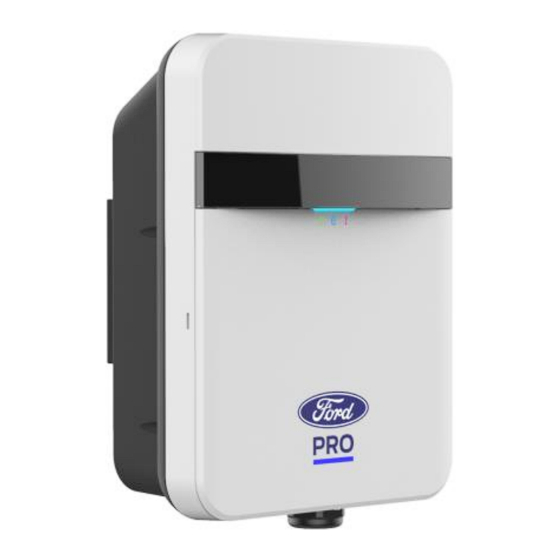
SAVE THESE INSTRUCTIONS 1 Introduction This user manual applies to “80A Level 2 AC Charger for Plug-in Electric Vehicles (PEVs) and Battery Electric Vehicles (BEVs)”. !!! Any unauthorized modifications will void the manufacturer’s warranty!!! Ford Pro contact info: chargingsupport@fordpro.com and 1-800-34-FLEET... - Page 9 US Type Charger 80A Installation Manual Product View Figure 1-1 Front view Box Contents Inside the box, you will find the following accessories. Ford Pro contact info: chargingsupport@fordpro.com and 1-800-34-FLEET...
- Page 10 With Hook x1, Holster x1, Holster ASSY M4xL15 tapping screw x2 #2 AWG Ring terminal lug x 2, Accessory Bag #8 AWG Ring terminal lug, M6 machine screw x1 Carton Opening Process Ford Pro contact info: chargingsupport@fordpro.com and 1-800-34-FLEET...
- Page 11 US Type Charger 80A Installation Manual Open the carton and remove the EPE Foam. Figure 1-3 Opening the carton Figure 1-4 Charge point device Ford Pro contact info: chargingsupport@fordpro.com and 1-800-34-FLEET...
- Page 12 US Type Charger 80A Installation Manual 2. Take out the charge point and then remove the mounting bracket before installing it. Figure 1-5 Take out the charge point Figure 1-6 Remove the mounting bracket Ford Pro contact info: chargingsupport@fordpro.com and 1-800-34-FLEET...
-
Page 13: Specification
OCPP 1.6 -35 ~ 55 ℃ (-31 to 131℉) Operation Temp. (50~55 ℃ derating, Max. current 60A) -40 ~ 80 ℃ (-40 to 176℉) Storage Temp. Maximum Operating 3500m above sea level Altitude Ford Pro contact info: chargingsupport@fordpro.com and 1-800-34-FLEET... -
Page 14: Installation
CAUTION: Avoid touching or pressing the OLED screen all times, as this may result in damage to the OLED screen. DANGER: RISK OF SUFFOCATION Ford Pro contact info: chargingsupport@fordpro.com and 1-800-34-FLEET... -
Page 15: Tools & Parts Required For Installation
Hold EV charging plug ASSY Screw Tapping: Fasten Mounting Bracket & Holster Mechanical : M6 Mechanical Fasten charge point & : M6 Mount Bracket Wire, 2 AWG x 2, Copper 8AWG x 1 (for Ford Pro contact info: chargingsupport@fordpro.com and 1-800-34-FLEET... -
Page 16: Charge Point Installation
Conduit 1 inch Protect power cable Philips Screwdriver Torx Security Screwdriver Bit T20 Hexagon 5/16 Tighten #12 Tapping Socket screws Torque 40 kgf-cm Wrench 3.3 Charge Point Installation 3.3.1 Disassemble top cover Ford Pro contact info: chargingsupport@fordpro.com and 1-800-34-FLEET... - Page 17 US Type Charger 80A Installation Manual Figure 3-1 Loosen 1 pc M4 screw. Figure 3-2 Use flat tip screwdriver to push snap then open front cover. Ford Pro contact info: chargingsupport@fordpro.com and 1-800-34-FLEET...
- Page 18 The mounting bracket has ten screw holes. If only two screws be used to fasten the mounting bracket, the screws should pass through the middle two screw holes of the mounting bracket. The other screw holes are reserved for the user. Ford Pro contact info: chargingsupport@fordpro.com and 1-800-34-FLEET...
- Page 19 1. Put the charge point on the mounting bracket. 2. Fasten charge point on mounting bracket by tightening M6 screw. 3. Please refer to the following torque. Screw Torque 31 kgf.cm 26.9 lbf·in Ford Pro contact info: chargingsupport@fordpro.com and 1-800-34-FLEET...
- Page 20 US Type Charger 80A Installation Manual Figure 3-6 Charge point and mounting bracket Ford Pro contact info: chargingsupport@fordpro.com and 1-800-34-FLEET...
-
Page 21: Input Power Cord Installation
Installation Manual Figure 3-7 Tighten M6 screw 3.4 Input Power Cord Installation 1. Choose the appropriate conduit in accordance with all applicable state, local and National Electrical Codes and standards. Figure 3-8 Conduit Ford Pro contact info: chargingsupport@fordpro.com and 1-800-34-FLEET... - Page 22 Refer to local AHJ wiring requirements. (Typically, THHN, THWN-2, or XHHW-2) Model Terminal Conductor Rating L1, L2 2 AWG Basic/smart/intelligent copper Charger-80A 8 AWG wire Figure 3-10 Copper terminal, heat shrink tube and copper wire Ford Pro contact info: chargingsupport@fordpro.com and 1-800-34-FLEET...
- Page 23 CAUTION: If this unit is installed outdoors, the outlet must be rated for outdoor installation. The outlet must be installed properly to maintain the proper NEMA rating of the enclosure. 2-5. Lock the conduit on the enclosure. Please refer to the following torque. Ford Pro contact info: chargingsupport@fordpro.com and 1-800-34-FLEET...
-
Page 24: Adjust Max. Output Current
15 kgf·cm 13 lbf·in 3.5 Adjust Max. Output Current Please contact Ford Pro to offer remote current derate support. 1. Adjust Max. Output Current from Web Portal Figure 3-12 Modify Current in Max. Amperage FW Setting field and press “Apply”... -
Page 25: Holster Installation
2. Fasten the hook on the wall with appropriate screws. 2-1. For finished walls supported by wood studs, use 2pcs screws (#12 tapping or M6 ) . 2-2. The recommend torque is 25 kgf.cm (21.7 lbf·in). Figure 3-14 Secure the hook Ford Pro contact info: chargingsupport@fordpro.com and 1-800-34-FLEET... - Page 26 US Type Charger 80A Installation Manual 3. Make the holster face up and combine with the hook. Figure 3-15 Secure the holster 4. Rotate the holster down. Figure 3-16 Rotate the holster Ford Pro contact info: chargingsupport@fordpro.com and 1-800-34-FLEET...
- Page 27 5-1. The recommend torque is 6 kgf.cm (5.2 lbf·in). The screws make the holster ASSY firm. Figure 3-17 Tighten screws 6. Place EV charging plug on the holster. Figure 3-18 Place EV charging plug Ford Pro contact info: chargingsupport@fordpro.com and 1-800-34-FLEET...
-
Page 28: Operations
Authorized, wait for EV Green Flashing Connect Flashing green (Slow): Suspend (Occupying) Flashing blue (Slow): Blue Flashing Charging Red Steady Unrecoverable Fault Red Flashing Recoverable Fault Booting / Firmware Yellow Flashing Upgrading / Out of Service Ford Pro contact info: chargingsupport@fordpro.com and 1-800-34-FLEET... -
Page 29: Charging An Electric Vehicle (Ev)
Status indicator lights remain flashing RED until the error condition is resolved. • Temporary error conditions included: Over Current, Over Voltage, Under Voltage, and Over Temperature. Ford Pro contact info: chargingsupport@fordpro.com and 1-800-34-FLEET... -
Page 30: General Care
Ensure the power cable is stored on the cable hanger after use to avoid damage. • If the power cable or the charging plug is damaged, please contact Customer Support for replacement. 4.5 Customer support Please visit fordpro.com for additional customer support. Ford Pro contact info: chargingsupport@fordpro.com and 1-800-34-FLEET... -
Page 31: Limited Warranty
US Type Charger 80A Installation Manual 4.6 Limited Warranty The Limited Warranty associated with your charger is subject to certain exception and exclusions. For the terms of the limited warranty please visit FordPro.com. Ford Pro contact info: chargingsupport@fordpro.com and 1-800-34-FLEET... - Page 32 US Type Charger 80A Installation Manual Ford Pro contact info: chargingsupport@fordpro.com and 1-800-34-FLEET...
- Page 33 Chargeur de type américain-80A Manuel d'utilisation Rev 1.8...
Need help?
Do you have a question about the Pro AC Charging Station 80A and is the answer not in the manual?
Questions and answers