
Related Manuals for Ford Pro 2 Series


Summary of Contents for Ford Pro 2 Series
- Page 1 Ford Pro™ AC Charging Station 80A Series 2 Installation Manual Electric Vehicle Charging Station Model No. FPC-AC0080ZC-U** Issue C Ford Public...
- Page 2 This page intentionally left blank.
-
Page 3: Revision History
80A Charging Station Series 2 Installation Manual Revision History Affected Issue Date Description of Changes Pages 9.12.23 Initial Release 10.05.23 Updated formatting and style, added images, added warnings, updated verbiage, added dimensions, up- dated text, and removed ethernet instruction Added revision history, updated style elements, add- 4.24.24 ed confidential and internal markings, added content Public... -
Page 4: Table Of Contents
80A Charging Station Series 2 Installation Manual Table of Contents 1. Introduction ......................09 1.1. Overview ...........................09 1.2. Box Contents........................10 1.3. Product Specifications ....................10 2. Important Safety Instructions ................13 2.1. Repair and Maintenance Clause ................13 2.2. Federal Communication Commission Interference Statement ....... 14 2.3. - Page 5 80A Charging Station Series 2 Installation Manual Table des Matières 1. Introduction ......................41 1.1. Vue d’Ensemble ....................... 41 1.2. Contenu de la Boîte ..................... 42 1.3. Spécifications du Produit .................... 42 2. CONSIGNES DE SÉCURITÉ IMPORTANTES ............ 45 2.1. Clause de Réparation et D’entretien ............... 45 2.2.
- Page 6 80A Charging Station Series 2 Installation Manual This page intentionally left blank. Public...
- Page 7 80A Charging Station Series 2 Installation Manual Figures Figure 1.1 Ford Pro™ AC Charging Station 80A (Series 2) Overview .......09 Figure 1.2 Ford Pro™ AC Charging Station 80A (Series 2) Dimensions ....09 Figure 1.3 Box Contents .......................10 Figure 3.1 Open the Box ....................... 19 Figure 3.2 Unpack the Charger ..................
- Page 8 80A Charging Station Series 2 Installation Manual Schémas Schéma 1.1 Vue de Face ...................... 41 Schéma 1.2 Dimensions de la borne de recharge Ford Pro™ CA de 80 A (Série 2) ..............................41 Schéma 1.3 Contenu de la Boîte ..................42 Schéma 3.5 Ouverture de la Boîte ..................
-
Page 9: Introduction
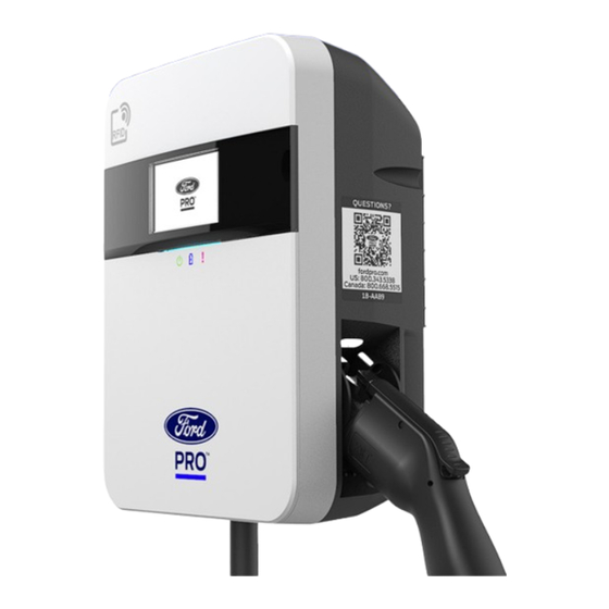
80A Charging Station Series 2 Installation Manual 1. Introduction 1.1. Overview This user manual applies to Ford Pro™ AC Charging Station 80A (Series 2). Any unauthorized modifications will void the product warranty. Figure 1.1 Ford Pro™ AC Charging Station 80A (Series 2) Overview 10.65”... -
Page 10: Box Contents
80A Charging Station Series 2 Installation Manual 1.2. Box Contents Inside the box, you will find the following components. 1 4 6 Amperage Reduc on Label / É que e de réduc on d'ampérage CHARGING STATION M4 x 8 In/Out (Dans/Dehors): 208-240VAC, 1Ø, 50/60Hz, Max.80A Type: Type 4 Enclosure Taper: Type 4 Enclos... - Page 11 * Cellular is pre-configured on the charger. If cellular connection is not avail- able, the charger can be configured to Ethernet and / or Wi-Fi if available. If you need assistance with this, contact Ford Pro™ Charging at 1-800-343-5338. Public...
- Page 12 80A Charging Station Series 2 Installation Manual This page intentionally left blank. Public...
-
Page 13: Important Safety Instructions
80A Charging Station Series 2 Installation Manual 2. Important Safety Instructions SAVE THIS INSTRUCTION This document contains instructions and warnings which must be followed when installing and using the Electric Vehicle Supply Equipment (Charger). Before in- stalling or using the Charger, read this entire document as well as WARNING and CAUTION markings in this document. -
Page 14: Federal Communication Commission Interference Statement
80A Charging Station Series 2 Installation Manual 2.2. Federal Communication Commission Interference Statement This equipment complies with part 15 of the FCC rules. Operation is subject to the following two conditions: (1) This equipment may not cause harmful interference, and (2) this equipment must accept any interference received, including interfer- ence that may cause undesired operation. - Page 15 80A Charging Station Series 2 Installation Manual WARNING RISK OF PERSONAL INJURY Do not use extender cables to increase the length of the charging cable. Maximum length is limited to 25 feet by the National Fire Protection Agency. WARNING RISK OF ELECTRIC SHOCK Improper connection of the equipment grounding conductor can result in a risk of electric shock.
-
Page 16: Lockout/Tagout Procedure (Loto)
80A Charging Station Series 2 Installation Manual CAUTION RISK OF DAMAGE TO THE EQUIPMENT Do not operate this equipment in temperatures outside its operating range of -40°F to +122°F (-40°C to +50°C). CAUTION RISK OF DAMAGE TO THE EQUIPMENT Store this equipment in a clean dry place in temperatures between -40°F to +176°F (-40°C and +80°C). -
Page 17: Pre-Installation Safety Check
80A Charging Station Series 2 Installation Manual Step 6. Verify Isolation Ensure the charger is powered OFF. There should be no LED lights on, screen dis- play should be dark/empty, and no power should be available when the connector is plugged into an EV or EV simulator. Step 7. -
Page 18: Grounding Instructions
80A Charging Station Series 2 Installation Manual 2.7. Grounding Instructions The charger must have equipment grounding, adhering to NEC 250.56, through a permanent wiring system or an equipment grounding conductor. Use a dedicated grounding wire and connect to the equipment ground terminal block for ground- ing. -
Page 19: Unboxing
80A Charging Station Series 2 Installation Manual 3. Unboxing Procedure 1. Box Opening Process Step 1. Open the box and remove the upper plate. Figure 3.1 Open the Box Figure 3.2 Unpack the Charger Public... -
Page 20: Figure 3.3 Remove The Charger
80A Charging Station Series 2 Installation Manual Step 2. Take out the charger. Figure 3.3 Remove the Charger Public... -
Page 21: Charger Installation
80A Charging Station Series 2 Installation Manual 4. Charger Installation Step 1. Disassemble top cover. Figure 4.1 Loosen 1 pc M4 Screw Figure 4.2 Push Front Cover Down, Then Pull it Off Charger Public... -
Page 22: Figure 4.3 Loosen (8) M4 Screws To Open Interior Install Cover
80A Charging Station Series 2 Installation Manual Step 2. Remove interior install cover. (8) M4 Screws Figure 4.3 Loosen (8) M4 Screws to Open Interior Install Cover Figure 4.4 Remove M6 Screw Public... -
Page 23: Figure 4.5 Remove The Mounting Bracket
80A Charging Station Series 2 Installation Manual Step 3. Remove the mounting bracket by sliding the bracket down and off the charger. Figure 4.5 Remove the Mounting Bracket Step 4. Secure the main body mounting bracket to the wall with appropriate screws. -
Page 24: Figure 4.7 Secure Charger To Mounting Bracket
80A Charging Station Series 2 Installation Manual Screw sizing suggestion: • For masonry walls, use M6 mechanical screws. (Commercially Available) • For finished walls supported by wood studs, use #12 tapping screws. • Refer to the following screw torque guide. The actual torque is according to the wall material. -
Page 25: Input Power Cord Installation
80A Charging Station Series 2 Installation Manual Fasten charger on mounting bracket by tightening M6 screw. Figure 4.8 Fasten M6 Screw Refer to the following screw torque guide. Screw Length Torque 14mm 31 kgf.cm 27 lbf·in 4.1. Input Power Cord Installation Step 6. -
Page 26: Figure 4.10 Cable Input Position
The size of the ferrule depends on the size of power wiring size. Use the appropriate ferrule size. Model Terminal Conductor Rating 2 AWG Ford Pro™ AC L1, L2 Max wire size #2 90°C copper wire Charging Station 80A (series 2) 8 AWG... - Page 27 80A Charging Station Series 2 Installation Manual Table 4.5 Wire Gauge to Ferrule Type Rigid Stranded Flexible Stranded Wire Class I Gauge Class B Class C Class G Class H Class K Compact (DLO) Number of strands Sample Recommended If ferrule is used, use UL certified ferrule w/ UL certified crimping tool Example: Z+F ferrule (V30AE000033) for 2 AWG wire...
-
Page 28: Figure 4.11 Ferrule Use
80A Charging Station Series 2 Installation Manual If use flexible stranded wire with ferrule, make sure all wire strands are contained in the ferrule. Figure 4.11 Ferrule Use Step 8. Lock the conduit on the enclosure. Refer to the following torque. Conduit Torque 1 “... -
Page 29: Adjust Max. Output Current (Optional)
80A Charging Station Series 2 Installation Manual Step 10. Use the following torque to connect the wire to the terminal block. Screw Torque 94 lbf·in 108 kgf-cm Hex 3/16 40 lbf·in 46kgf-cm 10~14 35 lbf·in 40 kgf-cm WARNING RISK OF FIRE OR EXPLOSION To reduce the risk of fire, connect only to a circuit provided with the required branch circuit overcurrent protection in accordance with the National Electrical Code, ANSI/NFPA 70, and the Canadian Electrical... -
Page 30: Figure 4.13 Rotary Switch Location
80A Charging Station Series 2 Installation Manual Step 11. Configure the rotary switch to set the Max. output current. Default factory setting is 80A. Figure 4.13 Rotary Switch Location Turn OFF power. Use a flathead screwdriver to adjust the rotary switch configuration appro- priate for the installed circuit breaker. -
Page 31: Figure 4.14 Rotary Switch Label Sticker On The Interior Install Cover
80A Charging Station Series 2 Installation Manual If the charger is installed on a circuit breaker smaller than 100A, the rotary switch should be adjusted to limit charger output to less than or equal to 80% of the cir- cuit breakers rating. (E.g.: For a 60A circuit breaker, the charger output limit should be adjusted to no more than 48A.) If needed, Amperage Reduction Labels are avail- able to place on charger and circuit breaker. -
Page 32: Installation Completion
80A Charging Station Series 2 Installation Manual 4.3. Installation Completion Step 14. Install front cover then fasten M4 screw. Figure 4.15 Loosen 1 pc M4 Screw Screw Length Torque 12mm 8 kgf.cm 6.9 lbf·in Step 15. Stick the product label over the main label to cover up the original In/ Out information. -
Page 33: Operations
5.2. RFID Access Control Management RFID Access Control is an optional software feature on the chargers. Reach out to Ford Pro™ Charging fordpro.com for customer support options to Purchase RFID Cards and to Add, Activate, & De-Activate RFID cards from Account or Assign/Asso- ciate RFID cards to Charging Depot. -
Page 34: Stop Charging
80A Charging Station Series 2 Installation Manual 5.4.1. Operation for Charger as Shipped Release charging connector from holster. Insert the charging connector into the EV. Charging session started. Figure 5.1 Connect the Charging Connector to the EV 5.4.2. If RFID Access Control is enabled on your charger, then you will authorize charge session by RFID Card (Authorize first and then plug) Swipe card. -
Page 35: General Care
80A Charging Station Series 2 Installation Manual 5.5.1. Auto Restart When a charging session is interrupted due to a temporary error condition, the charger will automatically restart charging when the cause of the temporary error condition returns to normal. Status indicator lights remain flashing RED until the error condition is resolved. -
Page 36: Installer Check List
Ford Pro™ cannot guarantee the accuracy of the information collected in this form. Neither Ford Motor Company nor Ford Pro™ shall be responsible for completion or verification of the form, or any costs or expenses related to completing this form or verifying the information provided. -
Page 37: Electrical Information
What is the total amperage of the panel to which the charger is con- nected? Is this panel dedicated just to your Ford EV chargers? Max Current Switch Setting, if appli- cable (if your charger has a hard- ware dip-switch, what is the current setting?) Electrical Information Specifics –... -
Page 38: Testing Information
80A Charging Station Series 2 Installation Manual 5. Testing Information Has the charger been tested to verify connectivity? Has the charger been tested to verify it charges a vehicle successfully? Additional Notes or Comments 6. Inspection Information Has the installation passed any required inspections? If so what date: ... - Page 39 80A Charging Station Series 2 Installation Manual Canadian French Installation Manual Manuel d’Installation en Français Canadien Public...
- Page 40 80A Charging Station Series 2 Installation Manual Cette page est intentionnellement laissée vide. Public...
-
Page 41: Introduction
80A Charging Station Series 2 Installation Manual 1. Introduction 1.1. Vue d’Ensemble Ce manuel d’utilisation s’applique au Ford Pro™ Chargeur CA 80A (Série 2). Toute modification non autorisée annulera la garantie du fabricant. Schéma 1.1 Vue de Face 10.65” 27.1cm... -
Page 42: Contenu De La Boîte
80A Charging Station Series 2 Installation Manual 1.2. Contenu de la Boîte À l’intérieur de la boîte, vous trouverez les accessoires suivants. 1 4 6 Amperage Reduc on Label / É que e de réduc on d'ampérage CHARGING STATION M4 x 8 In/Out (Dans/Dehors): 208-240VAC, 1Ø, 50/60Hz, Max.80A... - Page 43 * La connexion cellulaire est préconfigurée sur le chargeur. Si aucune connexion cellulaire n’est disponible, la borne peut être configurée par Ethernet et (ou) Wi-Fi, si disponible. Si vous avez besoin d’as- sistance, communiquez avec les Solutions de recharge Ford Pro au 1 800 34-FLEET. Public...
- Page 44 80A Charging Station Series 2 Installation Manual Cette page est intentionnellement laissée vide. Public...
-
Page 45: Consignes De Sécurité Importantes
80A Charging Station Series 2 Installation Manual 2. CONSIGNES DE SÉCURITÉ IMPORTANTES Ce document contient des instructions et des avertissements qui doivent être respectés lors de l’installation et de l’utilisation de l’équipement d’alimentation du véhicule électrique (Charger). Avant d’installer ou d’utiliser l’Charger, lisez l’in- tégralité... -
Page 46: Déclaration D'industrie Canada
80A Charging Station Series 2 Installation Manual Cet équipement a été testé et déclaré conforme aux limites d’un appareil numérique de classe B, conformément à la partie 15 des règles de la FCC. Ces lim- ites sont conçues pour fournir une protection raisonnable contre les interférences nuisibles dans une installation résidentielle. - Page 47 80A Charging Station Series 2 Installation Manual AVERTISSEMENT RISQUE DE BLESSURES CORPORELLES Ne pas traîner cet équipement par le câble d’alimentation. AVERTISSEMENT RISQUE DE CHOC ÉLECTRIQUE Les précautions de base doivent toujours être respectées lors de l’utilisation de produits électriques, notamment les suiva- ntes: •...
-
Page 48: Procédure De Cadenassage Et D'étiquetage
80A Charging Station Series 2 Installation Manual AVERTISSEMENT RISQUE D’INCENDIE OU D’EXPLOSIONZ N’utilisez pas cet appareil avec une rallonge. ATTENTION RISQUE D’ENDOMMAGEMENT DE L’APPAREIL N’utilisez pas cet équipement à des températures situées en dehors de sa marge de tolérance de -40°F à +121°F (-40°C à +50°C). ATTENTION RISQUE D’ENDOMMAGEMENT DE L’APPAREIL Conservez cet équipement dans un endroit propre et sec à... -
Page 49: Contrôle De Sécurité Avant L'installation
80A Charging Station Series 2 Installation Manual Étape 4. Mettre en place le dispositif de cadenassage et d’étiquetage sur l’équi- pement Pour éviter que l’équipement soit utilisé ou remis en marche par inadvertance, mettez en place tout dispositif de cadenassage et d’étiquetage nécessaire. Cela comprend un cadenas pour maintenir le dispositif d’alimentation à... -
Page 50: Instructions De Mise À La Terre
80A Charging Station Series 2 Installation Manual ATTENTION RISQUE D’ENDOMMAGEMENT DE L’APPAREIL Évitez de toucher l’écran ACL, car vous pourriez l’endommager. ATTENTION RISQUE D’ENDOMMAGEMENT DE L’APPAREIL N’utilisez pas de rallonge. Avant d’installer le chargeur, assurez-vous d’avoir lu toutes les instructions de ce manuel et de bien comprendre son contenu. -
Page 51: Outils & Pièces Nécessaires À L'installation
80A Charging Station Series 2 Installation Manual 2.8. Outils & Pièces Nécessaires à L’installation Tableau 2.2 Outils & Pièces Nécessaires à L’installation Outil QTÉ Modèle Taille Incl. Remarque Support de 222x173x9 Fixer le chargeur à la surface de montage montage Taraudage: Fixer le support de montage Mécanique:... - Page 52 80A Charging Station Series 2 Installation Manual Cette page est intentionnellement laissée vide. Public...
-
Page 53: Ouverture De La Boîte
80A Charging Station Series 2 Installation Manual 3. Ouverture de la Boîte Processus 4. D’ouverture de la Boîte Ouvrez la boîte et retirez la plaque supérieure. Schéma 3.5 Ouverture de la Boîte Schéma 3.6 Déballez la Boîte Public... - Page 54 80A Charging Station Series 2 Installation Manual Retirez le chargeur. Schéma 3.7 Retirez le chargeur Public...
-
Page 55: Installation Du Chargeur
80A Charging Station Series 2 Installation Manual 4. Installation du Chargeur Step 1. Démonter le couvercle supérieur. Schéma 4.1 Desserrez 1 vis M4 Schéma 4.2 Tirez vers le bas le couvercle frontal, puis dégagez-le partiellement du chargeur Public... - Page 56 80A Charging Station Series 2 Installation Manual Étape 2. Retirer le couvercle intérieur. (8) M4 Schéma 4.3 Desserrez les 8 vis M4 et Ouvrez le Couvercle de L’installation Schéma 4.4 Retirez la vis M6 Public...
- Page 57 80A Charging Station Series 2 Installation Manual Étape 3. Retirer le support de montage en le faisant glisser vers le bas de la borne de recharge. Schéma 4.5 Retirez le Support de Montage Étape 4. Fixez le support de montage du corps principal au mur avec la vis appro- priée.
- Page 58 80A Charging Station Series 2 Installation Manual Suggestion de dimensions des vis: • Pour les murs en maçonnerie, utilisez des vis mécaniques M6. (Disponible dans le com- merce) • Pour les murs finis soutenus par des montants en bois, utilisez des vis à tôle #12. (Modèle d’accessoires) •...
-
Page 59: Installation Du Câble D'alimentationd'entrée
80A Charging Station Series 2 Installation Manual Fixer le chargeur sur le support de montage en serrant la vis M6. Schéma 4.8 Fixer la Vis M6 Veuillez vous référer au couple suivant. Longueur Couple 14mm 31 kgf.cm 27 lbf·in 4.1. Installation du câble d’alimentationd’entrée Étape 6. - Page 60 La taille de la virole dépend de la taille du câblage d’alimentation. Utili- sez la taille de virole appropriée. Modèle Terminal Conducteur Classement 2 AWG Ford Pro™ Char- L1, L2 Taille maximale du Fil de cuivre 90 °C geur CA 80A (Série fil #2 8 AWG...
- Page 61 80A Charging Station Series 2 Installation Manual Table 4.4 Calibre de Fil Correspondant au Type de Virole Toronné rigide Toronné flexible Calibre Classe I de fil Classe B Classe C Classe G Classe H Classe K compact (DLO) Nombre de brins 8 6 4 2 Échantillon Recommandé...
- Page 62 80A Charging Station Series 2 Installation Manual Si vous utilisez un fil toronné flexible avec une virole, assurez-vous que tous les brins du fil sont contenus dans la virole. Schéma 4.11 Utilisation de Virole Étape 8. Verrouillez le conduit sur le boîtier. Veuillez vous référer au couple suiv- ant.
-
Page 63: Ajuster Le Courant De Sortie Maximum
80A Charging Station Series 2 Installation Manual Couple 94 lbf·in 108 kgf-cm Hex 3/16 40 lbf·in 46 kgf-cm 10~14 35 lbf·in 40 kgf-cm AVERTISSEMENT RISQUE D’INCENDIE OU D’EXPLOSION Pour réduire les risques d’incendie, connectez l’appareil uniquement à un circuit équipé d’une protection contre les surintensités de 100 ampères maximum, conformément au National Electrical Code, ANSI/NFPA 70, et au Code Canadien de l’électricité, Partie I, C22.2. - Page 64 80A Charging Station Series 2 Installation Manual Étape 10. Configurez le commutateur rotatif pour régler le courant de sortie maximal. Le réglage d’usine par défaut est 80A. Schéma 4.13 Emplacement du Commutateur Rotatif Coupez l’alimentation. Utilisez un tournevis à tête plate pour ajuster la configuration du commuta- teur rotatif appropriée au disjoncteur installé.
- Page 65 80A Charging Station Series 2 Installation Manual Étape 11. Réinstallez le couvercle intérieur. Enclosure Interior – Top Step 12. Collez l’étiquette de réduction d’ampérage sur le chargeur Rotary switch Label (8A0VP2) Si vous devez régler le courant de votre borne de recharge en dessous de la valeur (UL Outdoor) maximale, utilisez l’étiquette correspondant à...
-
Page 66: Fin De L'installation
80A Charging Station Series 2 Installation Manual 4.3. Fin de l’installation Étape 13. Ré-assemblez le le couvercle avant, puis fixezla vis M4. Schéma 4.15 Desserrez 1 vis M4 Longueur Couple 12mm 8 kgf.cm 6.9 lbf·in Étape 14. Collez l’étiquette du produit sur l’étiquette principale pour couvrir les informations d’entrée/sortie d’origine. -
Page 67: Opérations
5.1. Gestion du contrôle d’accès par RFID Le contrôle d’accès par RFID est une fonction logicielle disponible en option sur les chargeurs. Vous pouvez consulter le site fordpro.com Ford Pro™ Charging pour connaître les options d’assistance à la clientèle pour l’achat de cartes RFID et pour l’ajout, l’activation et la désactivation de cartes RFID à... -
Page 68: Chargement D'un Véhicule Électrique (Ev)
80A Charging Station Series 2 Installation Manual 5.4. Chargement d’un véhicule électrique (EV) Start charging using one of the below methods: 5.4.1. Fonctionnement du chargeur dans son état d’origine. Libérez le connecteur de son support. Insérez la connecteur de charge dans le EV. La session de charge a commencé. -
Page 69: Soins Généraux
80A Charging Station Series 2 Installation Manual 5.5.1. Redémarrage Automatique Lorsqu’une session de charge est interrompue en raison d’une condition d’erreur temporaire, le chargeur redémarre automatiquement la charge lorsque la cause de la condition d’erreur temporaire redevient normale. Les voyants de statut continu- ent de clignoter en ROUGE jusqu’à... -
Page 70: Liste De Vérification De L'installateur
Motor Company et Ford Pro™ ne peuvent pas garantir l’exactitude des informations recueillies dans ce formulaire. Ni Ford Motor Company ni Ford Pro™ ne peuvent être tenus responsables du rempli contenu ou de la vérification du formulaire, ni des coûts ou dépenses liés au contenu de ce formulaire ou à la vérification des informations fournies. -
Page 71: Informations Électriques
(insérer une valeur numérique) Ce panneau est-il réservé à vos char- geurs EV Ford? Réglage de commutation de cou- rant maximal, le cas échéant (si votre chargeur possède un interrupteur à bascule matériel, quel est le réglage actuel?) Informations électriques particulières –... - Page 72 80A Charging Station Series 2 Installation Manual 5. Information de Test: La borne de recharge a-t-elle été testée pour vérifier sa connectivité? Le chargeur a-t-il été testé pour vérifier qu’il charge bien un véhicule? Notes ou commentaires supplémentaires 6. Information d’Inspection: L’installation a-t-elle réussi toutes les inspections Si oui, quelle est la requises?
- Page 73 80A Charging Station Series 2 Installation Manual Cette page est intentionnellement laissée vide. Public...
- Page 74 80A Charging Station Series 2 Installation Manual Cette page est intentionnellement laissée vide. Public...
- Page 75 80A Charging Station Series 2 Installation Manual Cette page est intentionnellement laissée vide. Public...
- Page 76 US Customer Support: 800-343-5338 as to the accuracy or completeness of the content Canadian Customer Support: 800-668-5515 contained herein. Ford Pro reserves the right to modify the technology and product specifications in Website: its sole discretion without advance notice.
Need help?
Do you have a question about the Pro 2 Series and is the answer not in the manual?
Questions and answers