
Related Manuals for Ford PRO FPC-PO0048CZ-UAA


Summary of Contents for Ford PRO FPC-PO0048CZ-UAA
- Page 1 Charging Station Pedestal Installation Manual Electric Vehicle Charging Pedestal Model No. FPC-PO0048CZ-UAA FPC-PO0096DZ-UAA FPC-PO0096SZ-UAA FPC-PO0048BZ-UBB FPC-PO0096BZ-UBB Issue B Ford Public GIS Item No. 07.04...
-
Page 2: Table Of Contents
Charging Station Pedestal Installation Manual Table of Contents 1. Intro ............................04 1.1. Pedestal Overview ........................04 1.2. Box Contents..........................05 2. Safety Instructions ......................06 2.1. WARNING FIRST CONSIDERATIONS ..................06 2.2. WARNING CONSIDERATIONS ....................06 3. Site Preparation ........................ 07 3.1. - Page 3 Charging Station Pedestal Installation Manual Figures Figure 1.1 Pedestal Components Overview ..............04 Figure 3.1 Baseplate Template (NOT TO SCALE) ............10 Figure 4.1 Base Plate ......................11 Figure 4.2 Install Anchors....................12 Figure 4.3 Tighten Nuts ....................... 12 Figure 4.4 Install Charger Holster ..................13 Figure 4.5 Install Charger Mounting Plate ..............
-
Page 4: Intro
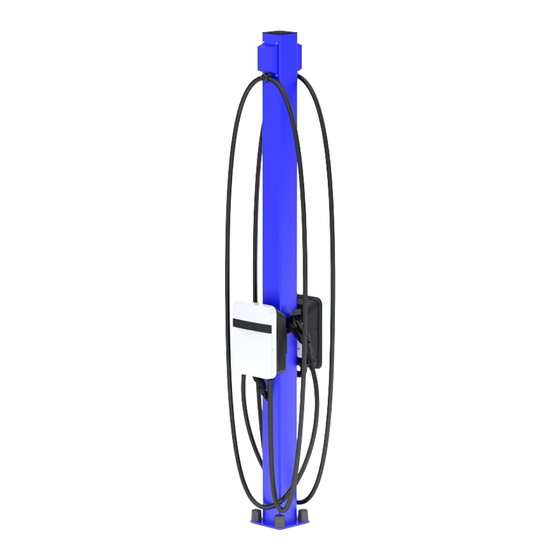
Charging Station Pedestal Installation Manual 1. Intro 1.1. Pedestal Overview 8FT PEDESTAL PEDESTAL Figure 1.1 Pedestal Components Overview... -
Page 5: Box Contents
90° To Conduit Black O-RING BLACK NUT, NYLON, BLACK BLACK Conduit Hand Hole Cover Gasket Hand Hole Cover Ford Blue Hand Hole Cover White Round Nut Covers Black 5" Square Black Plastic Push In Top Cap ½" x 4-¼" Stainless Steel... -
Page 6: Safety Instructions
Charging Station Pedestal Installation Manual 2. Safety Instructions SAVE THESE INSTRUCTIONS Read carefully all documentation before handling the equipment and pay special attention to safety recommendations to maximize the performance of this product and ensure its safe use and installa- tion. -
Page 7: Site Preparation
Charging Station Pedestal Installation Manual 3. Site Preparation 3.1. Site Recommendations When deciding the location of the equipment and planning its installation, it is recommended to follow a series of guidelines derived from its characteristics. NOTE The instructions given in this section must not replace in any way the mandatory regulations of the area in which the equipment will be installed. -
Page 8: Site Basis
Charging Station Pedestal Installation Manual 3.3. Site Basis The manufacturer recommends making a concrete foundation slab to support the charger pedes- tal. The support surface for the equipment must be perfectly level. The client is responsible for the correct dimensioning and construction of the foundation in accordance with current regulations. The foundation must meet the following characteristics: •... -
Page 9: Anchoring The Equipment
Charging Station Pedestal Installation Manual See anchor recommendations at the “Anchoring the Equipment” section. NOTE Each charger must be anchored to a foundation which guarantees its stability to- wards vertical and horizontal actions. It is customer’s responsibility to design and build the foundation to guarantee stability of each equipment. -
Page 10: General Dimensions
Charging Station Pedestal Installation Manual The following image (bottom-up view) shows the location and diameter of the charger´s anchoring holes. They are located at the foot of the pedestal. NOT TO SCALE R.31 .63 in 8.50 in 10.0 6.63 in Conduit Entry Hole 4.25 in FRONT... -
Page 11: Pedestal Installation
Charging Station Pedestal Installation Manual 4. Pedestal Installation 4.1. Unboxing 1. Remove pedestal and accessory kit from box. Remove counterweight cable ties from base (8ft models only). Remove cardboard insert from inside pedestal shaft (8ft models only). 4.2. Base Anchoring 2. -
Page 12: Figure 4.2 Install Anchors
Charging Station Pedestal Installation Manual 3. Drill anchor holes with ½" bit. Install (4X) wedge anchors to a minimum embedment of 2-¼". Place pedestal on anchors. Figure 4.2 Install Anchors 4. Level pedestal. Place (4X) washers and (4X) nuts. Torque nuts to 50-60 ft.-lbs. Install (4X) nut covers. -
Page 13: Charger Installation
Charging Station Pedestal Installation Manual 4.3. Charger Installation 5. Install optional charger holster if provided per Charger Installation Manual with (2X)¼"- 20 x ¾" long screws and (2X) ¼" lock washers (per holster). Torque to 75 in.-lbs. Figure 4.4 Install Charger Holster 6. -
Page 14: Conduit Assembly Installation
Charging Station Pedestal Installation Manual 4.4. Conduit Assembly Installation 8. Install conduit assembly, O-ring and nut. 9. Torque to 35-40 in.-lbs. Follow Charger Installation Manual for input power cord instal- lation. Reinstall charger covers per Charger Installation Instructions. Figure 4.6 Install Conduit Assembly... -
Page 15: Figure 4.7 Install Knock Out Seal
Charging Station Pedestal Installation Manual 10. Install conduit knock out seal to plug hole when a single charger is used. Figure 4.7 Install Knock Out Seal NOTE When mounting only 1 charger, use the accessory kit and follow the included in- structions to close off the remaining post openings. -
Page 16: Retractor Cable Clamp Assembly Installation (For 8Ft Pedestal Only)
Charging Station Pedestal Installation Manual 4.5. Retractor Cable Clamp Assembly Installation (For 8ft Pedestal Only) 11. Install proper cable insert and attach hose clamp half to secure power cable. Fasten with (2X) #8 screws. (8ft models only) 12. Choose insert size based on power cord diameter. Place clamp 8ft down from charger housing. -
Page 17: Plug Remaining Holes
Installation Manual Table 4.1 Cable Clamp Insert Identification Cable Clamp Insert Power Cable Size 23.5mm 22mm 19.4mm 15mm Ford Pro AC Ford Pro AC Ford Pro AC Ford Pro AC Charging Station Charger Model Charging Station Charging Station Charging Station 80A;... -
Page 18: Hand Hole Cover Installation
Charging Station Pedestal Installation Manual 4.7. Hand Hole Cover Installation 14. Install hand hole cover with (4X) #6 flat head screws. Figure 4.10 Install Hand Hole Cover 4.8. Top Cap Installation 15. Install top cap. Figure 4.11 Install Top Cap... - Page 19 Model e Dealer Support The Limited Warranty associated with your product is subject to certain exceptions and exclusions. For the terms of the limited warranty please contact Ford Pro or Model e support. Telephone: US Dealer Support: 866-34-DEALER (866-343-3253)
Need help?
Do you have a question about the PRO FPC-PO0048CZ-UAA and is the answer not in the manual?
Questions and answers