
Related Manuals for Ford NB 240 Series


Summary of Contents for Ford NB 240 Series
- Page 1 DC Charging Station NB 240 series Installation Manual NB 240 series Installation Manual Dealer Support Line 1-866-34-DEALER Customer Support Line US: 1-888-357-1009 or CAN: 1-888-357-1019...
- Page 2 NB 240 series Installation Manual Edition: October 2023 NB240HW02BI Rev. B...
-
Page 3: About This Manual
From now on, this manual refers to Standalone NB 240 series with the term “equipment” or “charger”. Please notice the NB 240 range includes the chargers NB 150 / NB 180 / NB 210 / NB240. - Page 4 DC Charger NB 240 Installation Manual REVISIONS CONTROL DATE (DD/MM/YYYY) REVISION DESCRIPTION First edition. 30 / 06 / 2023 Important safety instructions. Introduction. Handling and transportation. 05 / 10 / 2023 Cable access and connections. Start up procedure. Emergency stop and restart.
- Page 5 DC Charger NB 240 Installation Manual The equipment and technical documentation are periodically updated. The manufacturer reserves the right to modify all or part of the contents of this manual without previous notice. The reproduction or distribution of the present manual is strictly forbidden unless express authorization from the manufacturer.
-
Page 6: Table Of Contents
Advanced charge functionality ......................18 Open door detection ........................... 18 Regulatory framework ......................... 18 2. TECHNICAL CHARACTERISTICS ......................19 Standalone NB 240 series – UL ......................19 3. DIMENSIONS AND WEIGHT ........................20 4. HANDLING AND TRANSPORTATION ....................22 Reception ............................22 Standard storage .......................... - Page 7 DC Charger NB 240 Installation Manual 4G Communication ..........................45 Wi-Fi communication ..........................45 Ethernet communication ........................46 10. LOTO PROCEDURE..........................47 Equipment status ..........................48 LOTO actions .............................49 Check points for absence of voltage....................50 11. START UP PROCEDURE........................52 12. SAFE STOP ............................53 13. EMERGENCY STOP AND RESTART ....................54 14.
-
Page 8: Acronyms
DC Charger NB 240 Installation Manual ACRONYMS The terms commonly used in the documentation are listed in the table below. Please notice this is a general series of terms and it encompasses different product divisions (industrial, solar, storage, and electric mobility), thus, some of the following expressions may not apply to this particular manual. ACRONYM MEANING AASS... - Page 9 DC Charger NB 240 Installation Manual ACRONYM MEANING Residual Current Monitor RFID Radio Frequency Identification State Of Charge – referred to battery State Of Health – referred to battery. It compares the actual state of the battery to its initial condition.
-
Page 10: Safety Symbols
DC Charger NB 240 Installation Manual SAFETY SYMBOLS Always follow safety instructions to prevent accidents and potential hazards from occurring. In this manual, safety messages are classified as follows: Identifies potentially hazardous situations where dangerous voltage may be present, which if not avoided, could result in minor personal injury, serious WARNING injury or death. -
Page 11: Important Safety Instructions
DC Charger NB 240 Installation Manual IMPORTANT SAFETY INSTRUCTIONS SAVE THESE INSTRUCTIONS Read carefully all documentation before handling the equipment and pay special attention to safety recommendations to maximize the performance of this product and ensure its safe use and installation. This document covers the most important and frequent potential causes of damage to equipment or personnel. - Page 12 DC Charger NB 240 Installation Manual WARNING The housing must be properly closed, otherwise it may not adequately protect people or property from any abnormal situation inside the equipment. Always follow the instructions in the manual to move and position the equipment. The weight of this equipment can cause injuries, serious injuries and even death if not handled correctly.
- Page 13 DC Charger NB 240 Installation Manual CAUTION Install the equipment, both the power station and the recharging posts, on a solid, level surface in a location where there is no risk of explosion, flooding, or impact damage. Follow the recommendations on how to build the foundation of this manual. Otherwise, there is a risk of malfunction and even permanent damage.
- Page 14 DC Charger NB 240 Installation Manual PERSONAL PROTECTIVE EQUIPMENT (PPE from now on) REQUIRED The use of PPE in accordance with standards is required to repair and maintain the equipment. Follow applicable instructions at the installation site to comply with national and local regulations. In the case of tasks with voltage present, it is mandatory to use an Electric Arc Safety Kit (gloves, clothing, and face protection).
- Page 15 DC Charger NB 240 Installation Manual The following table shows the protection class type, depending on the working voltage. ELECTRICAL INSULATED GLOVES Class AC (V DC (V 1000 1500 7500 11250 17000 25500 26500 39750 36000 54000 ELECTRICAL SAFETY MATTING Class AC (V DC (V...
- Page 16 DC Charger NB 240 Installation Manual NOTICE CYBERSECURITY DISCLAIMER This product is designed to be connected to and to communicate information and data via a network interface. Access to the system is restricted to those employees who legitimately need it for reasons of maintenance and/or updating of the system.
-
Page 17: Torque And Screw Sizing
DC Charger NB 240 Installation Manual TORQUE AND SCREW SIZING The following table shows, broadly speaking, the recommended torque for both mechanical and electrical [1,2] connections, applicable to all cabinets SCREW SIZE RECOMMENDED TORQUE DIN (Nm) ASTM (ft*lb) METRIC IMPERIAL (mm) (in.) 6.9 QUALITY... -
Page 18: Introduction
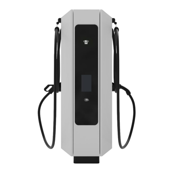
The following sections describe the different components of the EV charger. Charger The NB 240 series is provided with two independent charging cables with connectors for DC charging of electric vehicles with CCS-1 standard for DC. The possible installation and combination of connectors depends on the application of local regulations. -
Page 19: Charging Process
DC Charger NB 240 Installation Manual Connectors The charger has up to two independent charging cables with the standard CCS-1 connectors. The connector brackets are located on each side of the equipment. The following section describes the parts of each connector. CCS-1 connector Locking mechanism... -
Page 20: Advanced Charge Functionality
The power cabinet door must be correctly locked after installation, service, or repair operations. Regulatory framework The NB 240 series are devices that are connected to the AC low-voltage network and provides a DC power supply at a variable voltage of 150 to 1000 V for charging electric vehicles. -
Page 21: Technical Characteristics
DC Charger NB 240 Installation Manual 2. TECHNICAL CHARACTERISTICS Depending on the regulation to be followed, the equipment will fulfill different technical characteristics. Standalone NB 240 series – UL NB150SH / NB180SH / NB210SH / NB240SH / REFERENCE NB150SU NB180SU... -
Page 22: Dimensions And Weight
DC Charger NB 240 Installation Manual 3. DIMENSIONS AND WEIGHT The dimensions, gravity center and the weight of the NB 240 series are detailed in this section. GENERAL DIMENSIONS 2088 2000 33.5 1900 82.20 78.74 1.32 33.46 37.40 37.64 3.94 74.80... - Page 23 609,6 mm (24 in.) and height is less than 1168,4 mm (46 in.) although the manufacturer still recommends the installer to leave proper access to the side of the charger. The approximate weight for the NB 240 series is 580 kg (1279 lb.) . The weight of each charging cable is detailed...
-
Page 24: Handling And Transportation
DC Charger NB 240 Installation Manual 4. HANDLING AND TRANSPORTATION CAUTION Please read the following transport and installation instructions carefully. Failure to follow the transport and installation instructions could result in damage to the equipment or injury to persons. Reception The equipment is delivered packed. -
Page 25: Extended Storage
DC Charger NB 240 Installation Manual Extended storage If the equipment is stored for an extended period of time (6 months or more) before installation, new considerations should be taken in addition to the recommendations in the previous section “Storage”: •... - Page 26 DC Charger NB 240 Installation Manual The equipment fixed on the pallet is ready to be handled by forklift truck and be transported by truck or container. Keep in mind the load distribution and center of gravity. For sea freight, the equipment is packed assembled vertically, in a cardboard box and fixed on a pallet base with screws at four steel brackets.
- Page 27 DC Charger NB 240 Installation Manual The following image shows an example of lifting the equipment with slings: Removal of the lifting tools Once the equipment has been anchored, the lifting tool must be removed by following these steps: Open the two side doors of the equipment Once both doors are open, remove both lifting tools by unscrewing the three M6 screws of each one.
-
Page 28: Preparation For Installing The Equipment
DC Charger NB 240 Installation Manual 5. PREPARATION FOR INSTALLING THE EQUIPMENT Site recommendations When deciding the location of the equipment and planning its installation, it is recommended to follow a series of guidelines derived from its characteristics. CAUTION To guarantee proper electrical installation, it is very important to comply with the bend radius of the cable. - Page 29 DC Charger NB 240 Installation Manual • Soil compaction degree of 98%. • Maximum land unevenness of 0.25%. • It must not be a direct place of passage so that the load cables do not interrupt the movement of pedestrians or traffic. Site basis The manufacturer recommends making a concrete foundation slab to support the charger.
-
Page 30: Minimum Working Distances
DC Charger NB 240 Installation Manual Minimum working distances CAUTION When installing the equipment, keep the minimum safety distances. Be aware of all the minimum insulation requirements established by the applicable electrical code, as well as the thermal, safety and accessibility requirements. -
Page 31: Charging Cable Maneuverability
DC Charger NB 240 Installation Manual NOTICE Depending on the location, installation and environmental condition, distances may change to have adequate ventilation. Charging cable maneuverability To ensure the adequate maneuverability of both charging cables, when installing the equipment, note that the maximum effective charging cable length is A = 4.6 m (15.1 ft) or optionally 7.2 m (23.7 ft). -
Page 32: Anchoring Of The Equipment
DC Charger NB 240 Installation Manual Anchoring of the equipment NOTICE It is the installer’s responsibility to correctly dimension posts anchoring to the foundation, guaranteeing stability towards horizontal actions. The equipment must be anchored to a solid and leveled surface (slab), see slab recommendations at the “Site basis”... -
Page 33: Ventilation System
Noise level The NB240 (and all its power levels) noise level is below 65 dB at 1 meter from the charger and below 60 dB at 3 meters. Consult with Ford for more information. Dealer Support Line 1-866-34-DEALER Customer Support Line US: 1-888-357-1009 or CAN: 1-888-357-1019... -
Page 34: Cable Access And Connections
DC Charger NB 240 Installation Manual 6. CABLE ACCESS AND CONNECTIONS WARNING Before opening any door, the equipment must be completely isolated, without any voltage. Make sure to follow the insulation guidelines and all safety instructions indicated in the "Safety instructions"... -
Page 35: Access
DC Charger NB 240 Installation Manual Access WARNING MODIFICATION WILL VOID WARRANTY Do not modify the equipment in any way. Modification definition includes and is not limited to drilling holes, puncturing equipment, adding, or retrofitting with components etc. If you do so, the manufacturer will not assume any liability and the product warranty will be voided. - Page 36 DC Charger NB 240 Installation Manual Access dimensions are detailed in the figure below (bottom-up view): 237.5 137.5 87.5 11.46 9.25 26.85 9.35 8.86 7.60 5.41 5.20 3.44 1.26 1.26 74.5 145.5 93.5 33.5 153.5 3.23 3.66 5.63 3.68 1.32 1.10 6.04 8.27...
- Page 37 Only the amount of cable glands needed for the project must be used. A blank plate is included to suit individual site needs. Ford always recommends following the holes pattern shown below. If this is not possible, it is customer's responsibility to meet wire bending requirements.
-
Page 38: Connections
DC Charger NB 240 Installation Manual Ethernet access plate The following image shows the footprint view of the standard ethernet cable entry plate. Eth. Note: This plate is used only when ethernet is used as the mode of communication. Connections This section details the input and output connections that must be performed in the equipment. - Page 39 DC Charger NB 240 Installation Manual AC input power connections Cable size: The tables below show the input rated current, as well as the recommended cable size for the NB 240 range equipment. Installer must dimension the wiring taking into consideration the minimum and maximum diameter, as well as the particularities of the project: MINIMUM RECOMENDED INPUT RATED CURRENT...
- Page 40 DC Charger NB 240 Installation Manual The following pictures show the distance from base to power terminals and from ground to the gland plates of the equipment. 101.5 336.5 404.5 3.99 13.25 14.17 15.95 16.73 The following figure shows the correct connection of the neutral (N), ground (PE) and a single power input connection (L1, L2 and L3): REF.
- Page 41 DC Charger NB 240 Installation Manual In case of the double power supply input (L1, L2 and L3), the connections are as follows: REF. ELEMENT Terminal lug Bolt M12 (1/2”) Spring washer Fender washer Plate M12 (1/2”) nut Note: If the terminal is a single-hole terminal, it is recommended to connect it to the upper hole in the busbar, so that the contact area is maximized.
- Page 42 DC Charger NB 240 Installation Manual Communications connection Ford recommends connecting the equipment via 4G as the preferred option, Wi-Fi as the second option and Ethernet as the last option. Ethernet requirements (if needed) • Recommended cable size: Ethernet CAT 5e - RJ45 Connection Switch.
-
Page 43: Protections
DC Charger NB 240 Installation Manual 7. PROTECTIONS This section describes the different protections available to the equipment. Insulation monitoring The equipment has an insulation monitor to detect possible insulation faults in DC charge. Overcurrent and short circuit protection The equipment includes the following protections: Nominal Nominal Breaking... -
Page 44: Interface
DC Charger NB 240 Installation Manual 8. INTERFACE Controls The electric vehicle user interacts with the charger primarily through a touch screen (display). The charger has different forms of authentication: by an optional POS system (Point of Sale), by RFID card or through a mobile application. - Page 45 DC Charger NB 240 Installation Manual • Inside the cabinet, every power module has three LED indicators. Picture illustrates LEDs in the power module when the door is open: NORMAL ABNORMAL DESCRIPTION INDICATOR STATE STATE If ON, it indicates a fault has been triggered in the power module. In that FAULT (red) case, the equipment will run without using this power module.
-
Page 46: Communications
DC Charger NB 240 Installation Manual 9. COMMUNICATIONS The equipment features multiple connectivity options. Each one has its own aim and purpose, described in this section. There are three ways to connect the equipment for remote monitoring and control; 4G (most preferred), Wi-Fi and Ethernet (as least preferred). -
Page 47: Communication
For communication via 4G a MicroSIM card is pre-installed into the indicated charger control card slot: If it is necessary to replace the MicroSIM, consult Ford for further information regarding its configuration. The following table shows the main 4G communication characteristics:... -
Page 48: Ethernet Communication
DC Charger NB 240 Installation Manual Once configured, the user can start a charging session through any of the possible identification methods. Ethernet communication The equipment requires an Ethernet entry connection for OCPP1.6 communications and internet connection. Note that this connection is not necessary if communication is established via 4G, or Wi-Fi, for more information see section "4G Communication". -
Page 49: Loto Procedure
DC Charger NB 240 Installation Manual 10. LOTO PROCEDURE The aim of the lockout / tagout or LOTO procedure is to protect the user towards unintended reconnections and to avoid risks associated with the control of energy sources. This involves isolating, locking, and tagging the dangerous energy sources to avoid accidents / incidents mainly derived from dangerous movements, unexpected energizations, or stored energy discharges. -
Page 50: Equipment Status
DC Charger NB 240 Installation Manual Equipment status Before working with the equipment, it is convenient to define two possible statuses. NB240 SERIES STATUS • Charger energized. • Equipment running (no action required from safe stop). STATUS 1 Check points for absence of voltage: No measuring in Status 1. •... -
Page 51: Loto Actions
LOTO action. Disconnect all charging processes following the safe stop instructions or wait until all charging sessions are finished: For the NB 240 series equipment. Then, limit the access to the charger, so no one can start a new charging process. -
Page 52: Check Points For Absence Of Voltage
DC Charger NB 240 Installation Manual Check points for absence of voltage Follow this procedure after LOTO actions to reach status 2 for the equipment. See previous subsections. CHECK POINTS FOR ABSENCE OF VOLTAGE Wear the appropriate PPE based on the electrical arc studies and the risk assessment carried out by the installer. - Page 53 DC Charger NB 240 Installation Manual Remove LOTO actions CAUTION Auxiliary supply must be disconnected last and connected first when possible. Electric shock hazard. Auxiliary supply power layout is a characteristic of each plant and may vary from one installation to another. Check the latest electrical schematics of the plant and make sure no voltage is present by confirming with a multimeter.
-
Page 54: Start Up Procedure
After installation, please use computer, tablet or mobile device to visit http://tinyurl.com/goDCfast and complete the Start Up Checklist for confirmation of installation, prior to remote commissioning. Contact Ford prior to starting up the equipment for commissioning. Dealer Support Line 1-866-34-DEALER Customer Support Line US: 1-888-357-1009 or CAN: 1-888-357-1019... -
Page 55: Safe Stop
DC Charger NB 240 Installation Manual 12. SAFE STOP CAUTION The shutdown of the equipment must only be carried out by personnel qualified. Read these instructions and all safety recommendations carefully. Otherwise, the equipment could be damaged and seriously injured personnel. -
Page 56: Emergency Stop And Restart
DC Charger NB 240 Installation Manual 13. EMERGENCY STOP AND RESTART The following steps must be taken to activate the emergency stop, and subsequent restart, of the equipment: Press the emergency stop pushbutton, located on the right side of the equipment. Verify that the reason for the hazard or emergency has been resolved. -
Page 57: Maintenance
DC Charger NB 240 Installation Manual 14. MAINTENANCE The NB 240 series have been developed based on a revolutionary design concept that significantly simplifies the tasks and reduces preventive and corrective maintenance times. Nonetheless, there are some actions and revisions required. -
Page 58: Checklist
The list of tasks detailed below should be carried out annually on the equipment. The time of each task is an estimate for NB 240 series equipment. In case of having the optional additional dispenser, the maintenance time will be doubled. -
Page 59: Status 1
DC Charger NB 240 Installation Manual Status 1 1. Environmental condition Verify that the equipment environment complies with the specifications. Verify that the humidity is adequate. CAUTION This task should be carried out annually. However, it should be done more frequently if climate condition require so. -
Page 60: Status 2
DC Charger NB 240 Installation Manual 8. Operation of the differential switch (optional) If the optional differential switch has been requested, check the correct operation of it using the test button enabled for this purpose on the differential itself. Open the unit without voltage, then energize it without any load, carry out the test and finally close the door.
Need help?
Do you have a question about the NB 240 Series and is the answer not in the manual?
Questions and answers