Table of Contents
Advertisement
Quick Links
Advertisement
Table of Contents
Troubleshooting

Related Manuals for Ricoh MP CW2201


Summary of Contents for Ricoh MP CW2201
- Page 1 MP CW2201 Machine Code: D262 Field Service Manual March, 2016...
- Page 3 Important Safety Notices Warnings, Cautions, Notes In this manual, the following important symbols and notations are used. • A Warning indicates a potentially hazardous situation. Failure to obey a Warning could result in death or serious injury. • A Caution indicates a potentially hazardous situation. Failure to obey a Caution could result in minor or moderate injury or damage to the machine or other property.
- Page 4 Switches and Symbols Where symbols are used on or near switches on machines for Europe and other areas, the meaning of each symbol conforms with IEC60417. Safety Prevention of Physical Injury 1. Before disassembling or assembling parts of the machine and peripherals, make sure that the machine and peripheral power cords are unplugged.
- Page 5 16. When using a vacuum cleaner around the machine, keep others away from the cleaner, especially small children. Observance of Electrical Safety Standards 1. The machine and its peripherals must be installed and maintained by a customer service representative who has completed the training course on those models with exceptions on some machines where the installation can be handled by the user.
- Page 6 1. Always store ink cartridges out of the reach of children. 2. Always store ink cartridges in a cool, dry location that is not exposed to direct sunlight. Ink Cartridge Disposal 1. Attach the caps to empty ink containers for temporary storage to avoid accidental spillage. 2.
-
Page 7: Symbols And Trademarks
Symbols and Trademarks Symbols Symbol What it means Bushing C-ring Connector E-ring FFC (Flexible Film Cable) Gear Harness clamp Hex head screw Hook (or tab release) Knob screw (black) Knob screw (sliver) Pivot screw Screw (common screw) Shoulder screw Spring Standoff Stud screw Timing belt... -
Page 8: Trademarks
• The notations "SEF" and "LEF" describe how paper is fed from the bypass tray, short edge first or long edge first. • "Main Scan" means "horizontal direction", the left to right and right to left movement of the carriage. •... -
Page 9: Table Of Contents
Specifications..............................25 Main Machine, Peripherals, Options......................26 Model Numbers and Names........................26 Configuration............................... 27 Guidance for Those Who Are Familiar with Predecessor Products............. 29 Comparison to MP CW2201........................29 Overview................................30 New Features............................... 30 Auto Nozzle Check..........................30 Carriage Unit............................31 Ink Supply Motors..........................32 Carriage LED Lamp.......................... - Page 10 Machine Level.............................. 61 Power Source............................... 61 Installation Overview...........................62 Installation Flow...........................62 Main Machine Installation..........................64 Before You Begin............................64 Accessory Boxes..........................64 What You Need..........................65 Accessory List in Box [3]........................65 Accessory List in Box [5]........................67 Main Unit Stand............................67 Accessories: Main Unit Stand......................67 Installing the Main Unit Stand......................
- Page 11 Original Stacker, Guides..........................115 Installing the Original Stacker, Guides................... 115 Ink Collector Tank Storage Shelf......................117 Installing the Ink Collector Tank Storage Shelf................117 Exit Stacker..............................119 Accessories: Exit Stacker........................119 Installing the Exit Stacker........................119 Changing the mode of the Paper Exit Stacker................125 Ink Filling..............................126 Draining and Filling Procedure......................126 If Draining Fails to Start........................
- Page 12 Overview............................149 Move Exec............................149 Undo Exec............................150 IEEE 802.11 a/g/n Interface Unit Type M19..................151 Included Parts............................152 Installation............................152 Attaching Antennas...........................153 Checking the Wireless LAN Interface Connection.................158 OCR Unit Type M13..........................159 Recovery Procedure......................... 162 File Format Converter Type M23 (MLB)....................163 Included Parts............................163 Installation of MLB..........................
- Page 13 Settings Relevant to the Service Contract....................185 Settings for @Remote Service........................185 3. Preventive Maintenance Preventive Maintenance Tables........................191 PM Cleaning Points............................192 PM Table..............................192 Scanner Unit............................192 Horizontal Unit..........................195 Waste Ink Collection........................199 Other Items for Cleaning.......................... 203 External Covers..........................203 Scanner Unit............................204 Horizontal Unit..........................206 Paper Feed............................
- Page 14 Right Plate Screws..........................222 Maintenance Unit Base Screws.......................223 Solenoid Bracket Screw........................224 Main Carriage Screws........................225 Temperature/Humidity Sensor Bracket..................225 Notes on Operation of the Paper Holding Lever................226 Common Procedures............................. 228 Before You Begin............................228 Before Servicing the Machine........................229 Rear Output Guides..........................229 Original Guides..........................
- Page 15 Before You Begin..........................267 Move the Carriage Unit with SP2-102-4..................267 Uncapping the Print Heads and Moving the Carriage Unit Manually........269 Capping the Print Heads Manually....................273 Disconnecting the Main Unit from the Scanner Unit................274 Disconnecting the Scanner Cable....................275 Separating the Main Unit from the Scanner Unit ................278 Operation Panel............................
- Page 16 Adjustment............................310 White Plate Bracket...........................310 Original Stop Switch..........................311 Roll Units.................................314 Roll Unit 1..............................314 Remove..............................314 Precaution............................320 Roll Unit 2 (Option)........................... 322 Remove..............................322 Precaution............................327 Rewind Switch............................329 Remove..............................329 Precaution............................330 Left Outer Cover, Left Inner Cover......................330 Remove..............................330 Precaution............................331 Encoder Sensors............................332 Remove..............................332 Cleaning............................333 Roll Paper Feed Motor..........................334 Roll Paper Feed Clutch..........................336 Remove..............................336...
- Page 17 Feed Roller..............................355 Remove..............................355 Precaution............................358 Roll End Sensor............................358 Paper Transport..............................361 Bypass Sensor............................361 Pre-Registration Sensor..........................362 Registration End Sensor..........................363 Paper Transport Fan Motor........................364 Paper Exit................................366 Cutter................................366 Exit Guide..............................367 Remove..............................367 Precaution............................368 Cutter Unit..............................369 Cutter Switch (Right)..........................372 Cutter Switch (Left).............................373 Cutter Motor..............................
- Page 18 Sub Scan................................ 393 Vertical Encoder Sensor..........................393 Precaution............................394 Vertical Encoder Wheel, Timing Belt....................... 394 Vertical Encoder HP Sensor........................397 Vertical Motor............................399 Bypass Stopper Clutch Sensor......................... 400 Bypass Stopper Clutch..........................402 Carriage Unit..............................406 Before You Begin............................406 DRESS Sensor............................407 Remove..............................408 Cleaning............................410 Adjustment............................411 LED................................414 Remove..............................414 HRB (Head Relay Board).........................
- Page 19 Ink Tube Rail Removal........................476 Horizontal Encoder Sheet Removal....................477 Tension Bracket Removal......................... 479 Right Plate Removal.......................... 481 Carriage Unit Removal........................486 Precaution............................498 Ink Supply...............................504 Ink Supply Unit............................504 Ink Supply Unit Accessories......................504 Before You Begin..........................505 Ink Supply Unit Replacement......................505 Carriage Disconnection........................506 Ink Supply Unit Removal........................
- Page 20 RFDB (Roll Feeder Drive Board).......................556 Remove..............................556 IOB (Input/Output Board)........................558 Remove..............................558 HDD................................560 Remove..............................560 Settings.............................. 561 BiCU (Base image Control Unit)......................562 Remove..............................563 EEPROM Replacement........................564 NVRAM..............................566 NVRAM on the controller board.....................566 NVRAM (EEPROM) on the BiCU....................568 PSU (Power Supply Unit).......................... 570 Remove..............................571 Precaution............................572 Sensors, Switches............................
- Page 21 Step 9: Scanner Registration......................583 Step 10: Printer: Cut Length......................584 Step 11: Synchro Cut (Trailing Edge Registration)................ 585 CIS Adjustment with SP Modes........................ 586 To Print the CIS Adjustment Pattern....................586 To Adjust the Image at the CIS Joints....................587 To Adjust the Scan Speed Switching....................588 5.
- Page 22 Procedure for Retrieving the Debug Log with SD Card..............626 Reboot/System Setting Reset........................628 System Settings and Copy Setting Reset....................628 System Setting Reset......................... 628 Copier Setting Reset......................... 628 NVRAM Data Upload/Download......................630 Uploading Content of NVRAM to an SD card..................630 Downloading an SD Card to NVRAM....................
- Page 23 Overview..............................650 Card Save:............................650 Procedure..............................650 Error Messages............................653 6. Troubleshooting Service Call Conditions..........................655 SC100: Scanning............................656 SC200: Image Writing..........................661 SC300: Not Used............................679 SC400: Not Used............................680 SC500: Paper Feed, Transport........................681 SC600: Communication..........................690 SC700: Not Used............................706 SC800: Firmware............................707 SC900: Software............................718 Printing Problems............................722 Before You Begin............................722 White Lines, Horizontal Banding......................
- Page 24 Faulty Maintenance Unit, Carriage Unit..................728 Mixed Colors.............................728 Print heads clogged..........................728 Faulty Maintenance Unit........................729 Image Abraded, Paper Torn, Ink Running....................729 Gap Adjustment..........................729 Paper Feed Obstruction........................729 Faulty Carriage Unit......................... 730 Color Density Too Light..........................730 Printer Driver Settings........................730 Part of Image Missing, Text Misaligned....................730 Printer Driver Settings........................731 Faulty Controller..........................
- Page 25 Fuses................................759 Scanner Unit.............................. 759 Operation Panel..........................759 SIB (Scanner I/F Board)........................759 Main Boards (PCB Box)..........................760 Controller Board..........................760 IOB (Input/Output Board).......................762 BiCU (Base image Control Unit)......................764 PSU (Power Supply Unit)......................... 767 Carriage Unit............................. 768 HRB..............................768 7. Detailed Description Overview................................
- Page 26 Related SPs..............................784 Image Processing............................785 Features for Printing...........................785 Image Flow..............................786 Copy Job Image Data Flow......................786 Scan Job Image Data Flow......................787 Print Job Image Data Flow....................... 788 Copy Mode Image Processing........................ 788 Print Mode Image Processing........................789 Copy Resolution: Copy Jobs and Print Jobs.................... 789 Copy Jobs............................790 Print Jobs............................791 Image Troubleshooting..........................
- Page 27 Paper Feed Layout..........................819 Operation Sequence When the First Roll is Set................820 Operation Sequence When the Second Roll is Set............... 822 Cutting................................ 822 Manual Cut............................823 Bypass Feed...............................824 Related SPs..............................826 Ink Supply...............................827 Overview..............................827 Ink Cartridge..............................829 Ink Supply Mechanism..........................831 Controlling Ink Supply to the Sub Tanks....................833 The OCFS System..........................
- Page 28 Maintenance Unit............................854 Overview............................854 Capping/Uncapping........................855 Print Head Cleaning Cycle......................857 Manual Print Head Cleaning and Flushing..................861 Automatic Downtime Cleaning......................862 Automatic Mist Cleaning........................863 Auto-Nozzle Check Module........................864 Overview............................864 Timing for Detection..........................865 Detection............................865 Wiping an Electrode Plate....................... 866 When Ink Deficiency is Detected.....................868 Operating Life...........................
- Page 29 SIB (Scanner I/F Board)...........................888 Controller Board............................889 IOB (Input/Output Board)........................891 HDD................................891 BiCU (Base image Control Unit)......................892 PSU (Power Supply Unit).......................... 893 Option................................ 894 File Format Converter Type M23 (MLB)..................894 Energy Save..............................896 Energy Save Mode........................... 896 Specification.............................. 897...
-
Page 31: Product Information
1. Product Information Specifications See Appendices. for the following information: • General Specifications • Printer Specifications • Scanning Specifications • Option Specifications... -
Page 32: Main Machine, Peripherals, Options
1. Product Information Main Machine, Peripherals, Options Model Numbers and Names Model Number Name D262-17 Ricoh MP CW2201 SP Gestetner MP CW2201 Savin MP CW2201 Lanier MP CW2201 D262-21 Ricoh MP CW2201 SP D262-27 Ricoh MP CW2201 SP MP CW2201 SP... -
Page 33: Configuration
Main Machine, Peripherals, Options Configuration Main Machines and Peripherals Item Machine Code Main Machine and Stand D262 Scanning Unit and Stand Standard Roll Unit Standard Exit Stacker Standard Roll Unit RU6550 D3CR (Option) Other Options Option Slot Data Overwrite Security Type M19 D3BS SD Card Slot 1 OCR Unit Type M13... - Page 34 1. Product Information Option Slot File Format Converter Type M23 D3CX Board A IEEE 802.11 a/g/n Interface Unit Type M19 D3BR Board B NFC Card Reader Type M23 D3DG...
-
Page 35: Guidance For Those Who Are Familiar With Predecessor Products
Predecessor Products Comparison to MP CW2201 The MP CW2201 is a wide-format inkjet printer that incorporates the design of the MP CW2200. Here is a brief summary of the features of the MP CW2201 and MP CW2200. MP CW2201 and MP CW2200 Compared... -
Page 36: Overview
1. Product Information Overview New Features Auto Nozzle Check The auto-nozzle check function detects whether the nozzle drops ink correctly. It checks the change in electrical charge caused by the ink dropped to the electrode plate at constant intervals. If ink is not dropped well but the effect is not so severe, the adjacent nozzles drop larger dots for printing to minimize the effect. -
Page 37: Carriage Unit
Overview Carriage Unit MP CW2201 Color print head has two line nozzle for each color and black print head has four line nozzle. -
Page 38: Ink Supply Motors
1. Product Information MP CW2200 Color print head has one line nozzle for each color and black print head has four line nozzle. Ink Supply Motors Two ink supply motors are added for color print head addition. -
Page 39: Carriage Led Lamp
Overview Carriage LED Lamp An LED on the carriage lights during operation to prevent users from opening the front cover by mistake. New Bypass Feed For bypass feed, the user manually feeds a sheet of paper into the front of the machine until the paper edge contacts the stopper [1]. -
Page 40: Configuration
1. Product Information Configuration Scanner harness falls down from center back of scanner unit into the PCB box. MP CW2200's scanner harness falls down from left back of scanner unit. -
Page 41: Locations Of Major Electrical Components
Overview Locations of Major Electrical Components MP CW2201 MP CW2200... -
Page 42: Smart Operation Panel
1. Product Information Smart Operation Panel Name Name Speaker [Back] key [Login/Logout] key [Check Status] indicator Main power indicator [Check Status] key Data In indicator (facsimile and printer [Energy Saver] key modes) USB slot for digital cameras Extended Feature key (EX3) HDMI slot Extended Feature key (EX2) USB slot for NFC card readers... - Page 43 Overview Tilting the operation panel easily Change the angle freely from 0° to 55° on panel New smart UI and classic UI are ready Smart UI Copy Smart UI Scan Classic UI...
-
Page 44: Roll Paper Setting
Roll Paper Setting Roll Paper Setting Position Roll paper setting position of MP CW2201 changes by 40mm forward and 20mm low compared to MP CW2200. It can be set the roll paper without having to bend over too much. New Paper Spool The levers do not have to be lowered for 2-inch core. -
Page 45: Acronyms And Important Terms
Overview Acronyms and Important Terms Here are some commonly used acronyms and standard terms you should know. • DRESS. Direct Realization Edge Scanning Sensor. The DRESS sensor is mounted on the left, lower edge of the carriage unit. It detects skew correction, performs paper registration and does color registration. -
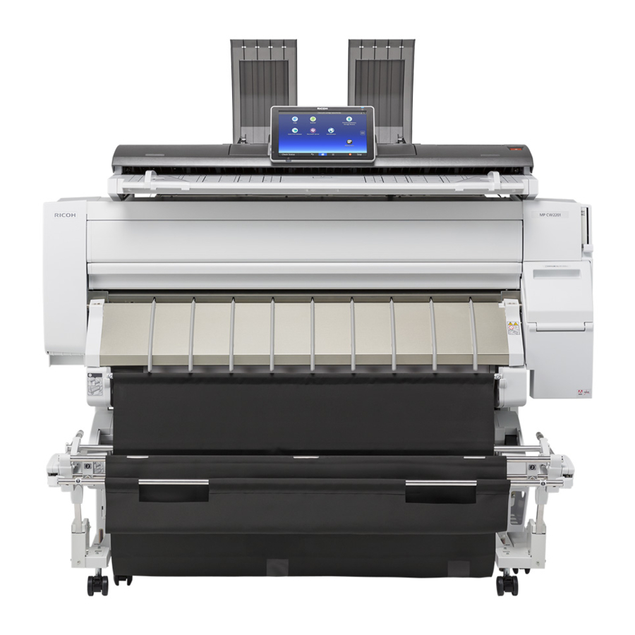
Page 46: Around The Machine
1. Product Information Around the Machine Front 1 Original Stacker 6 Paper Exit Guide 2 Operation Panel 7 Auto-Nozzle Check Unit 3 Scanner Unit Cover 8 Paper Holding Lever 4 Original Table 9 Ink Cartridge Cover 5 Front Cover 10 Exit Stacker Original Tray As each original is scanned, the original guide (1) guides it to the original stacker (2) on top of the machine. - Page 47 Overview Scanner Unit Cover The scanner unit opens easily for removal of paper jams (1), and can be opened to the full vertical position (2) for servicing (this requires disconnect of the arms on the left and right). Original Table The plates on the original table of the scanner unit can be adjusted to accept originals up to 914.4 mm (36 in.) for scanning.
- Page 48 1. Product Information Front Cover The front cover is easily raised and lowered to expose the platen for cleaning and paper jam removal. The front cover locks in place and remains open after it has been raised. Two sensors (micro-switches) on either end of the front cover detect when the cover is opened and closed. When the pin on the left of the front cover is inserted correctly into its track [A], it slides down and pushes a micro-switch [B] to the rear.
- Page 49 Overview Paper Exit Guide The paper exit guide guides printed paper from the machine into the exit stacker attached to the front of the machine. • Two lock magnets on either end of the guide hold it in place when it is open. •...
- Page 50 1. Product Information Paper Holding Lever There is no bypass feed tray, but paper can be fed manually for bypass printing. Raising the paper holding lever [1] lifts the registration rollers [2] so that cut-sheet paper can be loaded on the right side of the platen. Lowering the lever [3] clamps the paper in place for paper feed.
- Page 51 Overview Exit Stacker The exit stacker, attached to the front of the machine, can be adjusted for output: Basket mode and Stack mode • Basket Mode. For standard size paper. The exit stacker is shortened so that it is rounded and deep to hold paper in a small well.
- Page 52 1. Product Information • After configuring the exit stacker for one of these modes, always check the ends of the rods to confirm that they are set correctly. Easy Installation of Exit Stacker The exit stacker is assembled as below at shipping from the factory. Exit stacker installation is easier than MP CW2200.
- Page 53 Overview Optical Cloth Holder Optical Cloth Scanner Stand Ink Collector Tank Cover Ink Collector Tank Left Side The power cord [1], power switch [2], and manual pocket [3] are on the left side of the machine. There is only one power switch on this machine that can cycle the machine off and on.
- Page 54 1. Product Information 1 Power Cord 2 Power Switch 3 Manual Pocket Back Four rear output guides [1] can be attached to the back of the machine to hold originals that exit the back of the machine. The PCB box cover [2] covers the area where the controller board and all other PCBs are mounted on the back of the machine.
- Page 55 Overview 1 Original Output Guides (x4) 2 Rear Cover...
-
Page 56: Main Sections
1. Product Information Main Sections The machine is comprised of five main sections. Scanner. Five staggered CIS units above the original path scan images from the original. • An independent scanner stand supports the scanner. The scanner stand is docked to the back of the main unit and fastened with four screws to the base of the main unit. - Page 57 Overview • Paper is supplied from one roll unit, provided with the main unit. • Suction from one fan below the platen holds the paper in position during feeding and printing. • One additional roll unit can be installed as an option. Printed sheets from both rolls exit the machine at the front.
-
Page 58: Main Components
1. Product Information • The stacker can hold many different sizes of paper. Capacity: 10 sheets. • The printed sheets are stored in the well of the stacker as each exits the machine. Or, the stacker frame can be extended to hold each printed sheet straight after it exits. - Page 59 Overview Item Air release solenoid Maintenance unit Ink supply unit Roll Unit 1 (Std.) Roll Unit 2 (Option) Exit stacker Main unit stand Scanner stand...
-
Page 60: Drive Layout
1. Product Information Drive Layout Item Scanner motor Horizontal motor Bypass clutch Vertical motor... - Page 61 Overview Item Maintenance motor Maintenance lift motor Roll paper feed clutch (Roll Unit 1) Roll paper feed motor (Roll Unit 1) Roll paper feed clutch (Roll Unit 2) Roll paper feed motor (Roll Unit 2) Pre-skew correction clutch 2 (Not-functional) Pre-skew correction clutch 1 (Not-functional) Ink pump motors (seven) Cutter motor...
-
Page 62: Original Path, Paper Paths
1. Product Information Original Path, Paper Paths Item Original path Original width sensors Original set sensor Original registration sensor... - Page 63 Overview Item Original exit sensor Original exit (top) Original exit (rear) Roll paper paths Roll end sensor (Roll Unit 2) Paper entrance sensor (Right, Roll Unit 2) Paper entrance sensor (Center, Roll Unit 2) Exit sensor (Roll Unit 2) Roll end sensor (Roll Unit 1) Paper entrance sensor (Right, Roll Unit 1) Paper entrance sensor (Center, Roll Unit 1) Exit sensor (Roll Unit 1)
- Page 64 1. Product Information...
-
Page 65: Installation
2. Installation Preparation Environment The shaded square in the illustration above is the environment recommended for an office. 1. Temperature Range: 10 °C to 27°C (50 °F to 81°F) 2. Humidity Range: 15% to 80% Rh 3. Ambient Illumination: Less than 1,500 Lux. •... -
Page 66: Minimum Space Requirements
2. Installation • The machine will not be directly exposed to cool air from an air conditioner in the summer. • The machine will not be directly exposed to reflected heat from a space heater in the winter. 7. Do not install the machine in an area filled with gases that can cause corrosion. •... -
Page 67: Configuration
Preparation Configuration Machine Level 1. Front to back: Not more than 5 mm from level 2. Right to left: Not more than 0.15/1000 mm from level. Power Source 1. Input Voltage Level: • North America: 110-120V 3.6 A or more 60 Hz •... -
Page 68: Installation Overview
2. Installation Installation Overview Installation Flow Here is a summary of the sequence recommended for installation of all options. Step Procedure Main Unit Stand Mounting the Main Unit Assembling the Scanner Stand Mounting Scanner Unit Roll Unit 1 (Standard) Roll Unit 2 (Option) Controller Options Connecting Scanner and Main Unit •... - Page 69 Preparation Step Procedure After Installation...
-
Page 70: Main Machine Installation
2. Installation Main Machine Installation Before You Begin • To avoid serious injury or damage to the machine, do not plug the machine into a power source until you are instructed to do so in these installation procedures. Accessory Boxes Content •... -
Page 71: What You Need
Main Machine Installation What You Need Here is a list of tools required for this installation. • Allen key (2.5 mm) One is provided but you may need extra keys if two or more people are working on the installation. •... - Page 72 2. Installation Item Q'ty Drain Cartridge Y Rear Output Guide Original Guide Original Stacker Ferrite Core for LAN Cable Power Cord Optical Cloth Pocket Manual Pocket Rivet (Manual Pocket) Harness Clamp for Roll Unit 1 Harness Clamp for Power Cord Screws M3x8 for Side Pipe Screws M4x8 for Stacker Screws M4x8 for Connecting the Scanner Unit and Main Unit...
-
Page 73: Accessory List In Box [5]
Main Machine Installation Accessory List in Box [5] Item Q'ty Stay for Main Unit Stand Left Support for Main Unit Stand Right Support for Main Unit Stand Left Support for Scanner Stand Right Support for Scanner Stand Center Stay for Scanner Stand Hex Socket Bolt M4x8 Lock washer Allen key... -
Page 74: Installing The Main Unit Stand
2. Installation Item Q'ty 4. Hex Socket Bolt* 4. lock washers 4. Allen key An Allen key is provided for the hex bolts. One lock washer is provided for each socket bolt. Installing the Main Unit Stand • Be sure to attach one lock washer to each hex socket bolt before you fasten the bolt. - Page 75 Main Machine Installation While holding the right support, latch a stay to the rear of the base of the support. Attach the other end of the stay to the rear of the base of the left support so the supports can stand upright by themselves.
-
Page 76: Mounting The Main Unit
2. Installation Push down the front and rear stays to lock them in place. Fasten the front stay [A] and rear stay [B] to the supports ( x4 each). You will need the Allen key to attach the hex socket bolts. Mounting the Main Unit •... - Page 77 Main Machine Installation Item Q'ty - lock washers - Allen key An Allen key is provided for the hex bolts. One lock washer is provided for each socket bolt. • Be sure to attach one lock washer to each hex socket bolt before you fasten the bolt. Locate the vertical positioning pins at the top of both sides of the main unit stand.
- Page 78 2. Installation Locate the handles on the right side of the main unit. Locate the handles on the left side of the main unit.
- Page 79 Main Machine Installation With two people holding the left end [A] and right end [B] (their hands positioned as shown below) lift the main unit and hold it over the top the main unit stand. Position the main unit over the top of the stand so that the triangle marks at the rear are aligned (...
- Page 80 2. Installation With the marks aligned ( ), lower the main unit so that the positioning pins on either end of the stand fit into the holes at the bottom of the main unit frame. Fit each screw with a lock washer. Use an Allen key to fasten the left and right sides of the stand to the bottom of the main unit with the hex-head screws and lock washers ( x3 hex socket bolt)
-
Page 81: Assembling The Scanner Stand
Main Machine Installation Assembling the Scanner Stand Accessories: Scanner Stand Item Q'ty 1. Left Support 2. Right Support 3. Center Stay 4. Hex Socket Bolt M4x8* 4. Lock washer 4. Allen key *1 For the scanner stand assembly and connection of scanner stand to main unit with these bolts, you will need an Allen key. -
Page 82: Installing The Scanner Stand
2. Installation Installing the Scanner Stand • Be sure to attach one lock washer to each hex socket bolt before you fasten the bolt. Position the left and right supports of the scanner stand as shown below. Set the two center stays between the left and right supports. Make sure that the pattern of clustered cutouts [A] are down. - Page 83 Main Machine Installation Engage the ends of the stays on the ends of both stays. Insert the ends of each stay to the left and right supports and tighten by hand ( x16 hex socket bolt). (Do not tighten the hex-head bolts until all have been inserted.) After all the bolts have been inserted and slightly tightened, use the Allen key to tighten all the bolts.
-
Page 84: Mounting The Scanner Unit
2. Installation Set the assembled stand upright. Mounting the Scanner Unit • Mount the main unit immediately after you have removed the box from the pallet and opened the box. • Do not grip the scanner unit by the front end. The front end is made of plastic only and break easily. Parts to be Used Item Q'ty... - Page 85 Main Machine Installation Item Q'ty - Allen key An Allen key is provided for the hex bolts. One lock washer is provided for each socket bolt. • Be sure to attach one lock washer to each hex socket bolt before you fasten the bolt. Locate the vertical positioning pins at the top of both sides of the assembled scanner stand.
- Page 86 2. Installation Arrange the harness [C] in front as shown below. With two people holding both ends of the scanner unit (with their hands positioned as shown below [A] to [D]), set the scanner unit [E] on top of the scanner stand.
-
Page 87: Roll Unit 1 (Standard)
Main Machine Installation Align the cut-outs in the frame of the scanner unit with the positioning pins on either end of the scanner stand. Set the scanner unit on the positioning pins, then fasten the unit to the stand ( x4 hex socket bolt). -
Page 88: Installing Roll Unit 1
2. Installation Item Q'ty Roll Spool with Stoppers Paper Transport Guide Plate (Semi-Transparent) Roll Unit 1 Screw M3x8 with Spring Washer (for Roll Unit) Screw M3x6 (for Paper Transport Guide) Clamp Installing Roll Unit 1 Raise the paper exit guide [A]. - Page 89 Main Machine Installation Locate the positioning pins on the left [A] and right [B] ends of the roll unit. Locate the cut-outs in the left and right supports of the main unit stand. To install the roll unit 1, place the harness backward. •...
- Page 90 2. Installation While holding the unit with both hands: • Set the positioning pins on the left and right ends of the roll unit into the cut-outs in the supports • Push the roll unit in. • Slide it slightly to the right to lock the unit in place.
- Page 91 Main Machine Installation Behind the stand on both sides, make sure that the holes of the roll unit and the stand frame are aligned. Insert the tip of a long screwdriver (30 cm: 12 in.) through each pair of holes to make sure that they are aligned.
- Page 92 2. Installation While holding the paper transport guide with both hands as shown below, insert the pegs on either end of the guide into the cut-outs in the stand on the left [A] and right [B]. The guide should slide into position and fit tightly after correct alignment. •...
- Page 93 Main Machine Installation Fasten the guide to the frame on the right [C] and left [D] ( x2 M3x6). Use a thin edge (like the end of a metal scale) to push the tongues of the guide film sheet up and behind the plate. There are six film sheet tongues. •...
-
Page 94: Wiring Roll Unit 1
2. Installation Attach the clamps, route the harness, and then close the clamps ( x2). Wiring Roll Unit 1 Connect Roll Unit 1 to the machine. The figure below shows the wiring example. IOB CN254 Harness bracket of Roll Unit 1... - Page 95 Main Machine Installation Remove screws on the left cover of the rear of the machine ( x3). Remove the screws circled in red ( x3). Loosen (do not remove) the screws indicated by the red arrows ( x10).
- Page 96 2. Installation Slide the cover to the right and remove it. Attach the harness bracket [A] ( x2 M3x6).
-
Page 97: Roll Unit 2 (Option)
Main Machine Installation Connect the connector of the harness of Roll Unit 1 to IOB [A], and then clamp it ( x1). Check that the clamps beneath the machine are closed and the harness is connected securely. • The harnesses must be flat against the bottom of the PCB box to prevent them from interfering with paper in the bypass feed path. -
Page 98: Accessories
2. Installation Accessories Item Q'ty 1 Roll Unit 2 2 Roll Spool with Stoppers 3 Paper Transport Guide Plate 4 Harness 5 Screw M3x10 with Spring Washer 6 Screw M3x6 7 RFDB 8 Clamp • Remove the protection sheet [A] from the paper transport guide plate. -
Page 99: Installing Roll Unit 2
Main Machine Installation Installing Roll Unit 2 Unpack the roll unit. Locate the positioning pins on the left [A] and right [B] ends. Locate the cut-outs in the left and right supports of the main unit stand. To install the roll unit 2, place the harness backward. •... - Page 100 2. Installation While holding the unit with both hands: • Set the positioning pins on the left and right end of the roll unit into the cut-outs in the supports • Push the roll unit in. • Slide it slightly to the right to lock the unit in place.
- Page 101 Main Machine Installation Insert a long screwdriver (30 cm: 12 in.) into each pair of holes to make sure that they are aligned. Fasten the roll unit to the stand ( x4 M3x8 with washer). Be sure to use the screws with the washers attached.
-
Page 102: Wiring Roll Unit 2
2. Installation Wiring Roll Unit 2 Connect Roll Unit 2 to the machine. The figure below shows the wiring example. IOB CN254 Harness bracket of Roll Unit 1 Harness bracket of Roll Unit 2 RFDB CN301 RFDB CN300 IOB CN255 Remove the screws on the left cover of the rear of the machine ( x3). - Page 103 Main Machine Installation Loosen (do not remove) the screws indicated by the arrows ( x10). Slide the cover to the right and remove it.
- Page 104 2. Installation Attach the RFBD ( x2). Remove the harness bracket [A] ( x2). • Keep the removed screws. They are to be used in the next step. • The removed harness will not be used anymore.
- Page 105 Main Machine Installation Attach the harness bracket of Roll Unit 2 [A] with the screws removed in the previous step x2). Connect the connector of the harness of Roll Unit 2 to RFDB [A] ( x1).
- Page 106 2. Installation Connect the connectors of the harness to RFDB [A] and IOB [B]. Clamp the harness connected in Step 8 and Step 9. Wiring of Roll Unit 2 is completed.
- Page 107 Main Machine Installation Behind the machine, hold the guide plate as shown below, and then set the cut-outs on the left and right over the pegs. Lift the guide slightly, and then insert the bottom pegs into the cut-outs at the lower left and lower right corners.
- Page 108 2. Installation Check each corner of the plate to be sure that each peg is tight in its cut-out. Fasten the plate (tapping x2 - M3x6). Make sure that the clamps are closed and that there is absolutely no slack in the harnesses.
-
Page 109: Controller Options
Main Machine Installation • During bypass feed, the trailing edge of the paper will come out from the back of the machine, and then reverse feed back into the machine. Controller Options If you intend to install one or more of the following options which require the installation of boards, do so before you re-attach the rear cover. -
Page 110: Connecting The Harnesses
2. Installation Connecting the Harnesses At the rear, attach a joint bracket to each side [A] [B] of the stand ( x4 M4x8). Bring the scanner unit and main unit close together. • Dock the left side of the scanner unit to the back of the main unit. •... - Page 111 Main Machine Installation Fasten the scanner stand to the main-unit bracket on the left [A] and right [B] ( M4x8). Connected Machine Rear: Front:...
-
Page 112: Wiring The Scanner Cable
2. Installation Wiring the Scanner Cable Connect the scanner cable of the scanner unit to the machine. The figure below shows the wiring example. IOB CN258 IOB CN259 IOB CN256 IOB CN257... - Page 113 Main Machine Installation BICU CN216 BICU CN215 Ground Clamp Place the scanner unit [A] and main unit [B] as shown below. • The scanner unit is top heavy and unstable. It can fall over easily. Grip the supports below the scanner unit and push it slowly when you move it.
- Page 114 2. Installation Remove the ground plate ( x1 - M3x8). Connect the connectors of the scanner cable [A], [B], [C], and [D] to the IOB.
- Page 115 Main Machine Installation Connect the USB cable [F] and connector [E] to BiCU. Attach the ground clamp to the shielded cable [A] and fasten it to the machine with the screw ( x1 - M3x8).
- Page 116 2. Installation When wiring ends, clamp the scanner cable ( x5). Slide the cover onto the back to re-attach the cover. Make sure all the attached screws are tight in their cut-outs. Re-attach the removed screws circled in red ( x3).
-
Page 117: Clamping The Power Cord
Main Machine Installation Tighten the screws indicated by the arrows ( x10). Fasten the removed screws on the left of the machine ( x3). Clamping the Power Cord Make sure that the power cord is not connected to the power source. Attach the medium-size clamp, connect the power cord [A], and then close the clamp ( x3). - Page 118 2. Installation Remove the filament tape. Connect the ground harnesses of the scanner unit to the back of the machine ( M3x6). • Be sure to connect the ground harnesses securely. Otherwise the normal image may not be obtained on copying or scanning.
-
Page 119: Removing Tapes And Shipping Materials
Main Machine Installation Removing Tapes and Shipping Materials Open the scanner unit and remove the vinyl and filament tape. Remove all the external tape and other materials attached to the machine. Lift the front cover, and remove the filament tape. - Page 120 2. Installation Fold the bottom of the cover into the machine so that it locks and remains open. Remove the tape and other materials attached to the inside of the machine. Remove the tape [A], tape [B], film sheet [C], tape [D], and GAP protective material [E] in this order. •...
-
Page 121: Original Stacker, Guides
Main Machine Installation Close the front cover. Push it in and make sure that it locks. Original Stacker, Guides Installing the Original Stacker, Guides Insert the hooks on the bottom of the original stacker [A] into the holes. Push down the four tabs [B] to attach. - Page 122 2. Installation Attach the original guides [A] to the back of the stacker. Attach the four rear guides [A]. • There are six connection slots for the guides. However, attach the guides to the inner four points (leave both outer slots empty). Use the rivets to attach the manual pocket [A] to the right side of the main unit stand ( x2).
-
Page 123: Ink Collector Tank Storage Shelf
Main Machine Installation Attach the optical cloth pocket at the location shown below. • First, dampen a clean cloth with a small amount of water or alcohol, and then wipe the surface where the optical cloth pocket will be attached. •... - Page 124 2. Installation Fasten the shelf [A] to the stay ( x2 M4x8). Set the extra ink collector tank [B] on the shelf. • When the ink collector tank becomes full, the machine will stop. • The operator can remove the full tank and replace it with the empty tank. •...
-
Page 125: Exit Stacker
Main Machine Installation Exit Stacker Accessories: Exit Stacker Item Q'ty Stacker Assembly Guide: Rod: Lower (Guide Rod) Pipe: Stacker: Side: Front Rod: Stacker: Middle: Assembly Tapping Hexagonal Screws: 3x8 Tapping Hexagonal Screws: 4x8 Installing the Exit Stacker • To fasten the screws of the exit stacker, a stubby is necessary. - Page 126 2. Installation Raise the paper exit guide [A]. If the bolt is protruding from the main unit stand, turn it clockwise until flush. Attach the guide rod to the right foot of the main unit stand. ( x1 M4x8)
- Page 127 Main Machine Installation Attach the guide rod to the left foot of the main unit stand. ( x1 M4x8)
- Page 128 2. Installation Attach the paper exit stacker [A] to the feet of the main unit stand. ( x4 M4x8)
- Page 129 Main Machine Installation Pass the side pipes through the sliders on both sides of the stacker then attach them to the connector block. ( x2 M3x8) • Be sure to insert the pipe fully into the connector block. Otherwise other parts cannot be attached.
- Page 130 2. Installation Attach the rods [A] and [B] to the slots of the guide rods, as shown below.
-
Page 131: Changing The Mode Of The Paper Exit Stacker
Main Machine Installation Pass the middle rod [A] rear of the sheet and insert it into the left and right holes. Attached Paper Exit Stacker Changing the mode of the Paper Exit Stacker The mode of the paper exit stacker can changed according to the purpose. •... -
Page 132: Ink Filling
2. Installation Ink Filling Before a machine leaves the factory, the ink supply tubes, sub tanks, and print heads are filled with priming fluid. This fluid prevents the seams of the joints and connections of the ink supply system from drying out during shipping and storage. - Page 133 Main Machine Installation Turn the power ON. Wait for the machine to beep twice. Enter the SP mode and select SP2-012-001 (Initial Operation Setting). Make sure that it is set to "9". • SP2-012-001 • This SP code is used to modify the initial ink filling sequence at installation and after one •...
- Page 134 2. Installation • To check for completion of an operation with SP, specify SP2-030-001 (Extract Filling Liq Prog Mng: Completed State Flag). If the operation is completed, "00011111" will be displayed for that SP. • If the draining operation does not start, go to the next section below for more about an alternative procedure.
-
Page 135: If Draining Fails To Start
Main Machine Installation • This SP code is used to modify the initial ink filling sequence at installation and after one or more print heads have been replaced. Every time the machine is turned on, the machine checks the ink level in each sub tank. If ink is low, then the machine switches on the ink pump motor(s) to fill the tank(s). -
Page 136: Setting Roll Paper
2. Installation • The ink and primer fluid drain from the tubes, ink sub tanks and the print heads into the ink collector tank. 6. After the operation is completed, flush all the print heads three times. ([User Tools> Maintenance> Flush Print Heads>... - Page 137 Main Machine Installation Remove both the right flange and spool from the paper roll. Insert a spooling flange to touch the paper roll from the right of it. • When loading the paper roll to the paper spool and machine, make sure that the edge of the paper feeds from top of the roll toward the front.
-
Page 138: Setting The Paper Roll To The Machine
2. Installation Insert the spool into the left flange. Lower the lock lever of the left flange to lock the flange. Setting the Paper Roll to the Machine • Be sure to turn the power ON. • Make sure that the output basket is set to standard mode before setting. Lift up the paper input location cover [A] until it clicks. - Page 139 Main Machine Installation Remove bar [A], and then hook it in front of the output basket. If the roll unit 2 is attached, pull down the exit stacker rod [A] attached to the front of the roll unit 2 toward you. Hold both flanges and place the paper roll on the paper input location.
- Page 140 2. Installation Hold the paper roll beneath and feed the paper edge into the guides behind the paper roll. When set correctly, the paper is pulled into the machine and the beeper sounds. Return the bar [B] of the output basket. Push bar [A] into the machine, and then lift bar up and hook it.
-
Page 141: Connecting To The Gigabit Ethernet Interface
Main Machine Installation Make sure that the size of paper roll you loaded is displayed correctly on the screen. • When [Film (Matte)] is specified for Paper Type or when Prevent Paper Abrasion is specified, touch [Exit] on the screen after lowering the paper input location cover. You can change the Prevent Paper Abrasion setting in System Settings if necessary. - Page 142 2. Installation Unshielded Twisted Pair Cable (UTP) or Shielded Twisted Pair Cable (STP) and Category type 5 or more • When using 1000BASE-T: Unshielded Twisted Pair Cable (UTP) or Shielded Twisted Pair Cable (STP) and Category type 5e or more Make loops 3 cm (1.2 inch) [A] from the end of each Ethernet cable and attach included ferrite cores to each loop as shown.
-
Page 143: Check Printing
Main Machine Installation Turn on the main power switch of the machine. Indicator (green) When 10BASE-T is operating, the LED is lit green. Indicator (orange) When 100BASE-TX is operating, the LED is lit orange. Indicators (both orange and green) When 1000BASE-T is operating, both LEDs are lit. •... - Page 144 2. Installation Select the paper feed location and touch [OK]. Follow the prompts to start printing the pattern. Use a loupe or magnifying glass to check the condition of the pattern. • If the pattern shows no broken lines, the machine is ready for operation. •...
-
Page 145: When An Unbroken Nozzle Check Pattern Cannot Be Produced
Main Machine Installation • Never execute print head flushing until you have executed print head cleaning at least 3 times. Touch [Flush Print-heads]. Follow the prompts to complete print head flushing. Print another Nozzle Check Pattern. • If the patterns have no broken lines, you have finished. •... -
Page 146: Final Adjustments
2. Installation On the Printer Features screen, under the List/Test Prints tab, touch [Color Sample]. The color sample prints about 240 palette samples. This is a very large sample and may require a minute or so to finish printing. Check several of the sample blocks. •... -
Page 147: Level Adjustment
Main Machine Installation Level Adjustment Adjust the level of the machine if it is on an uneven surface. Place a leveling mount under the bolt at each corner of the machine. Turn each bolt to lower it onto the leveling mount until it is tight. Open the front cover. -
Page 148: Manual Adjust Head Position
2. Installation Place a leveling instrument on the cross-piece in front of the platen. Use a wrench to adjust the height of each bolt to level the machine. • Make sure that the machine angle is not more than 0.15/1000 mm from level. Manual Adjust Head Position Touch [Home] at the bottom of the screen in the center. - Page 149 Main Machine Installation Select the target location and resolution, and then touch [Start Printing]. Target Location (Paper Source) Paper Bypass Location Bypass paper feed Paper Input Location 1 Roll Unit 1 Paper Input Location 2 Roll Unit 2 Print Quality Speed Priority Draft (pattern A - G) Stan.
-
Page 150: Adjust Paper Feed
2. Installation • The number above the square is the adjustment value. • If you cannot determine the adjustment value, select the square that is between the straightest vertical lines. • Write down these values (A4, B2, etc.) for use later in the procedure. When printing is completed, touch [Adjustment]. -
Page 151: Adjust Print Position
Main Machine Installation When you are prompted, touch [Start Printing]. The adjustment value appears to the left of the lightest gray square with straight horizontal lines on both sides. Touch [Adjustment]. Enter the adjustment values, and then touch [OK]. • Touch [ ] and [ ] to enter the adjustment value of "Top Margin". -
Page 152: Final Settings
2. Installation Select [Print Test Sheet] for the paper feed source. Paper Bypass Location Bypass paper feed Paper Input Location 1 Roll Unit 1 Paper Input Location 2 Roll Unit 2 When you are prompted, touch [Start Printing]. The black arrow indicates the direction of paper feed. Rotate the test sheet 180 degrees. -
Page 153: After Installation
Main Machine Installation After Installation Do these tasks after installation is completed. 1. Perform the SMC List Card Save (SP Text Mode) function to save the SMC list as CSV files to the SD-card inserted into the operation panel SD-card slot. (p.636) 2. -
Page 154: Controller Options
2. Installation Controller Options Overview Slots There are three slots for boards (A, B) and two SD card slots (1, 2) for SD cards on the faceplate of the controller box. Each board or SD card must be inserted into its assigned slot. The slot assignments of boards and SD cards are written on a decal on the controller box cover as shown below. -
Page 155: Standard Controller Features
Controller Options Standard Controller Features • Option SD cards must go into slot 1. If more than one card is used, the modules must be merged onto one SD card. • The Network function, USB Host Function are built in and enabled before the machine leaves the factory. -
Page 156: Undo Exec
2. Installation Remove the SD card slot cover [A] ( x2). Make sure that a target SD card is in SD Card Slot 1 (upper). The application program is moved to this SD card. Insert the source SD card with the application program in SD Card Slot 2 (lower). The application program is copied from this source SD card. -
Page 157: Ieee 802.11 A/G/N Interface Unit Type M19
Controller Options • Do not turn ON the write protect switch of the system SD card or application SD card on the machine. If the write protect switch is ON, a download error (e.g. Error Code 44) occurs during a firmware upgrade or application merge. -
Page 158: Included Parts
2. Installation Included Parts Item Q'ty IEEE 802.11 a/g/n Interface Unit Type M19 Hook and loop fastener Patch Cable Sticker Caution Sheet Caution Sheet Installation • Set the main power switch to OFF and disconnect the power plug from the power outlet before performing the procedure below. -
Page 159: Attaching Antennas
Controller Options Insert the wireless LAN board [B] into Slot A ( x2). • Insert the board fully to the back to connect it firmly. • The removed cover will not be used. The customer should keep it. Attaching Antennas •... - Page 160 2. Installation Use a damp cloth to clean the area [B] on the rear cover. • Hook and loop fastener patches and clamps are to be attached to area [B] to clamp the antenna cables. To avoid Hook and loop fastener patches and clamps being removed, clean the area.
- Page 161 Controller Options Attach the Hook and loop fastener patch at the upper part of the PCB box [2]. Peel the tape from the back of the other Hook and loop fastener patch [1]. Attach the Hook and loop fastener patch at the lower part of the PCB box [2].
- Page 162 2. Installation Attach the antenna 1 to the upper patch. Attach the antenna 2 to the lower patch.
- Page 163 Controller Options Attach a clamp between Antennas 1 and 2 and clamp the antenna cables ( x1). Attach a clamp below Antenna 2 and clamp the antenna cable ( x1).
-
Page 164: Checking The Wireless Lan Interface Connection
2. Installation Open the clamp attached in Step 9 and clamp Antenna cable ( x1). Attach a clamp as shown and clamp the antenna cable ( x1). Output the system setup list and check that the system configuration recognizes the option correctly. -
Page 165: Ocr Unit Type M13
Controller Options 5. Touch [Exit]. Flow of the Setup • For details, refer to the user guide. • If the wireless LAN board does not function correctly, refer to the slip included in the option box. OCR Unit Type M13 Turn OFF the main power. - Page 166 2. Installation Remove the SD card slot cover [A]. ( × 1) Insert the SD card into SD slot 1 or 2 with its label facing [A] the rear of the machine. Turn ON the main power. Touch [EXECUTE] in SP5-878-004 (Option Setup: OCR Dictionary). The SD card ID is saved in the NVRAM, and the ID of the MFP is saved on the SD card.
- Page 167 Controller Options 1. Check whether it is a used SD card. 2. Turn the main power OFF, and repeat steps 1-5. Turn the main power OFF/ON. Press [EXECUTE] in SP5-878-004 (Option Setup: OCR Dictionary). Dictionary data is copied to the HDD. •...
-
Page 168: Recovery Procedure
2. Installation • After installation, the OCR setting can be changed on the "OCR setting" screen. • When setting OCR, set [OCR setting] to [Yes]. (Default setting: [No]) Recovery Procedure When this option is installed, a function is saved on the HDD, and ID information on the SD card is saved in the NVRAM. -
Page 169: File Format Converter Type M23 (Mlb)
Controller Options File Format Converter Type M23 (MLB) Included Parts Item Q'ty Screws Installation of MLB • Set the main power switch to OFF and disconnect the power plug from the power outlet before performing the procedure below. Working with power supplied may cause electrical shock or defects. - Page 170 2. Installation Remove the cover for Slot B [A] ( x2). Attach the cover [B] to the MLB [A] ( x2). Insert the MLB with the cover attached to Slot A. Tighten the screws ( x2). Connect the power plug to a wall outlet and set the main power switch to ON. Output the system setup list and check that the system configuration recognizes the option correctly.
-
Page 171: Data Overwrite Security Unit Type M19
Controller Options Data Overwrite Security Unit Type M19 Overview This option should be installed only for the customer who requires the CC certified Data Overwrite Security function. The function of this option is completely the same as the Data Overwrite Security in Security Functions, which is standard on this machine. -
Page 172: Seal Check And Removal
2. Installation Seal Check and Removal • You must check the box seals to make sure that they are not removed after the items have been sealed in the box at the factory before you do the installation. Check the box seals [A] on each corner of the box. •... - Page 173 Controller Options Remove the SD card slot cover [A]. ( × 1) Insert the SD card (Data Overwrite Security Unit) in SD slot 1 (upper) [A] with its label face towards the front of the machine. Then push it slowly into SD slot 1 (upper) until you hear a click.
-
Page 174: R/W Nfc Personal Authentication Ic Card
2. Installation • SP5-878-001 • Enables the Data Overwrite Security unit. Touch [EXECUTE] on the operation panel. Then cycle the machine off/on. • SP5-801-014 • Initializes the DCS (Delivery Control Service) settings. • SP5-832-001 • HDD Formatting (All) • SP5-832-002 •... -
Page 175: Installation Guide
Controller Options Item Q7ty Plastic screw Ferrite core Decal: Card reader Fastener: R/W Installation Guide • Set the main power switch to OFF and disconnect the power plug from the power outlet before performing the procedure below. Working with power supplied may cause electrical shock or defects. - Page 176 2. Installation Push the operation cover in the direction indicated by the arrows and remove it. • Move the hooks on the rear of the operation cover [A] to the wide end of the mounting holes, and pull up the cover to remove.
- Page 177 Controller Options Fixing the IC card Thread the two mounting holes with the metal screw [A]. Fix the IC card [A] to the plastic plate [B] using the fastener [C]. Fix the plastic plate to the cover ( x2).
- Page 178 2. Installation Screws on the right bracket of the operation panel ( x2). Right cover [A] of the operation panel. Center part of the removed cover. Attach the ferrite core [A] to the USB cable.
- Page 179 Controller Options Loop the cable around the core once. Connect the USB connector [A] to the IC card. Secure the cable with the clamp [A] and dress it as shown.
- Page 180 2. Installation Align the hooks on the rear of the operation cover with the wide end of the mounting holes and pull the cover toward you ( x2). Hook the rear of the operation cover. ( Tighten the screws ( x2).
-
Page 181: Check All Connections
Controller Options Attach the right cover [A]. Attach the right bracket to the operation panel and secure it with screws ( x2). Check All Connections Plug in the power cord. Then turn ON the main power. Enter the printer user mode. Then print the configuration page. User Tools Machine Features Printer Features... -
Page 182: Security Setting
2. Installation Security Setting Security Function Installation The machine contains the Security functions (Data Overwrite Security and HDD Encryption unit) in the controller board. If you are installing a new machine, it is recommended to activate the Data Overwrite Security and HDD Encryption by selecting "Format All Data"... -
Page 183: Data Overwrite Security
Security Setting Data Overwrite Security Before You Begin the Procedure Make sure that the following settings (1) to (3) are not at their factory default values. (1) Supervisor login password (2) Administrator login name (3) Administrator login password If any of these settings is at a factory default value, tell the customer these settings must be changed before you do the installation procedure. - Page 184 2. Installation Press [Auto Erase Memory Setting]. Press [On]. Select the method of overwriting. If you select [NSA] or [DoD], proceed to step 10. If you select [Random Numbers], proceed to step 12. Press [Change]. Enter the number of times that you want to overwrite using the number keys, and then press [#].
-
Page 185: Hdd Encryption
Security Setting Icon [1] This icon is lit when there is temporary data to be overwritten, and blinks during overwriting. Icon [2] This icon is lit when there is no temporary data to be overwritten. HDD Encryption Before You Begin the Procedure: Make sure that the following settings (1) to (3) are not at the factory default settings. - Page 186 2. Installation • When setting up encryption, specify whether to start encryption after deleting data (initialize) or encrypt and retain existing data. If data is retained, it may take some time to encrypt it. Turn ON the main power. Log in as the machine administrator from the control panel. Press [User Tools].
- Page 187 Security Setting Select the data to be carried over to the HDD and not be reset. To carry all of the data over to the HDD, select [All Data]. To carry over only the machine settings data, select [File System Data Only]. To reset all of the data, select [Format All Data].
-
Page 188: Backing Up The Encryption Key
2. Installation Backing Up the Encryption Key The encryption key can be backed up. Select whether to save it to an SD card or to print it. • The encryption key is required for data recovery if the machine malfunctions. Be sure to store the encryption key safely for retrieving backup data. - Page 189 Security Setting The following message appears after the controller board is replaced. In such a case, it is necessary to restore the encryption key to the new controller board. To do this, follow the procedure below. Prepare an SD card that has been initialized in FAT16 format. Using a PC, create a folder in the SD card and name it "restore_key".
- Page 190 2. Installation • User settings will be cleared. Prepare an SD card. Create a directory named “restore_key” inside the root directory of the SD card. Then, save the “nvram_key.txt” file using the following name: /restore_key/nvram_key.txt Create a text file and write "nvclear". •...
-
Page 191: Remote Setting
@Remote Setting @Remote Setting Settings Relevant to the Service Contract Change the necessary settings for the following SP modes if the customer has entered a service contract. • You must select one of the counter methods (developments/prints) in accordance with the contract (SP5-045-001). - Page 192 2. Installation The following settings must be correctly programmed. • Proxy server IP address (SP5-816-063) • Proxy server Port number (SP5-816-064) • Proxy User ID (SP5-816-065) • Proxy Password (SP5-816-066) Get a Request Number. Execute the @Remote Settings Enter the SP mode. Input the Request number which you have obtained from @Remote Center GUI, and then enter [OK] with SP5-816-202 (Remote Service: Letter Number).
- Page 193 @Remote Setting Check the registration result with SP5-816-207 (Remote Service: Register Result). Value Meaning Solution/ Workaround Succeeded Request number error Check the request number again. Already registered Check the registration status. Communication error (proxy Check the network condition. enabled) Communication error (proxy Check the network condition.
- Page 194 2. Installation SP5-816-208 Error Codes Cause Code Meaning Solution/ Workaround Obtain a Request Number Inquiry, registration attempted -12002 before attempting the Inquiry or without acquiring Request No. Registration. -12003 Attempted registration without Perform Confirmation before execution of a confirmation and no attempting the Registration.
- Page 195 @Remote Setting Cause Code Meaning Solution/ Workaround -2385 Other error -2387 Not supported at the Service Center -2389 Database out of service -2390 Program out of service Two registrations for the same Check the registration -2391 mainframe condition of the mainframe Error Caused by -2392 Parameter error Response from...
- Page 196 2. Installation...
-
Page 197: Preventive Maintenance
3. Preventive Maintenance Preventive Maintenance Tables See “Appendices” for the following information: • Preventive Maintenance Tables... -
Page 198: Pm Cleaning Points
3. Preventive Maintenance PM Cleaning Points PM Table The following points are referenced by number in the PM table. Scanner Unit Exposure Glass • Optical glass cleaner cloth, water damp cloth. 1. Raise the scanner unit. 2. Clean the surface of the glass. Original Width Sensors, Original Set Sensor •... - Page 199 PM Cleaning Points 3. Remove the original width sensor cover plate ( x2) (p.285 ) . 4. Clean each sensor with the blower brush. Original Feed Roller • Alcohol, damp cloth, dry cloth 1. Remove the registration sensor cover plate ( x2) (p.289).
- Page 200 3. Preventive Maintenance Original Exit Roller • Alcohol, damp cloth, dry cloth. 1. Remove the top of the scanner unit (p.254). 2. On the left side of the machine, turn the drive gear [A] as you wipe the surface of the roller [B] with the cloth.
-
Page 201: Horizontal Unit
PM Cleaning Points CIS Lens • Lens paper, or clean cloth dampened with alcohol. 1. Raise the scanner unit. 2. Clean the surfaces of the 5 lenses. Horizontal Unit Black Print Head Unit The black print head units can be replaced separately or together (p.425). Color Print Head Unit The black print head units can be replaced separately or together (p.425). - Page 202 3. Preventive Maintenance • Never touch or handle the surface of the encoder strip with bare hands. Smudges and fingerprints can interfere with the sensor readings of the encoder strip. 1. Move the carriage unit to the center (p.267). 2. Remove the top cover (p.245). 3.
- Page 203 PM Cleaning Points 6. Prepare a piece of clean linen cloth dampened with alcohol. 7. Wipe both sides of the encoder strip with the cloth. 8. Clean the strip as far as the carriage on the right, move the carriage to the left, and then clean the other end of the strip.
- Page 204 3. Preventive Maintenance Maintenance Unit • Dry linen cloth. • After replacing the ink collector unit, always remove ink that has hardened around the wiper blade, suction cap, and three print head caps. 1. Move the carriage unit to the center (p.267). 2.
-
Page 205: Waste Ink Collection
PM Cleaning Points Waste Ink Collection Ink Collector Tank 1. Open the ink collector cover on the right side of the machine. 2. Depress the release [A], and then pull the tank straight out of the machine. 3. Lay the tank on a flat surface with the port [B] facing up. •... - Page 206 3. Preventive Maintenance 4. Cover the top of the tank with some paper and tape, and then discard it. • Follow the local laws and regulations regarding the disposal of this item. • Never attempt to empty the right ink sump and re-use it. 5.
- Page 207 PM Cleaning Points 1. Remove the left cover (p.234). 2. Use a dry cloth wrapped around the tip of a small screwdriver to clean around the openings of the gate. 3. Use the bare tip of a small screwdriver to remove hardened ink that cannot be removed by wiping with the cloth.
- Page 208 3. Preventive Maintenance Platen • Linen cloth dampened with alcohol, blower brush. 1. Open the front cover. 2. Dampen a clean linen cloth with water. 3. Wipe the platen [A] with the damp cloth, and then wipe with a dry cloth. •...
-
Page 209: Other Items For Cleaning
PM Cleaning Points Other Items for Cleaning These items are not included in the PM table but they should be cleaned during the course of replacement and adjustment procedures. External Covers • Linen cloth, dampened with water 1. Clean the covers with a clean cloth dampened with water. •... -
Page 210: Scanner Unit
3. Preventive Maintenance Scanner Unit Original Set Sensor • Blower brush 1. Raise the scanner unit. 2. Clean with a blower brush with the original sensor cover attached. 3. Raise the scanner unit. 4. Remove the original width sensor cover plate ( x2) (p.285). - Page 211 PM Cleaning Points 2. Clean with a blower brush [A]. -or- 3. Remove the original registration sensor cover plate, and then clean with the blower brush [B]. x2) (p.289). Original Exit Sensor • Blower brush 1. Remove the scanner unit (p.254). 2.
-
Page 212: Horizontal Unit
3. Preventive Maintenance Horizontal Unit Ink Level Sensors • Blower brush 1. Move the carriage unit to the center (p.267). 2. Remove right cover (p.239). 3. Remove right upper cover (p.241). 4. Clean FS1 (Feeler Sensor 1 [A]) with a blower brush. 5. - Page 213 PM Cleaning Points Remove the right rear metal plate ( x4). Use a blower brush to clean the upper bypass sensor [A]. Clean the lower pre-registration sensor [B]. Paper Exit Sensor • Blower brush 1. Raise the paper exit guide. 2.
-
Page 214: Roll Units
3. Preventive Maintenance Roll Units Roll End Sensor • Blower brush This procedure is the same for both roll end sensors [A] [B]. 1. The roll end sensors are located on the back of Roll Unit 1 and Roll Unit 2. 2. - Page 215 PM Cleaning Points 3. Clean the exposed sensor with a blower brush. Roll Unit Paper Release Sensor This procedure is the same for both roll units. 1. Remove the sensor plate ( x1). 2. Remove the sensor ( x4).
- Page 216 3. Preventive Maintenance 3. Clean the sensor with a blower brush. 4. Set the wide hooks first, then the smaller hooks to re-install.
- Page 217 PM Cleaning Points Roll Feed Roller 1. Remove the roll unit (p.314, p.322). 2. Feed roller housing (p.345, p.348). 3. Clean the roller with a dry, clean cloth to remove paper dust.
- Page 218 3. Preventive Maintenance...
-
Page 219: Replacement And Adjustment
4. Replacement and Adjustment Notes on the Main Power Switch Push Switch The main power button of this machine has been changed to a push-button switch from the conventional rocker switch. The push switch has characteristics and specifications different from the rocker switch. Care must be taken when replacing and adjusting parts. -
Page 220: Shutdown Method
4. Replacement and Adjustment • How to remove the residual charge inside the machine After you unplug the power cord from the AC wall outlet, in order to remove the residual charge from inside the machine, be sure to press the main power switch. Thus, the charge remaining in the machine is released, and it is possible to remove boards. - Page 221 Notes on the Main Power Switch • In this model, note that the LEDs are not as close to the USB cable as usual. 2. Disconnect the power cord 3. Wait 3 minutes. This is the time required if you intend to remove the rear cover and service parts in the machine, like removal of the controller board, for example).
-
Page 222: Forced Shutdown
4. Replacement and Adjustment Forced Shutdown In case normal shutdown does not complete for some reason, the machine has a forced shutdown function. To make a forced shutdown, press and hold the main power switch for 6 seconds. In general, do not use the forced shutdown. •... -
Page 223: General Precautions
General Precautions General Precautions External Covers 1. To avoid personal injury or damage to the machine during operation, operators and service technicians must always obey the instructions in the manuals and decals attached to the machine. 2. The moving parts and drive mechanisms inside the machine are dangerous. Never a wedge a piece of paper or the tip of a tool into an interlock safety switch so that the machine can continue to operate with covers open. - Page 224 4. Replacement and Adjustment • (10) Crooked leading edge • (11) Thick paper pasted at the leading edge • (12) Clips, staples • (13) Wet ink, wet correction fluid originals • (14) Carbon paper • (15) An film original not within specification •...
-
Page 225: Paper
General Precautions 11. To avoid damage to the exposure glass below the cover or the white plates attached to the underside of the cover, always check the original path before you close the scanner cover. 12. If anything falls into the machine that the operators cannot recover, they must call for service. Foreign objects in the machine could cause a short (which can lead to a fire), or could cause feed problems. -
Page 226: Cis
4. Replacement and Adjustment 4. The thickness of fine lines (0.1 mm or less), or the lines in enlarged copies of originals previously reduced, may look different in the copies compared with the originals. This is because of a phenomenon unique to digital copiers: the position of the elements in the CIS unit and position of the fine lines in the original may not be consistent. -
Page 227: Service Precautions
General Precautions switch the machine to the Photo Mode. If you see fine lines that appear as scratches, change the setting of the density notch adjustment. 2. Because the CIS unit has 5 separate elements, pixels may become misaligned at the joints of these elements. -
Page 228: Main Frame Screws
4. Replacement and Adjustment Main Frame Screws There are paint-locked screws across the top of the machine (under the top cover). These screws are positioned and adjusted at the factory. Never loosen or attempt to adjust these screws. Right Plate Screws You can see the heads of four paint-locked screws around the top of the maintenance unit. -
Page 229: Maintenance Unit Base Screws
General Precautions Maintenance Unit Base Screws The maintenance unit base plate supports the maintenance unit. These screws hold the base plate under the maintenance unit, which must always remain in the same position below the carriage print heads. The two base plate screws at the back on the right rear panel should never be loosened or removed. There are also two paint-locked screws at the front. -
Page 230: Solenoid Bracket Screw
4. Replacement and Adjustment Solenoid Bracket Screw The position of the air solenoid bracket is adjusted at the factory. This screw is also paint-locked to remind you that it should not be removed. -
Page 231: Main Carriage Screws
General Precautions Main Carriage Screws The illustration above shows the left cover of the carriage unit removed. It is extremely important you never loosen or remove these screws. Tampering with these screws could cause the carriage unit to fall out of alignment or onto the platen plates. Temperature/Humidity Sensor Bracket This screw is paint locked. -
Page 232: Notes On Operation Of The Paper Holding Lever
4. Replacement and Adjustment Notes on Operation of the Paper Holding Lever To operate the paper holding lever [A], do not pull up the paper holding lever too much. If the lever is pulled up too much, it may be removed from the black gear (the figure below is with the upper right cover removed). - Page 233 General Precautions [2] The gear and the first gear teeth of the paper holding lever are aligned.
-
Page 234: Common Procedures
4. Replacement and Adjustment Common Procedures Before You Begin This section describes procedures commonly used to service the machine. • The service technician must be familiar with all procedures in this section before servicing the machine, as described in other sections of this service manual. What You Need Tool Needed For:... -
Page 235: Before Servicing The Machine
Common Procedures Before Servicing the Machine • Before doing any procedure, always turn off the power switch and unplug the machine from its power source. To prevent damage to these parts, and to prevent interference with raising and lowering the top of the scanner unit, always remove them before servicing the machine: [A] Original guides (x2) [B] Original stacker (x2) -
Page 236: Original Guides
4. Replacement and Adjustment Unhook it at the bottom [3]. Original Guides Rotate each guide away from the machine and remove it. Original Stacker First, separate the tabs at the base ( x4). - Page 237 Common Procedures Rotate the original stacker away from the machine to remove it. Reinstallation To reinstall the original stacker, first connect it at the base, and then rotate the tray Pull out the light shield and confirm that the gap at the top of the scanner unit is completely covered.
-
Page 238: Ink Collector Tank
4. Replacement and Adjustment Ink Collector Tank Open the ink collector cover. Depress the lever on the top of the ink collector to unlock it, and then remove it. Paper Rolls Make sure that the machine is switched on. Raise the paper exit guide [A]. -
Page 239: Main Covers
Common Procedures Press button [B] and hold it for at least 2 seconds to rewind the paper. Avoid touching the paper with your hands. Grip the roll at the plastic holders on both ends, and then lift the paper roll out of the machine. Lay the roll horizontally on a flat clean surface. -
Page 240: Left Cover
4. Replacement and Adjustment • Right Cover (p.239) > Right Upper Cover (p.241) > Ink Cartridge Cover (p.243) > Left Cover (p.234) > Top Cover (p.245) • Use only a water dampened cloth to clean the covers. To protect the finish of the covers, never use an organic solvent to clean them. - Page 241 Common Procedures Lower the paper exit guide. Push in the bottom of the front cover, and then raise it until it locks.
- Page 242 4. Replacement and Adjustment Below the cover, remove the screw ( x1). Lower the front cover.
- Page 243 Common Procedures At the back, disconnect the left cover ( x2). Lift the cover straight up and remove it. Reinstallation Set the bottom hooks [A] into the holes in the frame. Raise the cover so that the middle hook [B] fits into its hole.
- Page 244 4. Replacement and Adjustment Insert the tabs [C] on the top edge of the cover into their holes. Lower the cover so that the hooks and tabs engage the machine frame.
-
Page 245: Right Cover
Common Procedures Right Cover Open the ink collector cover. Disconnect the hinges on both ends of the cover and remove it. - Page 246 4. Replacement and Adjustment Disconnect the bottom of the cover ( x1). At the back of the machine, disconnect the right cover ( x2). Lift the cover straight up and remove it. • Raise the right cover [A] and pull it toward you to remove. •...
-
Page 247: Right Upper Cover
Common Procedures Reinstallation • Align the tabs inside the right cover with the cutouts of the main unit and attach the cover. • To raise the paper holding lever for attaching the right cover, do not raise the lever too much, which might disengage it from the gear. - Page 248 4. Replacement and Adjustment Disconnect the cover at [C] ( x1). Disconnect the cover at the rear [A] ( x1). Pull the lever [B] slightly away from the machine. Lift the cover [C] to remove it. Reinstallation Insert the three tabs on the top edge of the cover [A] into the holes [B].
-
Page 249: Ink Cartridge Cover
Common Procedures Insert and slide the hooks [C] into the holes on the top edge of the ink cartridge cover [D]. Ink Cartridge Cover Remove Right cover (p.239). Right upper cover (p.241). Open the ink cartridge cover. - Page 250 4. Replacement and Adjustment Depress the tab of each ink cartridge and remove it. Disconnect the top of the cover ( x1).
-
Page 251: Top Cover
Common Procedures Raise the paper exit guide. Disconnect the side of the cover [A] ( x1). Rotate the cover [B] forward slightly and then remove it. Top Cover Remove Right cover (p.239). Right upper cover (p.241). Left cover (p.234). - Page 252 4. Replacement and Adjustment Disconnect the top cover ( x7). Lift the cover and remove it. • Do not attempt to print with the top cover removed. Light striking the exit sensor with the cover removed will cause paper to jam. Reinstallation Before fastening the screws, make sure that the bosses fit into the holes in the rear edge of the top cover.
-
Page 253: Right Rear Cover
Common Procedures Right Rear Cover. Remove Remove the top cover (p.245). Remove the right rear cover. ( • Never loosen nor remove the two screws in the slots at the lower part of the right rear cover. Precaution • Hook the right rear cover to the cutout of the frame. [A] •... -
Page 254: Left Rear Cover
4. Replacement and Adjustment Left Rear Cover Remove Remove the top cover (p.245). Remove the left rear cover. ( Precaution • Hook the left rear cover to the cutout of the frame. [A] • Insert the bottom of the left rear cover inside the plastic plate of the frame (handle of the main unit). -
Page 255: Front Cover
Common Procedures Front Cover Remove: Remove the top cover (p.245). Raise the top cover to the angle shown above. - Page 256 4. Replacement and Adjustment Disconnect the peg on the left [A] and the peg on the right [B]. Remove the front cover. Reinstallation Make sure that the left and right pegs are inserted into the left and right guides.
-
Page 257: Paper Exit Guide
Common Procedures Raise and lower the front cover to confirm that it operates smoothly. Paper Exit Guide Raise the paper exit guide until it stops. - Page 258 4. Replacement and Adjustment On the right, disconnect the torque limiter plate ( x2). Remove the plate.
- Page 259 Common Procedures Remove the gear. Raise the guide to the angle shown above , shift it slightly to the left, and then lift it straight up , and then remove it. Reinstallation When you set the gear, turn it until you feel the coupling on the back of the gear engage with the shaft pin.
-
Page 260: Scanner Unit
4. Replacement and Adjustment The tip of the shaft should be visible as shown above. If the gear is not inserted far enough, you will not be able to re-attach the cover. Scanner Unit Raise the Scanner Unit Fully Open the top of scanner unit. Remove the screws on the left and right bases of the scanner unit arms. -
Page 261: Scanner Upper Cover
Common Procedures Disconnect the hinges from the post screws. Do not remove the screws. Raise the scanner to the full upright position. Scanner Upper Cover Remove the scanner rear cover (p.260). Remove the scanner left cover and scanner right cover (p.260). Raise the scanner unit to the full upright position (p.254). - Page 262 4. Replacement and Adjustment Remove the USB cable [A] and USB power supply harness [B]. ( • Release the clamp and pass the cable beneath the bracket. Remove the ferrite core. Remove the clamps and connector, and pull away the harnesses. (...
- Page 263 Common Procedures Pull out the harness from the cutout of the right bracket of the main unit. Remove the ground wire from the right hinge of the top of scanner unit. ( Remove the ground wire from the right hinge of the top of scanner unit, release the clamp, and pull away the harness.
- Page 264 4. Replacement and Adjustment Remove the ground wire [A] and bracket [B] from the left hinge of the top of scanner unit. Release the boss of the right latch of the top of scanner unit on the rear of the main unit and pull the latch up.
- Page 265 Common Procedures Release the boss of the left latch of the top of scanner unit on the rear of the main unit and pull the latch up. While holding the left and right latches pushed, slightly tilt the top of scanner unit and pull it up to remove.
-
Page 266: Scanner Rear Cover
4. Replacement and Adjustment • The left and right latches easily come off the top of scanner unit. Check that the latches are attached on the top of scanner unit soon after removing it. Scanner Rear Cover Remove Remove the screws of the three ground wires connected to the PCB box and remove the scanner rear cover. -
Page 267: Original Table
Common Procedures Remove the scanner left cover [B]. ( Remove the scanner right cover [A]. ( Original Table Raise the scanner unit to the full upright position (p.254). Remove the scanner left cover and scanner right cover (p.260). Remove the screw [B] on the left of the original table [A]. ( x1: M4x10) •... -
Page 268: Raise The Left Side Of The Scanner Unit
4. Replacement and Adjustment Remove the original table. Raise the Left Side of the Scanner Unit. To remove the screw behind the edge of the scanner rack without removing the rack from the scanner unit, place the scanner unit above the edge of the scanner rack. Separate the scanner unit and the main unit (p.274). - Page 269 Common Procedures Loosen the bolt with a hexagonal wrench from the lower right of the scanner rack. ( • Never remove this bolt. Remove the bolt with a hexagonal wrench from the lower left of the scanner rack. ( Slowly move the scanner unit so that the main unit is placed under the scanner unit. •...
-
Page 270: Raise The Right Side Of The Scanner Unit
4. Replacement and Adjustment Slowly raise the left side of the scanner unit to put it on the left rear edge of the scanner rack [A]. Insert the cardboard between the left front of the bottom of the scanner unit and the scanner rack [B]. - Page 271 Common Procedures Separate the scanner unit and the main unit (p.274). Remove the scanner rear cover (p.260). Remove the scanner left cover and scanner right cover (p.260). Loosen the bolt with a hexagonal wrench from the lower left of the scanner rack. ( •...
- Page 272 4. Replacement and Adjustment Remove the bolt with a hexagonal wrench from the lower right of the scanner rack. ( Slowly move the scanner unit so that the main unit is placed under the scanner unit. • Placing of the main unit under the scanner unit prevents the scanner unit from falling to the floor.
-
Page 273: Moving The Carriage Unit
Common Procedures Insert the cardboard between the right front of the bottom of the scanner unit and the scanner rack [B]. • The size of the sheet of cardboard inserted between the scanner unit and scanner rack is 10 cm long and 2 cm thick. Moving the Carriage Unit Before You Begin While the machine is idle, the carriage unit always resides on the right side of the machine where the... - Page 274 4. Replacement and Adjustment Go into the System SP mode. Open SP2-102-4 (Maintenance Unit Exchange: Decapping). Select the setting for the procedure you need. 2-102-4 Maintenance Unit Exchange Reset – Decapping 1 Lowers the maintenance unit ink caps and uncaps the print heads. The carriage does not move.
-
Page 275: Uncapping The Print Heads And Moving The Carriage Unit Manually
Common Procedures After you reassemble the machine, turn the machine on. The carriage will return to the right side (home position), where the maintenance unit will cap the print heads automatically. Uncapping the Print Heads and Moving the Carriage Unit Manually 1st Point: Suction Cap (K1) •... - Page 276 4. Replacement and Adjustment 2nd Point: Print Caps (K2, M1Y1, C, M2Y2) • Rotating the hex socket at [A] raises and lowers print head caps [B] which cover the K2, M1Y1, C, and M2Y2 print heads. • Normally, these print head caps are up and engaged with the K2, M1Y1, C, and M2Y2 print heads of the carriage unit to keep them from drying out.
- Page 277 Common Procedures Check the gap on the right side of the maintenance unit. • There will be no gap if the cleaning unit is forward and the suction cap is up. Go to the next step to lower the suction cap. Normally, the suction cap will be up. •...
- Page 278 4. Replacement and Adjustment Set a screwdriver in hole [B] and rotate it clockwise to lower the K2 and color print head caps. Use a flashlight to confirm that the print head caps are down. Once again check the gaps. •...
-
Page 279: Capping The Print Heads Manually
Common Procedures Capping the Print Heads Manually • Do this procedure only when it is absolutely necessary and the print heads cannot be capped automatically by switching the machine on. Slowly, push the carriage unit to the right side of the machine until it stops. The carriage should be over the maintenance unit. -
Page 280: Disconnecting The Main Unit From The Scanner Unit
4. Replacement and Adjustment Set a screwdriver in hole [B] and rotate it clockwise to raise the K2 and color print head caps. Use a flashlight to confirm that the print head caps are up. Once again check the gaps. Both the suction cap and K2/color print head caps should be At the resumption of servicing, be sure to uncap the print heads before you move the carriage unit manually. -
Page 281: Disconnecting The Scanner Cable
Common Procedures • In this model, note that the LEDs are not as close to the USB cable as usual. Disconnecting the Scanner Cable Disconnect the scanner cable from the main unit. The figure below shows the wiring pattern in the main unit. IOB CN258 IOB CN259... - Page 282 4. Replacement and Adjustment IOB CN256 IOB CN257 BICU CN216 BICU CN215 Ground clamp Release the clamps in the main unit. Separate the power cord and disconnect the connector [A] of the power cord. Disconnect the ground wires from the main unit ( x3: 3x6).
- Page 283 Common Procedures Remove the ground plate [A] ( x1 - M3x8).. Remove all clamps in the figure below.
-
Page 284: Separating The Main Unit From The Scanner Unit
4. Replacement and Adjustment Disconnect all the connectors from CN258 [A], CN259 [B], CN256 [C], and CN257 [D] on IOB and CN216 [E] and cn215 [F] on BiCU Separating the Main Unit from the Scanner Unit Separate the main unit from the scanner unit completely. Disconnect the scanner unit from the bracket [A] [B] ( x4: 4x6). -
Page 285: Operation Panel
Common Procedures • Move the scanner unit and stand assembly carefully. It is top heavy and can tip over easily. Operation Panel The work other than removing of the operation panel, refer to the service manual for Smart Operation Panel. Remove Remove the screws on the operation cover. - Page 286 4. Replacement and Adjustment Push the operation cover in the direction indicated by the arrows and remove it. • Two hooks are on the back of the cover [A]. Remove the clamp and screws. ( Remove the operation panel.
-
Page 287: Precaution
Common Procedures Remove the screws on the rear cover of the operation panel and remove the cover. ( Remove the connectors and clamp. ( Precaution Place the left and right supports of the operation panel at the L-shaped corners, move them in the direction indicated by the arrows, and seat them in the cutouts. - Page 288 4. Replacement and Adjustment Mounting the Operation Cover Align the hooks on the rear of the operation cover with the wide end of the mounting holes and pull the cover toward you. ( Hook the cover onto the rear of the operation cover. (...
- Page 289 Common Procedures Tighten the screws. (...
-
Page 290: Scanner
4. Replacement and Adjustment Scanner Before You Begin Safety Switch Diagram To ensure the safety of everyone working around the machine, two switches inside the scanner section prevent the LED radiation from switching on accidentally. • When the original feed unit is opened and the switches open, a +24V line connecting each LED driver on the SIF board is disconnected. -
Page 291: Original Width Sensors, Original Set Sensor
Scanner [1]: Scanner Switches Original Width Sensors, Original Set Sensor Remove the scanner rear cover (p.260). Remove the scanner left cover and scanner right cover (p.260). - Page 292 4. Replacement and Adjustment Raise the top of scanner unit to the full upright position (p.254). Remove the original table (p.261). Remove the sensor cover. ( Remove the screws of the sensor bracket and turn the bracket over. (...
- Page 293 Scanner In the center of the bracket, disconnect and remove the original set sensor. ( Remove the other nine original width sensors. (...
-
Page 294: Safety Switch
4. Replacement and Adjustment Safety Switch Remove the scanner rear cover (p.260). Remove the scanner left cover and scanner right cover (p.260). Raise the top of scanner unit to the full upright position (p.254). Remove the original table (p.261). Remove the sensor cover. ( Remove the safety switch with the bracket [A]. -
Page 295: Original Registration Sensor
Scanner Separate the bracket and the safety switch [A]. ( Original Registration Sensor Raise the top of scanner unit to the full upright position (p.254). Remove the guide plate [A]. (... -
Page 296: Scanner Motor
4. Replacement and Adjustment Remove the original registration sensor with the bracket [A]. ( Separate the bracket and the original registration sensor [A]. ( Scanner Motor Remove the scanner rear cover (p.260). Remove the scanner left cover and scanner right cover (p.260). Raise the left side of the scanner unit (p.262). - Page 297 Scanner Loosen the screw of the tension bracket [A], and then remove the spring [B] to loosen the tension of the timing belt. ( Remove the timing belt [B] from the scanner motor [A]. Remove the scanner motor [C]. (...
-
Page 298: Sib (Scanner I/F Board)
4. Replacement and Adjustment Scanner Motor SIB (Scanner I/F Board) Remove Remove the scanner rear cover (p.260). Disconnect all the connectors connected to the SIB. (... -
Page 299: Precaution
Scanner Release the FFCs from the guide. ( • Each FFC is numbered with the number of the CIS unit it is connected to. Remove the SIB. ( • Use a pair of radio pliers to disconnect the front edge of the board. Precaution Each FFC connector slot is marked with the number of CIS element that it connects to. -
Page 300: Original Feed Roller
4. Replacement and Adjustment Connect the FFC with the same number as the number of the SIB connector to the SIB. • If the tip of the FFC curls, flatten it and make the connection. • If the FFC is connected with its tip curled, SC may be displayed or the picture cannot be copied or scanned properly. - Page 301 Scanner Loosen the screw of the tension bracket [A], and then remove the spring [B] to loosen the tension of the timing belt. ( Remove the timing belt from the original feed roller drive gear Remove the gear and shaft. (...
- Page 302 4. Replacement and Adjustment • Attach the gear with the face of the gear [A] inserted against the frame so that it can fit over the flat side of the shaft [B]. Lower the left side of the scanner unit. Raise the right side of the scanner unit (p.264).
- Page 303 Scanner Remove the shaft. ( x1, wave washer x1, washer x1) Slide the original feed roller [A] to the left until you see the coated surface close to the hole in the frame [B] and remove the right end of the roller from the hole of the right frame.
-
Page 304: Adjustment
4. Replacement and Adjustment Slide the original feed roller to the right, and remove the left end of the roller from the hole of the left frame to remove the roller from the main unit. Adjustment After changing the original feed roller, perform the CIS adjustment (p.586). -
Page 305: Exposure Glass
Scanner Exposure Glass Remove • The exposure glass is very long and thin. It is very easy to break. Handle it carefully. Remove the scanner rear cover (p.260). Remove the scanner left cover and scanner right cover (p.260). Raise the top of scanner unit to the full upright position (p.254). Remove the guide plate [A]. -
Page 306: Precaution
4. Replacement and Adjustment Remove the screw on the left side [A] and the leaf spring [B] on the left of the exposure glass. ( x1 with washer) Remove the exposure glass. Precaution When you reinstall the exposure glass, set the glass so that the blue dot on the side of the glass is placed at the front side of the main unit. -
Page 307: Cis Unit
Scanner CIS Unit Remove • For changing or adjusting, be sure to turn the main power off. Otherwise the LED emission may damage your eyes. • Follow these cautions when changing the CIS unit. Otherwise the CIS may be damaged or print quality may be deteriorated. - Page 308 4. Replacement and Adjustment Release the FFCs, and push them in the opening [A]. ( Remove the screws from the left [A] and right [B] sides of the CIS frame. ( Remove the CIS unit [A]. • Lift the right side of the CIS unit and move it to the right to remove. •...
-
Page 309: Precaution
Scanner Precaution 1. Never touch the CIS lenses. 2. Clean away smudges or dirt with lens paper. 3. At the rear, locate the slot rimmed with white plastic [A]. This is where the FFCs will be re-inserted. 4. Insert the CIS units to the slits on the left [A] and right [B]. - Page 310 4. Replacement and Adjustment • To attach the CIS unit, fully insert the frames on the both sides to the slits of the main unit and fasten it with screws. • Check that there is no dust or dirt on the CIS lenses or exposure glass. 5.
-
Page 311: Adjustment
Scanner • If the tip of the FFC curls, flatten it and make the connection. • If the FFC is connected with its tip curled, SC may be displayed or the picture cannot be copied or scanned properly. Adjustment After changing the CIS Unit, perform the CIS adjustment (p.586). Original Exit Sensor Remove the top of scanner unit (p.255). -
Page 312: Original Exit Roller
4. Replacement and Adjustment Remove the original exit sensor. ( Original Exit Roller Remove Remove the top of scanner unit (p.255). Remove the CIS unit (p.301). Remove the brackets on both sides of the original exit roller. ( Raise the left side of the scanner unit (p.262). - Page 313 Scanner Loosen the screw of the tension bracket [A], and then remove the spring [B] to loosen the tension of the timing belt. ( Remove the timing belt from the original feed roller drive gear. Remove the gear and shaft. (...
- Page 314 4. Replacement and Adjustment • Attach the gear with the face of the gear [A] inserted against the frame so that it can fit over the flat side of the shaft [B]. Lower the left side of the scanner unit. Raise the right side of the scanner unit (p.264).
- Page 315 Scanner Remove the right shaft of the original exit roller. ( x1 [A], wave washer x1 [B], washer x1 [C])
-
Page 316: Adjustment
4. Replacement and Adjustment Slide the original exit roller to the left until you see the coated surface [A] close to the hole in the frame and remove the right end of the roller from the hole of the right frame [B]. Adjustment After changing the original exit roller, perform the CIS adjustment (p.586). -
Page 317: Original Stop Switch
Scanner Remove the ground wire connected to the white plate bracket. ( While holding the right and left white objects pressed, pull the white plate bracket [A] toward you to remove it. Original Stop Switch Raise the top of scanner unit to the full upright position (p.254). The switch cover is fastened by four hooks under the top of scanner unit on the right side. - Page 318 4. Replacement and Adjustment Remove the switch cover plate of the original stop switch. (...
- Page 319 Scanner Use the tip of a small screwdriver to release both sides of the original stop switch [A] and remove the connector [B]. ( Original Stop Switch...
-
Page 320: Roll Units
4. Replacement and Adjustment Roll Units • Set the main power switch to OFF and disconnect the power plug from the power outlet before the procedure below. Operation with the power being supplied may cause electrical shock or defects. • For roll unit 1 and 2, the replacement procedure is a little different, but the parts can be replaced with the same procedure. - Page 321 Roll Units Remove the harness bracket of the roll unit 1 ( x2). Release the clamps and pull away the harness of the roll unit 1 ( x4). If only the roll unit 1 is mounted, go to step 8.
- Page 322 4. Replacement and Adjustment If the roll unit 2 is attached, remove the guide plate ( x2). • Release the cutouts of the guide plate from the pins on both ends of the main unit.
- Page 323 Roll Units Remove the guide plate ( x2). • Pull the guide plate toward you slightly, and then remove it.
- Page 324 4. Replacement and Adjustment The roll unit 1 is fastened with four screws, two on the left and two on the right. • To remove the screws, use a long screwdriver of 25 cm or longer. From the left of the roll unit 1, remove the upper [A] and lower screws [B] ( x2).
- Page 325 Roll Units From the right of the roll unit 1, remove the upper [A] and lower screws [B] ( x2). On the front of the main unit, raise the paper exit guide [A] and push the harness of the roll unit 1 [B] to the front over the top of the roll unit 1. From the front of the machine, push the roll unit 1 slightly to the left [1], and then remove it [2].
-
Page 326: Precaution
4. Replacement and Adjustment Roll Unit 1 Precaution 1. To install the roll unit 1 at the front, push it to the right so that it locks into place. 2. At the rear, push the roll unit [A] to the left to make sure that it is locked in place. 3. - Page 327 Roll Units 5. Use the end of a scale or ruler to push the film sheets behind the guide plate of the roll unit 1. 6. Make sure that the roll unit harness are tight against the bottom of the PCB box.
-
Page 328: Roll Unit 2 (Option)
4. Replacement and Adjustment • During bypass paper feed, the trailing edge of the paper comes out of the machine briefly and then feeds back into the machine. If the harnesses of the roll unit are hanging down, they could interfere with paper in the bypass paper feed path. Roll Unit 2 (Option) Remove Remove the roll unit 2. - Page 329 Roll Units Remove the connector [C] from CN301 of the RFDB and harness bracket [D] ( x2).
- Page 330 4. Replacement and Adjustment Pull away the harness of the roll unit 2. Remove the guide plate ( x2). • Release the cutouts of the guide plate from the pins on the both ends of the main unit.
- Page 331 Roll Units The roll unit 2 is fastened with four screws, two on the left and two on the right. • To remove the screws, use a long screwdriver of 25 cm or longer.
- Page 332 4. Replacement and Adjustment From the left of the roll unit 2, remove the upper [A] and lower screws [B] ( x2). From the right of the roll unit 2, remove the upper [A] and lower screws [B] ( x2).
-
Page 333: Precaution
Roll Units Push the roll unit 2 [A] slightly to the left [1], and then remove it [2]. Roll Unit 2 Precaution 1. To install the roll unit 2 at the front, push it to the right so that it locks into place. 2. - Page 334 4. Replacement and Adjustment 4. To install the guide plate of the roll unit 2, make sure that the hooks of the guide plate are placed correctly on the left and right pins. 5. Make sure that the roll unit harness are tight against the bottom of the PCB box. •...
-
Page 335: Rewind Switch
Roll Units Rewind Switch Remove Remove the roll unit (p.314, p.322). Remove the right outer cover [A] ( x3). Remove the right outer cover [A] and switch cover [B] ( x3). -
Page 336: Precaution
4. Replacement and Adjustment Remove the rewind switch [A] ( Precaution • To install the right outer cover, pull the latch forward slightly. • After attaching the cover, pull the latch forward and then release it so that it flips back to the rear. Left Outer Cover, Left Inner Cover Remove Remove the roll unit (p.314, p.322). -
Page 337: Precaution
Roll Units Remove the left outer cover ( x3). Remove the left inner cover x3). Precaution To install the left inner cover, make sure the leaf spring is not pinched between the covers. -
Page 338: Encoder Sensors
4. Replacement and Adjustment Encoder Sensors Remove Remove the roll unit (p.314, p.322). Remove the right outer cover, right inner cover, and switch cover (p.342). Disconnect the sensor bracket and pull away the harness ( x1). Slide the latch and pull out the sensor bracket. -
Page 339: Cleaning
Roll Units Release the clamp of the sensor bracket and pull away the harness ( x2). Remove the encoder sensor [A] ( (white) x1, x3). Remove the encoder sensor [B] ( (black) x1, x3). Cleaning Clean the sensors with a blower brush. -
Page 340: Roll Paper Feed Motor
4. Replacement and Adjustment Roll Paper Feed Motor Remove the roll unit (p.314, p.322). Remove the right outer cover, right inner cover, and switch cover (p.342). The roll paper feed motor [A] is placed at the lower right of the roll unit. - Page 341 Roll Units Remove the roll paper feed motor from the frame ( x2). Release the clamps, pull away the harness, and remove the motor ( x1).
-
Page 342: Roll Paper Feed Clutch
4. Replacement and Adjustment Roll Paper Feed Clutch Remove Separate the scanner unit and the main unit (p.274). Remove the roll unit (p.314, p.322). Remove the right outer cover, right inner cover, and switch cover (p.342). Remove the right back bracket ( x2). - Page 343 Roll Units Remove the screw [A] and snap ring of the gear [B] ( x1, snap ring x1). Turn the gear until the alignment mark [A] is horizontal. Remove the gear [B] and alignment pin [C].
- Page 344 4. Replacement and Adjustment Remove the screw at the right back of the roll unit ( x1). Disconnect the motor ( x1). Remove the screw [A] ( x2).
- Page 345 Roll Units Remove the bracket [B]. Remove the clamps and connector, and pull away the harnesses [A] ( x3). Remove the roll paper feed clutch [B] and gear [C].
-
Page 346: Precaution
4. Replacement and Adjustment Precaution Rotate the roll paper feed clutch so that the clutch arms [A] and [B] are placed as shown below. • Because the shaft of the roll paper feed clutch is D-shaped, insert the shaft into the hole in the gear carefully. - Page 347 Roll Units If the tip of the pawl is not within the gap of the clutch arm, remove the clutch pawl plate x1). Using the tip of a small screwdriver, set the clutch arm so that it is perfectly vertical.. Set the clutch pawl plate so that the tip of the pawl is between the gap of the clutch arm.
-
Page 348: Paper Release Sensor
4. Replacement and Adjustment Push the gear [C] onto the shaft so that the pin locks into the groove on the back of the gear. Paper Release Sensor Remove Remove the sensor cover ( x1). -
Page 349: Cleaning
Roll Units Remove the roll end sensor ( x1). Cleaning Clean the roll end sensor with a blower brush. -
Page 350: Precaution
4. Replacement and Adjustment Precaution To install the roll end sensor, attach the claw first. Feed Roller Housing The feed roller housing must be separated from the roll feed unit when removing the paper entrance sensors, exit sensor, and roll feed roller. The procedure to separate the roller housing is slightly different between roll unit 1 and roll unit 2. -
Page 351: Separate The Feed Roller Housing (Roller Unit 1)
Roll Units Separate the Feed Roller Housing (Roller Unit 1) Remove the roll unit 1 (p.314). Disconnect the roll end sensor ( x1). - Page 352 4. Replacement and Adjustment Remove the gear train cover ( x2). Remove the clip and gear (clip x1, gear x1).
- Page 353 Roll Units Raise the tip of the latch [1] out of its hole, rotate it to vertical [2], and then remove it [3]. Remove the screw [A] on the left of the feed roller housing ( x1). Remove the screw [B] on the right of the feed roller housing ( x1).
-
Page 354: Separate The Feed Roller Housing (Roller Unit 2)
4. Replacement and Adjustment Remove the feed roller housing ( x4). Separate the Feed Roller Housing (Roller Unit 2) Remove the roll unit 2 (p.322). Remove the upper part of the top cover and remove the screws on the back ( x8). - Page 355 Roll Units Remove the top cover. Disconnect the roll end sensor ( x1).
- Page 356 4. Replacement and Adjustment Disconnect the plate to which the idle rollers are attached ( x6). Remove the gear train cover ( x2).
- Page 357 Roll Units Remove the clip and gear (clip x1, gear x1). Raise the tip of the latch [1] out of its hole, rotate it to the vertical [2], and then remove it [3]. Remove the screw [A] on the left of the feed roller housing ( x1).
-
Page 358: Paper Entrance Sensors, Exit Sensor
4. Replacement and Adjustment Remove the screw [B] on the right of the feed roller housing ( x1). Remove the feed roller housing. Paper Entrance Sensors, Exit Sensor Remove Separate the feed roller housing (p.345, p.348). - Page 359 Roll Units Remove the sensor bracket [A] ( x1). Pull out the sensor bracket [A] release the clamp [B], and pull away the harness. ( x1). Disconnect the paper entrance sensor (Right) [A] ( x4). Remove the exit sensor [B] ( x4).
- Page 360 4. Replacement and Adjustment Remove the screws of the sensor bracket [A]. Pull out the sensor bracket [A].
-
Page 361: Cleaning
Roll Units Disconnect the paper entrance sensor (Center) ( x1). Cleaning Clean the sensors with a blower brush. Feed Roller Remove Separate the feed roller housing (p.345, p.348). - Page 362 4. Replacement and Adjustment Remove the cover the feed roller housing ( x3). • Slide the feed roller housing and cover plate in the opposite direction to free the bosses from their notches, and then separate them. You can see the feed roller [A].
- Page 363 Roll Units Push the feed roller with the shaft to the right (clip x2). Remove the feed roller from the shaft (clip x2).
-
Page 364: Precaution
4. Replacement and Adjustment Remove the idle rollers by opening a support on either side. Precaution • To re-assemble the feed roller housing and cover plate, match the hooks [A] and bosses [B] with their contact points, and then press the halves in the opposite direction [C]. •... - Page 365 Roll Units Remove the two roll guides [A] ( x4). Remove the sensor bracket ( x1).
- Page 366 4. Replacement and Adjustment Remove the sensor [A] from the bracket ( x3).
-
Page 367: Paper Transport
Paper Transport Paper Transport • Set the main power switch to OFF and disconnect the power plug from the power outlet before the procedure below. Operation with the power being supplied may cause electrical shock or defects. Bypass Sensor Remove the right rear cover (p.247). Remove the auto-nozzle check unit (p.540). -
Page 368: Pre-Registration Sensor
4. Replacement and Adjustment Remove the bypass sensor ( Pre-Registration Sensor Remove the right rear cover (p.247). Remove the auto-nozzle check unit (p.540). Disconnect the pre-registration sensor with the bracket [A] and push it into the hole in the bracket [B] ( x1). -
Page 369: Registration End Sensor
Paper Transport Pull out the pre-registration sensor bracket [A] from under the PCB box. Remove the pre-registration sensor ( Registration End Sensor Remove the right cover (p.247). Remove the registration end sensor [A] ( x1). -
Page 370: Paper Transport Fan Motor
4. Replacement and Adjustment Paper Transport Fan Motor Remove the cutter unit (p.369). Disconnect the paper transport fan assembly [A] ( x2). • The bracket is sealed with the sponge squashed, so pull it out forcibly. Remove the paper transport fan motor from the bracket ( x3). - Page 371 Paper Transport...
-
Page 372: Paper Exit
4. Replacement and Adjustment Paper Exit • Set the main power switch to OFF and disconnect the power plug from the power outlet before the procedure below. Operation with the power being supplied may cause electrical shock or defects. Cutter Open the front cover (p.249). -
Page 373: Exit Guide
Paper Exit Cutter Exit Guide Remove Top cover (p.245). Ink-cartridge cover (p.243). Front cover (p.249). Paper Exit Guide plate (p.251). Guide rails [A] and [B] on both sides ( x2 for each). -
Page 374: Precaution
4. Replacement and Adjustment Exit guide ( x9). Precaution To install the left guide rail, make sure that the shaft of the guide rail is in the bracket hole of the front cover switch. -
Page 375: Cutter Unit
Paper Exit Cutter Unit Raise the cutter on the right [A] of the main unit and push it to the left until it stops at [B]. Exit guide (p.367). Left cover (p.234). Lower guide plate [A] ( x4). - Page 376 4. Replacement and Adjustment Connector and clamp of the cutter motor ( x1). Disconnect the left cutter switch ( x1). Sensor bracket on the left of the main unit ( x2).
- Page 377 Paper Exit Remove the bracket of the right front cover safety switch on the right of the main unit ( x2). Remove the three connectors, release the clamps, and pull away the harness ( x7).
-
Page 378: Cutter Switch (Right)
4. Replacement and Adjustment Remove the screws on the left [A] and right [B] of the main unit and take out the cutter unit [C] ( x2). Cutter Switch (Right) Exit guide (p.367). -
Page 379: Cutter Switch (Left)
Paper Exit Lower guide plate [A] ( x4). Cutter switch (right) ( x2). Cutter Switch (Left) Left cover (p.234). -
Page 380: Cutter Motor
4. Replacement and Adjustment Cutter switch (left) ( x2). Cutter Motor Cutter unit (p.369). Loosen the two screws of the cutter unit to release the tension of the timing belt [A]. Spring [B] ( x1). -
Page 381: Motor Timing Belt, Cutter Belt
Paper Exit Cutter motor assembly [A] ( x2). Cutter motor ( x1, gear x1, Motor Timing Belt, Cutter Belt Remove Cutter unit (p.369). Cutter motor (p.374). - Page 382 4. Replacement and Adjustment Disengage the timing belt from the flapper of the cutter unit. Disconnect the race from the cutter unit bracket ( x5). Push the cutter [A] all the way to the right, pull the rail [B] up slightly, and then remove the cutter.
- Page 383 Paper Exit Disconnect each end of the timing belt [A] and [B] from the cutter. Cutter from the cutter belt drive gear ( x1, spacer x1).
-
Page 384: Precaution
4. Replacement and Adjustment Precaution • On the right end, place the timing belt on the top rail [A], the lower rail [B], and then behind the flapper [C]. • Position the belt below the cutter as shown below. • Before reattaching the motor, make sure that the belt is positioned in the upper rail [A] and on the lower rail [B]. -
Page 385: Paper Exit Sensor
Paper Exit • Tighten the screws so that there is tension on the belt. Paper Exit Sensor Exit guide (p.367). Lower guide plate [A] ( x4). -
Page 386: Guide Plate Safety Sensor
4. Replacement and Adjustment Exit sensor [A] ( x4). Guide Plate Safety Sensor Exit guide (p.367). Lower guide plate [A] ( x4). - Page 387 Paper Exit Guide plate safety sensor [A] x4).
-
Page 388: Main Scan
4. Replacement and Adjustment Main Scan • Set the main power switch to OFF and disconnect the power plug from the power outlet before performing the procedure below. Working with power supplied may cause electrical shock or defects. Horizontal Encoder Sensor Remove Decap the print head and move the carriage unit to the center of the main unit. - Page 389 Main Scan Slide the rail off the screws, [A] on the right of the rail and [B] on the left. Remove the carriage top covers that secure the ink tube at both left and right of the carriage unit ( x2).
-
Page 390: Precaution
4. Replacement and Adjustment Remove the carriage front cover [A]. ( • To remove the carriage front cover, remove the ink tube from the groove. Remove the horizontal encoder sensor from the right rear of the carriage unit. ( Precaution Check that the upper end of the horizontal encoder sheet is caught by the cutout at the lower part of the horizontal encoder sensor. -
Page 391: Horizontal Encoder Sheet
Main Scan Horizontal Encoder Sheet Remove • Do not touch the horizontal encoder sheet with bare hands. Remove the top cover (p.245). Loosen the screws on both sides of the ink tube rail. Do not remove the screws. (... - Page 392 4. Replacement and Adjustment Remove the rail from the screws [A] on the right of the rail and [B] on the left. The horizontal encoder sheet [A] covers the main unit from left to right. The upper end of the horizontal encoder sheet [B] is caught by the cutout of the horizontal encoder sensor.
- Page 393 Main Scan Pull the right end of the horizontal encoder sheet [1] to the right and unhook the sheet [2]. Remove the left end of the horizontal encoder sheet from the spring [A] and remove the spring [B]. ( Take out the horizontal encoder sheet.
-
Page 394: Cleaning
4. Replacement and Adjustment Cleaning If the horizontal encoder sheet is dirty, wipe it with a cloth dampened with alcohol then with a dry cloth before attaching. • Do not use a cotton swab or tissues whose fibers may adhere on the horizontal encoder sheet. Precaution •... -
Page 395: Horizontal Motor
Main Scan • If the machine is turned on with the strip positioned as shown at [A], the movement of the carriage unit may scratch the surface of the encoder strip. Horizontal Motor Remove the top cover (p.245). Remove the left rear cover (p.248). On the right of the main unit, loosen the tension screw [A] hidden behind the paper holding lever until the horizontal timing belt is loosened with the timing belt pressure bracket [B] moving to the left. - Page 396 4. Replacement and Adjustment On the right of the main unit, remove the screw [A] and loosen the other three screws. ( On the left of the main unit, remove the screws of the horizontal motor [A]. ( On the left of the main unit, remove the horizontal timing belt from the motor drive gear [A].
-
Page 397: Horizontal Timing Belt
Main Scan Remove the horizontal motor. ( Horizontal Motor Horizontal Timing Belt The horizontal timing belt is located behind the carriage unit. Before changing the horizontal timing belt, remove the carriage unit (frame). Remove the carriage unit (p.465). - Page 398 4. Replacement and Adjustment Remove the plate from the carriage unit [A] [B]. ( Remove both ends of the horizontal timing belt from the grip.
-
Page 399: Sub Scan
Sub Scan Sub Scan Vertical Encoder Sensor Preparation Remove: • Left cover (p.234) Disconnect the sensor bracket [A] ( x1). Separate the sensor and bracket ( x2). Reinstallation... -
Page 400: Precaution
4. Replacement and Adjustment Clean the sensor with a blower brush. Precaution To attach the sub-scan encoder sensor, catch the sub-scan encoder sheet by the sensor cutout [A]. Vertical Encoder Wheel, Timing Belt The edge of the encoder wheel [A] is marked with coded patterns that are read by the encoder sensor [B]. - Page 401 Sub Scan • Handle the encoder wheel by its hub. Never touch the edges of the vertical encoder wheel with bare hands. • To clean the edges of the encoder wheel, wipe it with a clean linen cloth dampened with alcohol to remove dust, ink, or fingerprints.
- Page 402 4. Replacement and Adjustment Remove the screws on the vertical motor bracket [B] and loosen the timing belt [C] ( x3). Push the bracket [A] to the right, and then separate the timing belt [B] from the motor drive gear.
-
Page 403: Vertical Encoder Hp Sensor
Sub Scan Use the head of a small screwdriver to apply slight pressure to the back of the wheel [A], and then remove the wheel with the timing belt. Vertical Encoder Wheel Vertical Encoder HP Sensor Preparation Remove: • Left cover (p.234) •... - Page 404 4. Replacement and Adjustment Remove the sensor with the sensor bracket [A] ( x1). Separate the bracket and sensor [A] ( x4). Reinstallation...
-
Page 405: Vertical Motor
Sub Scan Clean the sensor with a blower brush. Vertical Motor Preparation Remove: • Left cover (p.234) • Left rear cover (p.248) • Vertical encoder sensor (p.393) • Vertical encoder wheel (p.394) Disconnect the connector of the motor bracket.(... -
Page 406: Bypass Stopper Clutch Sensor
4. Replacement and Adjustment Slide and remove the motor bracket [A]. Separate the motor and bracket [A] ( x4). Bypass Stopper Clutch Sensor Preparations Remove: • Left cover (p.234) • Left rear cover (p.248) - Page 407 Sub Scan Turn the gear [A] counterclockwise and separate the sensor filler [B] from the bypass stopper clutch sensor [C]. Bypass stopper clutch sensor bracket [A] ( x1).
-
Page 408: Bypass Stopper Clutch
4. Replacement and Adjustment Remove the bypass stopper clutch sensor from the bracket ( x2). Bypass Stopper Clutch Preparations Remove: • Bypass stopper clutch sensor (p.400) - Page 409 Sub Scan Sensor filler [A] ( x1).
- Page 410 4. Replacement and Adjustment Gear [A] ( x1). • If the clutch plate is detached from the gear, place the gear with the clutch side [A] up and attach it to the gear. • Take care that the clutch plate is attached correctly with the clutch side.
- Page 411 Sub Scan Slide the gear [A] to the outside of the main unit.( Bypass stopper clutch [A]. (...
-
Page 412: Carriage Unit
4. Replacement and Adjustment Carriage Unit Before You Begin • Set the main power switch to OFF and disconnect the power plug from the power outlet before performing the procedure below. Working with power supplied may cause electrical shock or defects. -
Page 413: Dress Sensor
Carriage Unit 3. Use SP2-104-001 (Paper Edge Detection Delay Adj: Normal Paper Right Edge) and SP2-104-002 (Paper Edge Detection Delay Adj: Normal Paper Left Edge) to adjust the left and right margins. Here are some sample measurements and correction entries. Margin Measured (mm) Enter +/-... -
Page 414: Remove
4. Replacement and Adjustment Remove Uncap the print head and move the carriage unit to the left of the main unit (p.267) . • When the carriage unit is moved, ink may spill out from the print head onto the platen. To move the carriage unit, place a sheet of plain paper under the carriage unit to protect the platen. - Page 415 Carriage Unit Place a sheet of paper at the left end of the platen and move the carriage unit above the paper manually. Remove the carriage left cover. (...
-
Page 416: Cleaning
4. Replacement and Adjustment Remove the DRESS sensor. ( DRESS Sensor Cleaning Remove the paper dust on the sensor with a blower brush. If the ink-mist is attached, remove it with non- woven fabric or a cotton swab. -
Page 417: Adjustment
Carriage Unit Adjustment After replacing the DRESS sensor, adjust the paper edge detection delay, following the procedure below. Paper Edge Detection Delay Adjustment In system settings, make settings for the roll unit 1 as follows: Paper size: 914 mm (36 inches) Paper type: Not displayed (plain paper) Set the roll unit (plain paper) whose size is different from the setting, with this setting retained. - Page 418 4. Replacement and Adjustment Settings SP2-104-001 (Paper Edge Detection Delay +3.0 mm Adjustment: plain paper: right edge) SP2-104-002 (Paper Edge Detection Delay -3.0 mm Adjustment: plain paper: left edge) Move to Copy mode of SP mode and make settings and preparations as described below.
- Page 419 Carriage Unit Check the left and right margins of the printed grid pattern. Left and right margins of the grid pattern Solutions Retrieve the settings for SP4-012-007/008 (Scanner Edge Margin: DF: left/right) to the Within 2.5 to 3.0 mm values before adjustment. This completes adjustment.
-
Page 420: Led
4. Replacement and Adjustment Return the settings for the following SPs to the default. • SP4-012-007 (Scanner Edge Margin: DF: left) • SP4-012-008 (Scanner Edge Margin: DF: right) • To remove the LED, never loosen nor remove the two screws shown below (the figure below shows the main unit with the carriage left cover removed). - Page 421 Carriage Unit Place a sheet of paper at the left end of the platen and move the carriage unit above the paper manually. Remove the carriage left cover. (...
-
Page 422: Hrb (Head Relay Board)
4. Replacement and Adjustment Remove the LED. HRB (Head Relay Board) Remove Uncap the print head and move the carriage unit to the center of the main unit (p.267). • When the carriage unit is moved, ink may spill out from the print head onto the platen. To move the carriage unit, place a sheet of plain paper under the carriage unit to protect the platen. - Page 423 Carriage Unit Remove the carriage left cover. ( Remove the carriage upper cover that hold the ink tubes on both sides of the carriage unit. ( Remove the carriage front cover [A]. ( • To remove the carriage front cover, remove the ink tubes from the groove.
- Page 424 4. Replacement and Adjustment Release the FFCs from the left of the HRB. ( • To release the FFCs, push the plate [A] to the HRB.
- Page 425 Carriage Unit Release the FFCs from the right of the HRB. (...
- Page 426 4. Replacement and Adjustment Release the FFC from the center of the HRB. ( • Pack the FFCs on the FFC guide as shown below.
- Page 427 Carriage Unit Remove the connector from the HRB. ( Release the FFCs (front side) from the bottom of the HRB. ( • To release the FFCs, be sure you understand of the directions of the locks. • To release the FFCs [A], pull the lock toward you. •...
- Page 428 4. Replacement and Adjustment Release the FFCs (backward) from the bottom of the HRB. ( Remove the HRB. (...
-
Page 429: Precaution
Carriage Unit Precaution The sheets are attached to the eight FFCs at the lower part of the HRB. To attach the FFCs to the HRB, connect the FFCs by holding the sheets. Head Lift Motor • To remove the head lift motor, never loosen nor remove the four screws shown below (the figure below shows the main unit with the right cover removed). - Page 430 4. Replacement and Adjustment • Do not place any film under the carriage unit. • To place the plain paper, do not pull up the paper holding lever too much (p.226). Remove the top cover (p.245). Remove the head lift motor [A]. ( Head Lift Motor...
-
Page 431: Print Head Unit
Carriage Unit Print Head Unit • Before starting the task of changing the print head unit, set the main power switch to OFF and back ON to terminate the maintenance operation of the print head unit to be changed. Then the maintenance operation for the old print head unit will be prevented from being performed for the new print head unit. -
Page 432: Black Print Head Unit Accessories
4. Replacement and Adjustment Black Print Head Unit Accessories Item Q'ty Black Print Head Unit Ink Collector Tank Ink Cartridge (Black: K) Protective Sheet Plug (Uncapped) Plug (Capped) -
Page 433: Color Print Head Unit Accessories
Carriage Unit Color Print Head Unit Accessories Item Q'ty Color Print Head Unit Ink Collector Tank Ink Cartridge (Color: C, Y, M) Protective Sheet Plug (Uncapped) Plug (Capped) Carriage Unit Cover Removal Set the main power switch to OFF and back ON to terminate the maintenance operation of the print head unit to be changed. - Page 434 4. Replacement and Adjustment • The sheet under the carriage unit should be flat, with no paper wrinkling, which could scratch the nozzle face or cause clogging of the nozzle. • Do not place any film under the carriage unit. •...
-
Page 435: Black Print Head Unit Removal
Carriage Unit Remove the carriage unit upper cover that hold the ink tubes on both sides of the carriage unit. ( Remove the carriage front cover [A]. ( • To remove the carriage front cover, remove the ink tubes from the groove. Black Print Head Unit Removal •... - Page 436 4. Replacement and Adjustment • The black print heads have two main ink level sensor feelers [A], and the color print heads have five [B]. Remove the carriage unit covers (p.427). Remove the thermistor from the head tank (K2) of the print head unit. •...
- Page 437 Carriage Unit Release the FFCs from the left of the HRB ( • To release the FFCs, push the plate [A] to the HRB. Remove the connector from the HRB. (...
- Page 438 4. Replacement and Adjustment Release the FFCs (front side) from the bottom of the HRB. ( • To release the FFCs, be sure you understand of the directions of the locks. • To release the FFCs [A], pull the lock toward you. •...
- Page 439 Carriage Unit Release the FFCs (backward) from the bottom of the HRB. ( Take two caps of the accessories of the new print head. Push the two white projections of the black print head to release the air from the head tanks (K1) and (K2).
- Page 440 4. Replacement and Adjustment Attach the protective sheet enclosed in the new print head unit to the print head to be removed. • The protective sheet shields the main unit and its surroundings from ink spills. Remove the ink tube (K1) from the ink supply port of the print head [A] and attach the plug to the joint of the ink tube (K1) [B].
- Page 441 Carriage Unit Take two plugs (capped) of the accessories of the new print head unit. Attach the plug (capped) [A] to the ink supply port of the print head to be removed. • The cap prevents the ink leakage from the ink supply port. Remove the ink tube (K2) from the ink supply port of the print head and attach the plug to the joint and the plug (capped) to the ink supply port of the removed ink tube (K2).
- Page 442 4. Replacement and Adjustment Slightly pull up the black print head to be removed to release it from the guide rod backward. Then place it on several sheets of paper. Check that the ink does not spill on the paper beneath the removed print head. If it spills, change the paper.
-
Page 443: New Black Print Head Unit Installation
Carriage Unit New Black Print Head Unit Installation Remove the orange tape [A] and bracket [B] from the new print head. Attach the released FFCs to the new print head. - Page 444 4. Replacement and Adjustment Remove the cradle [A] from the new print head. • Put the old print head on the cradle, wrap them in paper to avoid ink leakage, and put them in a plastic bag to bring them back. Attach the print head to the guide rod.
- Page 445 Carriage Unit Remove the two plugs (capped) from the ink supply ports of the print head. Remove the plugs [A] from two ink tubes and attach them to the ink supply ports [B]. Remove the protective sheet from the print head and discard it. •...
- Page 446 4. Replacement and Adjustment Connect the FFCs (back side) to the lower connectors at the lower part of the HRB. ( • To connect the FFCs, be sure you understand the directions of the locks of the connectors. • To connect the FFCs [A], push in the lock. •...
- Page 447 Carriage Unit Connect the FFCs (front side) to the upper connectors at the lower part of the HRB. ( • If the FFC is pulled after connecting to the HRB, it may be hooked into the OCFS actuator. Then the FFC becomes longer than the required length to the connector and the deflected part may push the OCFS actuator.
- Page 448 4. Replacement and Adjustment Not hooked Hooked 1: Filler 2: FFC 3: HRB Connect the connector to the HRB. (...
- Page 449 Carriage Unit Connect the FFCs to the HRB. ( Attach the thermistor to the head tank (K2) of the print head unit. • Insert the thermistor into the hole of the head tank from left to right, fold back the tip of the harness, then feed the thermistor back into the hole.
- Page 450 4. Replacement and Adjustment Attach the carriage unit cover. For attaching the carriage unit cover, perform the procedure for removing in reverse order. (Print Head Unit) • To attach the carriage upper cover, move the harness to the HRB so that no pressure is applied to the ink tube.
- Page 451 Carriage Unit • 1: HRB • 2: Electrode pin harness • 3: Thermistor • 4: Head tank • Keep extra length of the thermistor harness above the carriage front cover line as shown in the illustration below.
-
Page 452: Color Print Head Unit Removal
4. Replacement and Adjustment • Fold the electrode pin harness to the left above the carriage front cover line as shown in the illustration below. When the black print head replacement ends, reset the counter and perform the initial filling sequence. (Print Head Unit) Color Print Head Unit Removal •... - Page 453 Carriage Unit Remove the thermistor from the head tank (Y1/M1) of the print head unit. • Unbend the tip of the harness [A] then remove. Release the FFCs from the right of the HRB. ( • To release the FFCs, push the plate [A] to the HRB.
- Page 454 4. Replacement and Adjustment Release the FFC from the center of the HRB. ( Remove the connectors from the HRB. (...
- Page 455 Carriage Unit Release the FFCs (front side) from the bottom of the HRB. ( • To release the FFCs, be sure you understand of the directions of the locks. • To release the FFCs [A], pull the lock toward you. •...
- Page 456 4. Replacement and Adjustment Release the FFCs (backward) from the lower part of the HRB. ( Take five plugs of the accessories of the new print head.
- Page 457 Carriage Unit Push the three white projections of the color print head to release the air from the head tanks (Y1, M1), (C), and (M2, Y2). Attach the protective sheet enclosed in the new print head unit to the print head to be removed.
- Page 458 4. Replacement and Adjustment Remove the ink tube (M2) [A] from the ink supply port of the print head, and attach the plug to the ink tube joint (M2) [B]. Take five plugs (capped) of the accessories of the new print head unit. Attach the plug (capped) [A] to the ink supply port of the print head to be removed.
- Page 459 Carriage Unit Remove the ink tubes (Y2, C, M1, Y1) from the ink supply ports of the print heads and attach the plugs to the joints and the plugs (capped) to the ink supply ports of the removed ink tubes. Slightly pull up the color print head to be removed to release it from the guide lock backward.
-
Page 460: New Color Print Head Unit Installation
4. Replacement and Adjustment New Color Print Head Unit Installation Remove the orange tape and bracket from the new print head unit. Remove the cradle [A] from the new print head. • Put the old print head on the cradle, wrap them in paper to avoid ink leakage, and put them in a plastic bag to bring them back. - Page 461 Carriage Unit Push the three white projections on the print head to release the air. • Releasing of the air removes the negative pressure and avoid bubbles. Remove the five plugs (capped) from the ink supply ports of the print heads.
- Page 462 4. Replacement and Adjustment Remove the plugs [A] from five ink tubes and attach them to the ink supply ports [B]. Remove the protective sheet from the print head and discard it. • When removing the protective sheet, do not pull up the ink tube too much. Or you might accidentally remove the ink tube.
- Page 463 Carriage Unit Connect the FFCs (back side) to the lower connectors at the lower part of the HRB. ( • To connect the FFCs, be sure you understand the directions of the locks of the connectors. • To connect the FFCs [A], push in the lock. •...
- Page 464 4. Replacement and Adjustment Connect the FFCs (front side) to the upper connectors at the lower part of the HRB. ( • If the FFC is pulled after connecting to the HRB, it may be hooked into the OCFS actuator. Then the FFC becomes longer than the required length to the connector and the deflected part may push the OCFS actuator.
- Page 465 Carriage Unit Connect the connector to the HRB. ( Connect the FFC to the center connector of the HRB. (...
- Page 466 4. Replacement and Adjustment Connect the FFCs to the right connectors of the HRB. ( Attach the thermistor to the head tanks (Y1/M1) of the print head units. • Insert the thermistor into the hole of the head tank from right to left, fold back the tip of the harness [A], then feed the thermistor back into the hole.
- Page 467 Carriage Unit • Last of all, place the ink tube (M2) upon the ink tube (Y2) on the path of the print head. [E] Attach the carriage unit cover. For attaching the carriage unit cover, perform the procedure for removing in reverse order. (Print Head Unit) •...
-
Page 468: After The Print Head Unit Replacement
4. Replacement and Adjustment • Fold the electrode pin harness to the left above the carriage front cover line as shown in the illustration below. When the color print head replacement terminates, reset the counter and perform the initial filling sequence. (Print Head Unit) After the Print Head Unit Replacement When the print head unit replacement terminates, reset the counter with SP and fill the ink. - Page 469 Carriage Unit Counter Reset/Ink Filling Check that the new ink collector tank is attached. Open the ink cartridge cover, remove the customer's ink cartridge, and attach the new ink cartridge. • Keep the ink-cartridge cover open. Set the main power switch to ON. If an error is displayed on the operation panel, ignore it.
- Page 470 4. Replacement and Adjustment Density Check (Black Print Head Only) Enter SP mode Select SP2-902-001 (internal test pattern selection: R120 (MtoP) internal pattern), and use "10", "11", or "12", as required. The thickness of the pattern decreases in the order of 10, 11, and 12. Check the density of head 1 and of head 2 referring the printed pattern.
-
Page 471: Carriage Unit
Carriage Unit Ink Cartridge and Ink Collector Tank Replacement Open the ink-cartridge cover, and remove the ink cartridge. Attach the customer's ink cartridge and close the ink-cartridge cover. Open the ink collector tank cover and remove the ink collector tank. Attach the customer's ink collector tank and close the cover. -
Page 472: Remove Ink Supply Unit
4. Replacement and Adjustment Four screws beneath the paper holding lever (the figure below is with the right cover removed) Remove Ink Supply Unit Remove the maintenance unit (p.534). Remove the top cover (p.245). Remove the ink collector tank (p.531). Remove the ink cartridge cover (p.243). - Page 473 Carriage Unit Remove the screws around the ink supply unit. ( Release the clamps, free the ink tubes, and remove the connectors [A] and [B] of the ink supply unit.
- Page 474 4. Replacement and Adjustment Release the clamps inside the frame on the right front of the main unit and free the ink tubes. ( Release the clamps inside the frame at the center of the main unit and free the ink tubes.
-
Page 475: Free The Harness On The Right Side Of The Main Unit
Carriage Unit Remove the ink supply unit. Free the Harness on the Right Side of the Main Unit Release the clamps on the right top of the main unit and free the harness. (... - Page 476 4. Replacement and Adjustment Remove the connector [A] of the ink collector tank cover sensor inside the right panel, release the clamps, and free the sensor harness. (...
- Page 477 Carriage Unit Remove the connector of the ink cartridge cover sensor [A] inside the front of the main unit. ( Remove the connector [A] of the ink supply unit. (...
- Page 478 4. Replacement and Adjustment Take out the harnesses from the main unit and move them to the back of the main unit. Release the clamps [A] and remove the connectors [B] on the right back of the main unit, and free the harness. ( Free the auto-nozzle check unit (p.540).
- Page 479 Carriage Unit Release the clamps inside the right of the main unit. ( Remove the connectors, and free the harnesses. ( Take out the harnesses from the main unit.
-
Page 480: Main Ink Level Sensor Bracket Removal
4. Replacement and Adjustment Move the harnesses to the back of the main unit. Main Ink Level Sensor Bracket Removal • The screws shown below are adjusted their position at the factory. Never loosen nor remove them for changing or adjusting. •... - Page 481 Carriage Unit Mark the point of the boss of the main ink level sensor bracket (a red line in the illustration below). • When the main ink level sensor bracket is to be attached, be sure to place the OCFS actuator at the center of the OCFS actuator sensor.
-
Page 482: Ink Tube Rail Removal
4. Replacement and Adjustment Remove the main ink level sensor bracket on the right front of the main unit. ( Ink Tube Rail Removal Loosen the right and left screws on the ink tube rail. (... -
Page 483: Horizontal Encoder Sheet Removal
Carriage Unit Remove the rail from the loosened screws [A] and [B]. Move the rail to the left and pull it out from the rear of the carriage unit to take it out from the main unit. Horizontal Encoder Sheet Removal •... - Page 484 4. Replacement and Adjustment Release and remove the spring on the left of the main unit. ( On the right of the main unit, remove the right end of the horizontal encoder sheet from the screw.
-
Page 485: Tension Bracket Removal
Carriage Unit Pull out the horizontal encoder sheet from the back of the carriage unit [A] to take it out from the main unit [B]. Tension Bracket Removal Remove the screws of the tension bracket [A] inside the right of the main unit. ( On the right of the main unit, remove the tension screw hidden behind the paper holding lever and the tension bracket is removed. - Page 486 4. Replacement and Adjustment Remove the plate of the tension bracket together with the horizontal timing belt. (...
-
Page 487: Right Plate Removal
Carriage Unit Right Plate Removal Remove the actuator [A] beneath the paper holding lever. (... - Page 488 4. Replacement and Adjustment Remove the paper holding lever. (...
- Page 489 Carriage Unit Remove the blue screws on the right front plate. ( Remove the right front plate.
- Page 490 4. Replacement and Adjustment Release the clamps on the right back of the main unit, free the harnesses, and move them to the back of the main unit. ( Remove the right panel. 1. Remove the screws on the right back of the main unit. ( 2.
- Page 491 Carriage Unit 3. Remove the plate [A] inside the right panel. ( 4. Remove the right panel.
-
Page 492: Carriage Unit Removal
4. Replacement and Adjustment Carriage Unit Removal Remove the carriage left cover. (... - Page 493 Carriage Unit Remove the carriage upper cover that hold the ink tubes on both sides of the carriage unit. ( Remove the carriage front cover [A]. ( • To remove the carriage front cover, remove the ink tubes from the groove.
- Page 494 4. Replacement and Adjustment Release the FFCs from the left of the HRB. ( • To release the FFCs, push the plate [A] to the HRB.
- Page 495 Carriage Unit Release the FFCs from the right of the HRB. ( Release the FFC from the center of the HRB. (...
- Page 496 4. Replacement and Adjustment Remove the connector from the HRB. ( Release the FFCs (front side) from the lower part of the HRB. ( • To release the FFCs, be sure you understand of the directions of the locks. • To release the FFCs [A], pull the lock toward you. •...
- Page 497 Carriage Unit Release the FFCs (backward) from the lower part of the HRB. ( Slide the wire retainer on the right top of the FFC guide plate to the left while holding it pushed and remove it from the cutout.
- Page 498 4. Replacement and Adjustment Remove the sheet from the FFC guide plate. Release the FFCs from the guide...
- Page 499 Carriage Unit Take the plugs for attaching to the ink tubes and plugs (capped) for attaching to the ink supply ports of the print head unit as they are disconnected, to prevent ink leakage. Two plugs for black print head and five plugs for color print head are necessary. Place a large sheet of paper under the carriage unit.
- Page 500 4. Replacement and Adjustment Attach the protective sheet [A] to the new print head. Remove the ink tube (M2) [A] from the ink supply port of the print head, and attach the plug [B] to the ink tube port. Attach the plug (capped) [A] to the ink supply port from which the ink tube (M2) was removed.
- Page 501 Carriage Unit Repeat steps 16 and 17 for ink tubes (Y2), (C), (M1), (Y1), (K2), and (K1) in this order. Remove the HRB. ( Attach the plugs of all seven ink tubes and seven ink supply ports, then remove the bracket that secures the ink tubes.
- Page 502 4. Replacement and Adjustment Remove the ink tubes from the carriage unit. On the left of the main unit, remove the horizontal timing belt [A] from the motor drive gear. Move the carriage unit to the right end of the main unit [C] while pulling up the horizontal timing belt [B] (to prevent the belt from fouling at the back of the carriage unit).
- Page 503 Carriage Unit Hold the carriage unit with both hands and remove it from the guide rod. • Place the removed carriage unit on the flat place. • Place the carriage unit with the nozzles facing down on a flat paper.
-
Page 504: Precaution
4. Replacement and Adjustment Carriage Unit Precaution Check the position of the carriage unit after attaching it to the guide rod. 1. The shaft [A] at the lower part of the carriage unit is inserted in the guide rod. 2. The slider [B] at the upper part of the carriage unit contacts with the rail as shown below. - Page 505 Carriage Unit Before attaching the bracket to secure the ink tubes, check that the ink tubes are lined correctly as shown below. 1. Pass the ink tubes, K2, K1, Y1, M1, C, Y2, and M2 in this order one by one through the upper part of the carriage unit.
- Page 506 4. Replacement and Adjustment Place the ink tube (K2) [A] on the path of the print head first. Then place the ink tube (K1) [B] upon the ink tube (K2) on the path of the print head. 3. Remove the plugs from the ports of the ink tubes (Y1), (M1), (C), (M2), and (Y2) and the ink supply ports of the print heads.
- Page 507 Carriage Unit Before attaching the bracket to secure the ink tubes, check the followings: • Place the ink tube so that the cutout of the ink tube guide is placed 1 to 4 mm apart from the side of the carriage unit. •...
- Page 508 4. Replacement and Adjustment To attach the bracket to secure the ink tubes, insert the two projections under the bracket to the holes of the carriage unit. When the carriage unit installation completes, move the unit right and left to check that it does not fall down from the rail.
- Page 509 Carriage Unit Attach the main ink level sensor bracket in the procedure below. 1. Loosen the screw of the bracket to move the bracket back and forth. 2. Check that the feeler is placed at the center of the feeler sensor [1] [2]. If it is not placed at the center, adjust the position by moving the bracket back and forth.
-
Page 510: Ink Supply
4. Replacement and Adjustment Ink Supply Ink Supply Unit This section describes how to replace the ink supply unit. Ink Supply Unit Accessories Item Q'ty 1. Ink Supply Unit (ink tubes attached) 2. Ink Cartridges (K, C, Y, M) 3. Ink Sump 4. -
Page 511: Before You Begin
Ink Supply Before You Begin • Always follow instructions and work carefully to avoid spilling ink from the ink tubes and the tops of the ink sub tanks. If ink spills onto a printed circuit board at the base of the FFC, the print head unit will become unusable and require replacement. -
Page 512: Carriage Disconnection
4. Replacement and Adjustment Carriage Disconnection Remove the left cover of the carriage unit ( x1). Remove the carriage top covers that secure the ink tube at both left and right of the carriage unit ( x2). Remove the carriage front cover [A] ( x2). - Page 513 Ink Supply Release the FFCs on the left of the HRB ( x2). • To remove the FFCs, push the bracket [A] to the HRB.
- Page 514 4. Replacement and Adjustment Release the FFCs on the right of the HRB ( x2).
- Page 515 Ink Supply Release the FFC at the center of the HRB ( x1). Press and pull the wire retainer to the left on the upper right of the flat cable guide plate to remove it from the cutout.
- Page 516 4. Replacement and Adjustment Remove the film sheet on the FFC guide plate. Take off the flat cable from the guide. You will need the uncapped/capped plugs to plug each ink supply tube and ink supply port as they are disconnected, to prevent ink leakage. For the head carriage (black), two...
- Page 517 Ink Supply pairs of uncapped/capped plugs and for the head carriage (color), five pairs are required. Place a large sheet of paper under the carriage unit. Before disconnecting the tubes, press the white plungers to purge air from the ink sub tanks.
- Page 518 4. Replacement and Adjustment Attach the protective sheet [A] to the new head carriage. Remove the ink tube (M2) [A] from the ink supply port of the head carriage, and plug the uncapped plug [B] into the port of the tube. Plug the capped plug [A] into the ink supply port from which the ink tube (M2) was removed.
- Page 519 Ink Supply Now, following the same steps to disconnect the ink tube (M2), disconnect and cap the other ink supply tubes and ink ports in this order: Y2 > C > M1> Y1> K2 > K1 Seven ink supply tubes and seven ink ports must be disconnected and plugged. The ports of the ink supply tanks and ink supply tubes should now be plugged.
-
Page 520: Ink Supply Unit Removal
4. Replacement and Adjustment Push the tubes up and then pull them out of the carriage unit. Ink Supply Unit Removal Perform “Ink Supply Unit” in “Carriage Unit (Frame)” (p.466). New Ink Supply Unit Installation Cap the tip of each new tube with a rubber nozzle. Follow in reverse order the removal procedure for the ink supply unit described above, until you are ready to connect the ink supply tubes. - Page 521 Ink Supply The ink cartridge cover on the front and the ink collector tank cover on the right side must be reinstalled to prevent their sensors from returning an error when the machine is turned Reattach the ink cartridge cover. Reconnect the FFCs ( x4) to the carriage unit.
-
Page 522: Ink Tube Attachment To The Print Head Unit
4. Replacement and Adjustment • Front cover must be down so that the cover sensor detects the front cover closed. • Paper exit guide must be down so that the guide sensor detects that the guide down. • Right covers must be attached so that the ink collector sensor detects that the cover is closed. •... - Page 523 Ink Supply 1. Pass the ink tubes, K2, K1, Y1, M1, C, Y2, and M2 in this order one by one through the upper part of the carriage unit. 2. Pass the ink tubes from left side to the right side of the carriage unit in the order described above.
- Page 524 4. Replacement and Adjustment 3. Remove the plugs from the ports of the ink tubes (Y1), (M1), (C), (M2), and (Y2) and the ink supply ports of the print heads. 4. Place the ink tubes on the path of the print head, from right to left in order of Y1, M1, C, Y2, and M2.
- Page 525 Ink Supply Before attaching the bracket to secure the ink tubes, check the followings: • Place the ink tube so that the cutout of the ink tube guide is placed 1 to 4 mm apart from the side of the carriage unit. •...
- Page 526 4. Replacement and Adjustment When the carriage unit installation completes, move the unit right and left to check that it does not fall down from the rail. • If the ink tube falls down, the ink tube is loosely attached on the left of the carriage unit. Remove the bracket to secure the ink tubes and pull the ink tube from the left of the carriage unit as possible to remove the looseness.
-
Page 527: Air Release Solenoid
Ink Supply • Before disposal, cover the slots on top of the sump with the covers provided. • If the covers are not available, cover the slots with some strong tape to prevent the ink from spilling out of the sump. Air Release Solenoid Preparation •... - Page 528 4. Replacement and Adjustment Disconnect the ink supply unit frame ( x3).
- Page 529 Ink Supply Free the ink supply tubes and disconnect the ink supply unit at [A] and [B] ( x2). On the right side of the back of the front support of the machine, free the ink supply tubes x3). Near the center of the front support, free the ink supply tubes ( x2).
- Page 530 4. Replacement and Adjustment Remove the ink supply unit and set it on the stool or box. Remove the side of the bracket and take out the air release solenoid ( x2).
-
Page 531: Ink Level Sensor And Temperature/Humidity Sensor
Ink Supply Air Release Solenoid Ink Level Sensor and Temperature/Humidity Sensor • Positions of the screws shown below are adjusted at the factory. Do not loosen or remove them when replacing and adjusting the sensors. • The screw on the ink level sensor bracket •... - Page 532 4. Replacement and Adjustment • The two screws at the lower part of the air release solenoid bracket Preparation • Separate the Main Unit from the Scanner Unit (p.274) • Move the Carriage Unit with SP2102-4 (p.267) • When the carriage unit is moved, ink may spill out from the print head onto the platen. To move the carriage unit, place a sheet of regular paper under the carriage unit to protect the platen.
- Page 533 Ink Supply • Right cover (p.239) • Right upper cover (p.241) • Ink cartridge cover (p.243) To remove the temperature/humidity sensor, go to step 1. To remove the ink level sensor, go to step 2. Remove the temperature/humidity sensor [A] ( x1).
- Page 534 4. Replacement and Adjustment Remove the ink level sensor (M1, Y1, C, M2, Y2, K2) [A] ( x1). Remove the ink level sensor (K1) [A] ( x1).
- Page 535 Ink Supply • The color of the connector of ink level sensor, Y1, M1, C, M2, Y2, is blue and that of K1 is white.
-
Page 536: Maintenance Unit, Waste Ink Collection
4. Replacement and Adjustment Maintenance Unit, Waste Ink Collection Left Ink Sump The service life of the left ink sump is about 5 years, or until it becomes full. Capacity: 500 cc. Preparation • Separate the Main Unit from the Scanner Unit (p.274) Remove: •... -
Page 537: Ink Collector Unit
Maintenance Unit, Waste Ink Collection If the left sump is being replaced: • After installing the new left ink sump, turn on the machine and go into the SP mode. • Open SP2505-001 and touch [EXECUTE] to clear the counter for the left ink sump. •... -
Page 538: Ink Collector Unit Contact Switch
4. Replacement and Adjustment Ink Collector Unit Contact Switch Preparation • Open the ink collector cover (p.243) and remove the ink collector tank (p.531) • Remove the maintenance unit (p.534) The sensor is located at [A]. Use the tip of a small screwdriver to release both sides of the sensor [B]. Pull the harness and sensor through hole [A]. -
Page 539: Right Ink Sump
Maintenance Unit, Waste Ink Collection When you position the sensor for reinstallation, make sure that the sensor is positioned so the bend in the tines is down. Right Ink Sump The service life of the right ink sump is about 5 years, or until it becomes full. Capacity: 147 cc. On the right side of the machine, remove the ink collector unit (p.531). -
Page 540: Maintenance Unit
4. Replacement and Adjustment Cover the top of the tank with some paper and tape, and then discard it. • Follow the local laws and regulations regarding the disposal of this item. • Never attempt to empty the right ink sump and re-use it. After installing the new right ink sump, open SP2505-002 (Clear Counter) and touch [EXECUTE] to clear the counter for the new sump. - Page 541 Maintenance Unit, Waste Ink Collection Uncap the print head and move the carriage unit to the center of the main unit (p.267). • When the carriage unit is moved, ink may spill out from the print head onto the platen. To move the carriage unit, place a sheet of regular paper under the carriage unit to protect the platen.
- Page 542 4. Replacement and Adjustment Lay it down in the location prepared at Step 1. • Do not clear the PM counter. Reinstallation The maintenance unit should be cleaned after the ink collector unit, Use a linen cloth, dampened very slightly with water and tightly wrapped around the end of a small screwdriver, to remove any ink that has hardened at the following locations: •...
- Page 543 Maintenance Unit, Waste Ink Collection Check the other print head caps and clean if necessary. • Never use cotton, tissue, or any other material that could shred and leave fibers around the suction cap or the print head caps. Check that the maintenance lock lever is pressed down [A]. Then insert the unit slowly, to avoid damaging the print-head caps and suction-cap wipers [B], and turn the maintenance lock lever [A] upward as you set the unit in the machine.
-
Page 544: Auto-Nozzle Check
4. Replacement and Adjustment Auto-Nozzle Check Auto-Nozzle Check Upper Unit The procedure below is supposed that SP shown in the table below can be performed correctly. Contents SP2-024-001 Move the carriage. SP2-024-002 Move the cutter. SP2-024-003 Move the wiper of the electrode plate. If SP shown above cannot be performed, perform the procedure in Auto-Nozzle Check Unit. - Page 545 Auto-Nozzle Check Remove the harness [A] from the auto-nozzle check board ( x1). Move the auto-nozzle check board block [A] to the right ( x1). Remove the harness cover [A] and three screws ( x3).
-
Page 546: Auto-Nozzle Check Unit
4. Replacement and Adjustment Move the harness [A] to the left and remove the timing belt [C] from the wiper slider [B]. Move the hook [A] of the auto-nozzle check upper unit. Push up the auto-nozzle check upper unit and remove it from the opening of the front cover. - Page 547 Auto-Nozzle Check Remove the maintenance unit (p.534). Remove the harness [A] from the auto-nozzle check board ( x1). Move the auto-nozzle check board block [A] to the right ( x1). Remove the two auto-nozzle check position sensor harnesses [A] ( x1).
-
Page 548: After Replacement
4. Replacement and Adjustment Remove the two screws fixing the auto-nozzle check bracket ( x2). Turn the auto-nozzle check unit [B] forward while releasing the hook [A] of the auto- nozzle check bracket, and pull it out from the opening of the right back of the main unit. After Replacement After changing the auto-nozzle check upper unit or auto-nozzle check unit, perform the procedures below. - Page 549 Auto-Nozzle Check Perform SP2-024-005 to wipe the electrode plate. • When the SP is performed, the check operation after changing the auto-nozzle check unit will be done. Perform SP2-020-001 with the argument 31 to check purging. • When the SP is performed, the auto-nozzle check operation will be done in the unit of the specified number of rows of the nozzles.
-
Page 550: Electrical Components
4. Replacement and Adjustment Electrical Components • Set the main power switch to OFF and disconnect the power plug from the power outlet before performing the procedure below. Working with power supplied may cause electrical shock or defects. Rear Cover Preparation •... -
Page 551: Pcb Box
Electrical Components Slide the cover to the right and remove it. PCB Box • To remove the PCB box, never loosen nor remove the two screws shown below. (The figure shown below is the left side viewing from the rear.) - Page 552 4. Replacement and Adjustment Scanner cable (p.274). Top cover (p.245). Rear cover (p.239). Left rear cover (p.248). Right rear cover (p.247). Release the clamps ( x7).
- Page 553 Electrical Components Disconnect the connector from CN254 of the IOB and pull away the harness of the roll unit 1 ( x1). Remove the harness bracket of the roll unit 1 ( x2). If the roll unit 2 is mounted, go to step 9. If only the roll unit 1 is mounted, go to step 10.
- Page 554 4. Replacement and Adjustment Release the connector [A] from CN301 of the RFDB and harness bracket [B] of the roll unit x2). Release the FFCs [A] on the BiCU, release the clamp [B] at the upper part of the PCB box, and pull away the FFC ( •...
- Page 555 Electrical Components Remove the connector and clamps shown in the figure below ( x6). Disconnect the connectors of the IOB ( x7).
- Page 556 4. Replacement and Adjustment Disconnect the connectors of the BiCU ( x4). Disconnect the relay connectors shown in the figure below ( x3).
- Page 557 Electrical Components Release the clamps at the center back of the upper part of the PCB box. Release the three clamps at the upper part of the PCB box and pull away the three cables and FFC to the back.
- Page 558 4. Replacement and Adjustment PCB box ( x5).
-
Page 559: Controller Board
Electrical Components Controller Board The blue frame shows the location of the controller board. Remove Rear cover (p.544) . - Page 560 4. Replacement and Adjustment Left cover of the PCB box ( x7).
-
Page 561: Replacing The Nvram And Memory
Electrical Components Controller board ( x7). Replacing the NVRAM and Memory If you are going to replace the controller board, remove the NV-RAM [A] from the old controller board and mount it on the new controller board. Also mount the memory [B] on the new controller board. -
Page 562: Rfdb (Roll Feeder Drive Board)
4. Replacement and Adjustment RFDB (Roll Feeder Drive Board) The RFDB is mounted only when the roll unit 2 (option) is attached, and it is placed in the POB box as shown below. Remove Rear cover (p.544). - Page 563 Electrical Components Disconnect the connectors shown in the figure below ( x2).
-
Page 564: Iob (Input/Output Board)
4. Replacement and Adjustment RFDB ( x2). IOB (Input/Output Board) The blue frame shows the location of the IOB. Remove Rear cover (p.544). - Page 565 Electrical Components Disconnect the connectors shown in the figure below ( x2). • To disconnect the FFCs, unlock the connectors and release the FFCs as shown below. Remove the IOB ( x6).
-
Page 566: Hdd
4. Replacement and Adjustment • For replacing the HDD, the information of the customer is treated. Confirm the HDD replacement procedure with the customer. The blue frame shows the location of the HDD. Remove Rear cover (p.544). -
Page 567: Settings
Electrical Components Disconnect the connector of the HDD from the controller board. HDD with the bracket ( x3). Turn the bracket over and remove the HDD ( x4). Settings • After replacement, hand over the removed HDD to the customer or damage the HDD and bring it back (non-free). -
Page 568: Bicu (Base Image Control Unit)
4. Replacement and Adjustment • Notice to the customer that the document box data and address data will be deleted when an HDD is replaced so that the re-registration is required if the data are necessary. • If the IC-card personal authentication has been set, the settings will be cleared and resetting is necessary when the HDD is replaced. -
Page 569: Remove
Electrical Components Remove Rear cover (p.544). Remove the IOB (p.558). Remove the HDD (p.560). Disconnect the connectors shown in the figure below ( x5). • Remove the clamp [A] of the FFC by pushing it towards the BiCU. -
Page 570: Eeprom Replacement
4. Replacement and Adjustment BiCU ( x2). EEPROM Replacement When the BiCU is replaced, remove the film cables [A] ( x2), connector [B] ( x1), and EEPROM [C] and connect them to the new BiCU. - Page 571 Electrical Components • The pins of the EEPROM are soft and easy to bend. Work carefully when you remove it. Use the tip of a small screwdriver to alternately raise the top [1] and bottom [2] of the EEPROM slightly. When the EEPROM is loose, remove it [3].
-
Page 572: Nvram
4. Replacement and Adjustment Position the EEPROM on the new BiCU socket so that the semi-circular indentation is pointing up. Make sure each pin is matched with a hole, and then press down to insert the EEPROM. NVRAM NVRAM on the controller board •... - Page 573 Electrical Components • Note that the counters for the user will be reset when doing the backup/restore of the address book data. • If they have a backup of the address book data, use their own backup data for restoring. This is because there is a risk that the data cannot be backed up properly depending on the NVRAM condition.
-
Page 574: Nvram (Eeprom) On The Bicu
4. Replacement and Adjustment Ask the customer to restore their address book. Or restore the address book data using SP5-846-052 (UCS Setting: Restore All Addr Book), and ask the customer to ensure the address book data has been restored properly. •... - Page 575 Electrical Components Insert a blank SD card in SD slot #2, and then turn ON the main power. Upload the NVRAM data from the BiCU using SP5-824-001. Turn OFF the main power and disconnect the power plug. Replace the NVRAM on the BiCU with a new one. •...
-
Page 576: Psu (Power Supply Unit)
4. Replacement and Adjustment Turn OFF then ON the main power. Do SP5-801-002 to clear the all SP settings for the engine data in NVRAM. Turn OFF then ON the main power. From the SD card where you saved the NVRAM data in step 5, download the NVRAM data with SP5-825-001. -
Page 577: Remove
Electrical Components Remove Rear cover (p.544). Cables ( x5). -
Page 578: Precaution
4. Replacement and Adjustment PSU ( x5). Precaution To attach the PSU, connect the white connector of the relay connector [A] to the left and the black connector to the right. -
Page 579: Sensors, Switches
Sensors, Switches Sensors, Switches • Set the main power switch to OFF and disconnect the power plug from the power outlet before performing the procedure below. Working with power supplied may cause electrical shock or defects. Ink Collector Tank Cover Switch Right cover (p.239). -
Page 580: Front Cover Safety Switches
4. Replacement and Adjustment Ink-cartridge cover switch [A] ( x1). Front Cover Safety Switches Paper Exit guide (p.251). Lower guide plate [A] ( x4). -
Page 581: Front Cover Switch
Sensors, Switches Front cover safety switch assembly (right) [A] ( x2). Front cover safety switch (right) [A] ( x2, snap ring x1). Front Cover Switch Remove Left cover (p.234). Open the front cover. The front cover switch is placed on the left of the main unit and outside of the support. - Page 582 4. Replacement and Adjustment Switch bracket ( x1). Lever from the switch bracket.
-
Page 583: Precaution
Sensors, Switches Front cover switch from the switch bracket ( x2). Precaution Support the bracket with the front cover switch attached as shown below, and insert the top of the lever into the hole on the back of the rubber. -
Page 584: Special Adjustments
4. Replacement and Adjustment Special Adjustments Image Adjustment with SP Modes Do these adjustments if output is unsatisfactory. Before you start measurements and adjustments, let the test print cool for five minutes. • Do each adjustment in the order described below. Be sure to turn the machine off/on after each SP adjustment to enable the new setting. -
Page 585: Step 2: Copy/Main Scan Magnification
Special Adjustments Comments 4-101-1 On each grid test pattern, measure the width from block 1 to block 300 (300 blocks) then average the three measurements. The width must be 812.8 mm. If the average measured width is not 812.8 mm, adjust this SP until the width is 812.8 mm. 4-008-1 On each grid test pattern, measure the length from block 21 to block 320 (300 blocks) then average the three measurements. -
Page 586: Step 4: Scanner Mask Setting
4. Replacement and Adjustment 2. Measure the length and width of the images on the original and the copy. 3. Do the same measurements that you did for “Step 1: Magnification for Paper Type: Plain”. 4. If the measurements are not within "Standard", adjust these SPs in the order shown in the table below. -
Page 587: Step 5: Erase Margins
Special Adjustments Set To: Comments 4-012-006 Scanner Erase Margin - DF: Trailing Edge 4-012-007 Scanner Erase Margin - DF: Left Edge 4-012-008 Scanner Erase Margin - DF: Right Edge Step 5: Erase Margins Set these SPs to “5” to make measurement easier: Set To: Comments 2-103-001... -
Page 588: Step 7: Scanner Mask Setting
4. Replacement and Adjustment [A]: Direction of Paper Feed [B]: Sub Scan: 5 ±0.5 mm [C]: Main Scan: 5 ±0.5 mm 3. Touch "SP Mode" at the top of the screen, and then adjust these SPs if a measurement is not within "Standard". -
Page 589: Step 8: Erase Margins
Special Adjustments Set To: Comments 4-012-005 Scanner Edge Margin - DF: Leading Edge 4-012-006 Scanner Edge Margin - DF: Trailing Edge 4-012-700 Scanner Edge Margin - DF: Left Edge 4-012-008 Scanner Edge Margin - DF: Right Edge Step 8: Erase Margins Do these SPs to replace the settings done in Step 6. -
Page 590: Step 10: Printer: Cut Length
4. Replacement and Adjustment Step 10: Printer: Cut Length 1-921 Cut Length Adjustment - Cutting Position Adjustment This SP adjusts the distance between the DRESS sensor (image registration sensor) and the first cut position. This setting is no longer used after the 2nd cut during continuous printing. -
Page 591: Step 11: Synchro Cut (Trailing Edge Registration)
Special Adjustments Cut Length (mm) Cut Tolerance (mm) to 3000 ±11 to 3600 ±14 to 15,000 ±150 Step 11: Synchro Cut (Trailing Edge Registration) The following SPs are used in this step: • SP4-961-001 (Document Length Adjustment – Input Tolerance 210 mm) •... -
Page 592: Cis Adjustment With Sp Modes
4. Replacement and Adjustment Cut Length (mm) Cut Tolerance (mm) to 3000 ±27.0 to 3600 ±33.0 to 15,000 ±150 CIS Adjustment with SP Modes To Print the CIS Adjustment Pattern 1. Enter the SP mode. 2. Open SP4-417 Pattern 3, and touch [OK]. 3. -
Page 593: To Adjust The Image At The Cis Joints
Special Adjustments To Adjust the Image at the CIS Joints 1. Check the printed pattern to determine if the dots are aligned at CIS 1-2. 2. If they are aligned correctly, no adjustment is necessary. -or- If they are not aligned correctly, do the next step. Here are two samples where the outputs are not aligned correctly. -
Page 594: To Adjust The Scan Speed Switching
4. Replacement and Adjustment • If the CIS 1 area is lower than the CIS 2 area, set a smaller value. • In the example shown [B], you must decrease the value for CIS 1. After adjusting 1. Print one more pattern and check CIS 1-2. 2. - Page 595 Special Adjustments SP4-965 Problem Effect Leading edge The original feeding is interrupted at the position where the original is fed by the distance of the original exit roller (112.2 mm) from where the original registration sensor detects the leading edge of the original.
- Page 596 4. Replacement and Adjustment...
-
Page 597: System Maintenance Reference
5. System Maintenance Reference Service Program Mode See "Appendices" for Service Program Mode. -
Page 598: Firmware Update
5. System Maintenance Reference Firmware Update Overview In order to update the firmware of this machine, it is necessary to download the latest version of firmware on a SD card. Insert the SD card in SD card slot 2 beside the left rear of the controller box. Firmware Type Main unit Firmware type... - Page 599 Firmware Update Firmware type Firmware position Message display RPGL Font Controller Board FONT5 NetworkDocBox Controller Board NetworkDocBox Scanner Controller Board Scanner Websupport Controller Board Websupport WebUapl Controller Board WebUapl animation Controller Board MOC2a_animat PowerSaving Sys Controller Board MOCC2a_subcpu Smart Operational Panel Firmware type Partation Message display...
-
Page 600: Procedure
5. System Maintenance Reference Firmware type Partation Message display SimpleScan Smart Operation Panel-CPU M2a_SimpleScan board SmartCopy Smart Operation Panel-CPU M2a_SmartCopy board SmartScan Smart Operation Panel-CPU M2a_SmartScan board LanguageWidget Smart Operation Panel-CPU M2a_WLanguage board • Even when not using a RPCS driver, the XPS driver requires RPCS firmware. Procedure •... - Page 601 Firmware Update 3. Remove the SD card slot cover [A]. ( ×1) 4. Insert the SD card [A] straight in slot 2. • Check whether the card is properly in the SD card slot. When a SD card is inserted, a click is heard, and it is locked.
- Page 602 5. System Maintenance Reference 6. Wait until the update screen starts (about 45 seconds). When it appears, "Please Wait" is displayed. 7. Check whether a program installation screen is displayed. (English display) When two or more software modules are contained in the SD card, they are displayed as follows. When two or more software names are displayed Press the module selection button or 10 keypad [1] - [5].
- Page 603 Firmware Update • Depending on the combination of update software, it may not be possible to select simultaneously. Key or button operations Keys or buttons to press Contents [Update] or [#] key Update the ROM of the selected module. [Verify] button or [./*] key Perform verification of the selected module.
- Page 604 5. System Maintenance Reference Firmware update end screen • This screen is displayed when all selected firmware modules are to be updated. "printer" in the second row shows that the module updated last is the printer. (When more than one are updated simultaneously, only what was updated last is displayed.) •...
-
Page 605: Error Screens During Updating
Firmware Update Error Screens During Updating EXX shows an error code. (This error is generated if update was performed when a printer application startup card is removed after system startup. An error indicating failure of card access is displayed on the screen.) For error codes, refer to the following table: Error Code List Code... - Page 606 5. System Maintenance Reference Code Contents Solutions SD card access error • Re-insert the SD card. • Switch the main power supply off and on to try again. • Replace the SD card used for the update. • Replace the controller board if the above solutions do not solve the problem.
- Page 607 Firmware Update Code Contents Solutions Module error. • Install the program to be updated in advance. The program to be downloaded does not exist on the main unit. • There is a possibility that the SD card containing the program to be updated has The download destination not been mounted.
- Page 608 5. System Maintenance Reference Code Contents Solutions The data to be overwritten cannot • Switch the main power supply off and on to be accessed when controller- try again. related programs are • Install the correct ROM update data in the downloaded.
- Page 609 Firmware Update Code Contents Solutions Reception fails due to the power • Reset the reservation date/time for the off at the reserved date/time of remote update. the package firmware update from the network. Reception fails due to the status • Update is to be done automatically when error of the machine at the the next reception time has elapsed.
- Page 610 5. System Maintenance Reference Code Contents Solutions @Remote is not connected at the • Check the @Remote connection. date/time reserved for receiving the package firmware update from the network. Update cannot be done due to a • Check the @Remote connection. reception route problem.
- Page 611 Firmware Update Code Contents Solutions Acquisition of the latest version • Check that the network is connected information from the Gateway correctly. fails at the reserved date/time of the remote firmware update from the network. Acquisition of the latest version •...
-
Page 612: Rfu Updating The Firmware
5. System Maintenance Reference RFU Updating the Firmware In this machine, software can be updated by remote control using @Remote. RFU Performable Condition RFU is performable for a device which meets the following conditions. 1. The customer consents to the use of RFU. 2. -
Page 613: Package Firmware Update
Package Firmware Update Package Firmware Update • The HDD unit must be installed on the machine to enable the SFU or the package firmware update via SD card. Overview Each firmware module (such as System/Copy, Engine, etc) used to be updated individually. However, an all-inclusive firmware package (package_ALL) is now available. -
Page 614: Immediate Update
5. System Maintenance Reference Types of firmware update files, supported update methods: Individual firmware Available Available Package firmware Available Available Immediate Update Enter the [Firmware Update] menu in the SP mode and update the package firmware. • The [Firmware Update] button will appear even when a machine is connected to @Remote with a device which does not have an embedded @Remote communicating function. - Page 615 Package Firmware Update Touch [Execute Update]. Touch [YES]. The following display will be displayed. • If the error code E66, which indicates that the download of the firmware has failed, is displayed, implement this procedure from step 1.
- Page 616 5. System Maintenance Reference • Update will be started automatically after the download is finished. • When the machine is in the update mode, the automatic update is suspended if a print job is implemented. After the print job is finished, touch [YES] on the display shown with the following picture to restart updating.
-
Page 617: Update At The Next Visit (Reserve)
Package Firmware Update • The figures at the lower right of the display indicate “Number of updated items/ All items to be updated”. Update at the Next Visit (Reserve) It is possible to set the machine to download the package firmware which is necessary for SFU in advance, and then perform the actual installation at the next service visit. - Page 618 5. System Maintenance Reference Touch [Reserve]. Touch [Reservation setting]. Enter the dates and times of next visit and start of receiving data. • ”Next time to visit this customer”: The package firmware will be automatically downloaded by this time/date. • ”When to receive? (1-7)”: The download of the package firmware will begin this number of days before the next visit.
-
Page 619: How To Check If The Firmware Downloaded With Reserve
Package Firmware Update Successful Download In the two diagrams below, the firmware is set to be downloaded by the day before the next scheduled visit. In the first diagram, the download is successful on the first try. In the second diagram, the download fails three times and is successful on the fourth try. - Page 620 5. System Maintenance Reference Touch [Firmware Update]. Touch [Reserve]. Touch [Reserve and received package information]. Check the information displayed. When the package firmware is downloaded successfully, the details of the download result are displayed as the following picture shows.
-
Page 621: How To Install Firmware Downloaded With Reserve
Package Firmware Update • This information will only be displayed if the reserved firmware has already been downloaded. If not, all the data items are indicated with “-”. How to Install Firmware Downloaded with RESERVE Enter the SP mode. Touch [Firmware Update]. - Page 622 5. System Maintenance Reference Touch [Update]. Touch [Execute Update]. Check the version of the received package firmware, and then touch [YES]. • Update is started.
- Page 623 Package Firmware Update • If the version of the reserved package in the HDD is older than the latest version, the messages shown in the following picture are displayed. • If you wish to download the latest version, touch [Execute] beside the message “Download and update the latest package.”...
-
Page 624: Update Via Sd Card
5. System Maintenance Reference • The figures at the lower right of the display indicate “Number of updated items/ All items to be updated”. Update via SD card Update with an SD card, which is the conventional method, is available if you write the package firmware to the SD card. - Page 625 Package Firmware Update Copy the package firmware (xxxxxxxx.pkg) to this folder. • If you copy the package firmware into the conventional “romdata” folder, the update will not work. • Only one version of the package firmware should be copied into the folder. If you copy multiple versions of package firmware to the SD card, the machine will select only one version of the firmware randomly.
- Page 626 5. System Maintenance Reference Update is started automatically after the package firmware download to the HDD has been completed. When update is completed, “Update done” is displayed. • The figures at the lower right of the display indicate “Number of updated items/ All items to be updated”.
-
Page 627: Updating Javavm
Updating JavaVM Updating JavaVM Creating an SD Card for Updating Download the update modules from Firmware Download Center. As one of the model modules, "Java VM v11 UpdateTool" is available for download. (The version differs depending on the model.) Unzip the downloaded file. Copy the whole "sdk" folder to the root of the SD card directly below. -
Page 628: List Of Error Messages
5. System Maintenance Reference After completing the update and starting the Java VM, "Update SDK / J done SUCCESS" appear in the banner message of the touch panel display. After turning off the power, remove the SD card from the slot. When you fail to update, "Update SDK/J done FAIL"... - Page 629 Updating JavaVM Error Message Cause Remedy paseCopy() - error : The file of Inadequacy SD card for Inadequacy SD card for the copy origin is not found. updating updating Copy Error! (Files in the updating tool are (Files in the updating tool are missing) missing) [file name: XX] error,No space...
-
Page 630: Capturing The Debug Logs
5. System Maintenance Reference Capturing the Debug Logs Overview With this feature, you can save debug logs that are stored in the machine (HDD or operation panel) on an SD card. It allows the Customer Engineer to save and retrieve error information for analysis. The Capturing Log feature saves debug logs for the following four. - Page 631 Capturing the Debug Logs Type Storage Timing Destination (maximum storage capacity) FCU debug log • When a specified amount of HDD or SD card connected to the FCU debug log is stored in the service slot FCU. If fax application is unavailable (e.g.
-
Page 632: Security Of The Operation Log
5. System Maintenance Reference Security of the Operation Log The following operation logs related to security are not saved. • User ID • Password • IP address • Telephone number • Encryption key • Transition to SP mode Retrieving the Debug Logs •... - Page 633 Capturing the Debug Logs 4. Make sure that the SD card access LED is off, then remove the SD card. • If ‘failed’ appears on the touch panel display, turn the power off, and then recover from step 1 again. The debug logs are saved with the following file names.
-
Page 634: Reboot/System Setting Reset
5. System Maintenance Reference Reboot/System Setting Reset System Settings and Copy Setting Reset System Setting Reset The system settings in the UP mode can be reset to their defaults. Use the following procedure. Touch [Home] at the bottom of the screen in the center. Flick the screen to the left, and then touch the User Tools icon. - Page 635 Reboot/System Setting Reset Touch [Machine Features]. Hold down and then press [Copier/Document Server Features]. • Press first. Touch [Yes] when the message prompts you to confirm that you want to reset the Copier Document Server settings. Touch [exit] when the message tells you that the settings have been reset.
-
Page 636: Nvram Data Upload/Download
5. System Maintenance Reference NVRAM Data Upload/Download Uploading Content of NVRAM to an SD card Do the following procedure to upload SP code settings from NVRAM to an SD card. • This data should always be uploaded to an SD card before the NVRAM is replaced. •... -
Page 637: Downloading An Sd Card To Nvram
NVRAM Data Upload/Download Insert the SD card into SD card slot 2 (lower) [A]. Switch the copier on. Execute SP5-824-001 (NVRAM Data Upload) and then touch [EXECUTE]. The following files are coped to an NVRAM folder on the SD card when the upload procedure is finished. - Page 638 5. System Maintenance Reference • Enter the NVRAM data manually using the SMC print you created before uploading the NVRAM data. Switch the copier main power switch off. Remove the SD slot cover. ( × 1) Insert the SD card with the NVRAM data into SD Card Slot 2 (lower). Switch the copier main power switch on.
-
Page 639: Address Book Upload/Download
Address Book Upload/Download Address Book Upload/Download Information List The following information is possible to be uploaded and downloaded. Information • Registration No. • Select Title • User Code • Folder • E-mail • Local Authentication • Protection Code • Folder Authentication •... - Page 640 5. System Maintenance Reference Remove the SD slot cover [A] at the left rear side of the machine ( × 1). Install the SD card into the SD card slot 2 (lower) [A] (for service use). Turn on the main power switch. Enter the SP mode.
-
Page 641: Upload
Address Book Upload/Download Install the SD slot cover. • If the capacity of SD card is not enough to store the local user information, an error message is displayed. • Carefully handle the SD card, which contains user information. Do not take it back to your location. -
Page 642: Smc List Card Save Function
5. System Maintenance Reference SMC List Card Save Function Overview SMC List Card Save • The SMC List Card Save (SP Text Mode) function is used to save the SMC list as CSV files to the SD-card inserted into the operation panel SD-card slot. Procedure Turn the main power switch OFF. - Page 643 SMC List Card Save Function Detail No. SMC Categories to Save 005 Diagnostic Report 006 Non-Default 007 NIB Summary 008 Capture Log 021 Copier User Program 022 Scanner SP 023 Scanner User Program 024 SDK/J Summary 025 SDK/J Application Info 026 Printer SP Press [EXECUTE].
-
Page 644: File Names Of The Saved Smc Lists
5. System Maintenance Reference Press [EXECUTE] again to start. Press [CANCEL] to cancel the saving. “It is executing it” is shown on the screen while executing. Wait for 2 to 3 minutes until “Completed” is shown. • The SMC list saving may take from 2 to 3 minutes to complete. •... -
Page 645: Error Messages
SMC List Card Save Function Machine serial number (fixed for each machine) SP number saved in this file. First four digits (5992) in this part are fixed. The other one or two digits are the detail SP number(s). In this case, it is one digit. Therefore, this file is of SP5-992-001 (All data list). See the upper SP table for the correspondence between SP detail numbers and the contents. -
Page 646: Up/Sp Data Import/Export
5. System Maintenance Reference UP/SP Data Import/Export Overview Import/export conditions Import/export is possible between devices only if their model type, region of use, and the following device configurations match. • Input Tray • Output Tray • ARDF • Whether or not equipped with a hard disk •... -
Page 647: Exporting Device Information
UP/SP Data Import/Export *1 The setting for the date, settings that require the device certificate, and settings that need to be adjusted for each machine (for example, image adjustment settings) cannot be imported or exported. *2 Settings only for executing functions and settings only for viewing cannot be imported or exported. - Page 648 5. System Maintenance Reference Press [Device Setting Information: Export (Memry Strge Devc)]. Set the export conditions. • Specify whether to [Include] or [Exclude] the "Device Unique Information". "Device Unique Information" includes the IP address, host name, fax number, etc. • Specify an encryption key. Press [Run Export].
-
Page 649: Importing Device Information
UP/SP Data Import/Export Importing Device Information This can be exported / imported by an administrator with all privileges. Import device information saved on an SD card. Insert an SD card into the media slot on the side of the control panel. Log in from the control panel as an administrator with all privileges. -
Page 650: Sp Data Import/Export
5. System Maintenance Reference SP Data Import/Export Data that can be imported and exported • System SP • Printer SP • Fax SP • Scanner SP Exporting Device Information When exporting SP device information from the control panel, the data is saved on an SD card. Insert an SD card into the media slot on the side of the control panel. -
Page 651: Importing Device Information
UP/SP Data Import/Export Item Specification Note Secret Secret Secret information information is #1. Data that cannot be exported without being encrypted. exported if you (Exported data is encrypted.) select "Secret" Example: Password / Encryption key / PIN code setting. #2. Confidential information for the customer Example: User name / User ID / Department code / Mail address / Phone number #3. -
Page 652: Possible Solutions For Import/Export Problems
5. System Maintenance Reference Press [Encryption Key], if the encryption key was created when the file was exported. Select an encryption setting. Unique If you want to apply the unique information Refer to the above information. to the target machine, select the "Unique" key. - Page 653 UP/SP Data Import/Export Result Code Cause Solutions 2 (INVALID REQUEST) A file import was Import files exported from the same model attempted between with the same device configurations. different models or machines with different device configurations. 4 (INVALID OUTPUT Failed to write the device Check whether the destination device is DIR) information to the...
- Page 654 5. System Maintenance Reference Result Code Cause Solutions 20 (PART FAILED) Failed to import some The reason for the failure is logged in settings. "NgCode". Check the code. Reason for the Error (Ng-Name) 2. INVALID VALUE The specified value exceeds the allowable range.
-
Page 655: Test Pattern Printing
Test Pattern Printing Test Pattern Printing Printing Test pattern: SP4-417 Some of these test patterns are used for copy image adjustments but most are used primarily for design testing. • Do not operate the machine until the test pattern is printed out completely. Otherwise, an SC occurs. -
Page 656: Card Save Function
5. System Maintenance Reference Card Save Function Overview Card Save: • The Card Save function is used to save print jobs received by the printer on an SD card with no print output. Card Save mode is toggled using printer Bit Switch #1 bit number 4. Card Save will remain enabled until the SD card becomes full, or until all file names have been used. - Page 657 Card Save Function Select SP-1001 "Bit Switch". Select "Bit Switch 1 Settings" and use the numeric keypad to turn bit 4 ON and then press the "#" button to register the change. The result should look like: 00010000. By doing this, Card Save option will appear in the "List/Test Print"...
- Page 658 5. System Maintenance Reference Card Save (Add) and Card Save (New) should be displayed on the screen. Select Card Save (Add) or Card Save (New). Press "OK" and then exit the "User Tools" menu. Press the "Printer" button. Card Save should be displayed in the top left of the display panel. Send a job to the printer.
-
Page 659: Error Messages
Card Save Function As soon as the printer receives the data, it will be stored on the SD card automatically with no print output. Nothing is displayed on the screen, indicating that a Card Save operation was successful. Press "Stop" button to exit Card Save mode. Change the Bit Switch Settings back to the default 00000000. - Page 660 5. System Maintenance Reference...
-
Page 661: Troubleshooting
6. Troubleshooting Service Call Conditions There are four levels of service call conditions. Level Definition Reset Procedure Fusing unit SC codes shown on the operation panel. The machine requires immediate The machine is disabled. The operator cannot reset servicing by a service technician. the machine. -
Page 662: Sc100: Scanning
6. Troubleshooting SC100: Scanning SC101 Scanner Lamp Error The peak value of the white reference image data on the automatic adjustment is lower than the specified value. • Standard white strips dirty or not platen white plate installed improperly • CIS-to-SIB harness loose, broken, defective •... - Page 663 SC100: Scanning SC143 Scanner Automatic Adjustment Error The number of automatic white level adjustments exceeds a specified limit. • Standard white strips dirty or not platen white plate installed improperly • CIS-to-SIB harness loose, broken, defective • SIB-to-IOB harness loose, broken, defective •...
- Page 664 6. Troubleshooting SC144-02 Scanner Communication Error (Volans2 PLL Lock Error) On automatic adjustment, an error is generated when the PLL lock status at the LVDS input section of Volans2 is checked. • SIB-to-IOB harness connector loose, broken, defective • SIB defective •...
- Page 665 SC100: Scanning SC161-02 IPU Error 2: Ri Response Error An IOB error (Ri response error) is generated if an error is detected in Ri access. • IPU defective • IOB board error (Ri2005 and peripheral circuit defective). • Chip fault (Ri2005 defective) Power reset SC161-05 BICU Error: Ri2005 M-to-P Response Error...
- Page 666 6. Troubleshooting SC161-20 IPU Error (DRAM Initialization Trouble) An IPU error (DRAM initialization trouble) is issued if DDR-PHY initialization and the Training status check result in an error with power on or recovering from Power Save mode. • IPU board defective (Connection problem of Macaron/DRAM device) •...
-
Page 667: Sc200: Image Writing
SC200: Image Writing SC200: Image Writing SC200-00 Suction Cap HP Sensor Error The maintenance unit slide sensor did not detect the suction cap and wiper blade assembly at home position. • HP sensor connection loose, broken, defective • Paper or other obstacle blocking movement of the mechanism •... - Page 668 6. Troubleshooting SC202 at installation RTB 41 SC202 Ink Level Detection Feeler Position Error One of the following conditions existed: • When air was purged one or more of the feelers could not be detected so the operation could not continue. •...
- Page 669 SC200: Image Writing SC202-15 Head Tank 5: Air Leak at Negative Pressure SC202-16 Head Tank 6: Air Leak at Negative Pressure SC202-17 Head Tank 7: Air Leak at Negative Pressure SC202-18 Head Tanks 3 and 4: Air Leak at Negative Pressure SC202-19 Head Tanks 6 and 7: Air Leak at Negative Pressure Air leak.
- Page 670 6. Troubleshooting SC202-36 Head Tank 6: Insufficient suction SC202-37 Head Tank 7: Insufficient suction SC202-38 Head Tanks 3 and 4: Insufficient suction SC202-39 Head Tanks 6 and 7: Insufficient suction Nozzle or filter clogged or insufficient suction (both sides) (1HT System/2HT System).
- Page 671 SC200: Image Writing SC202-49 Head Tanks 6 and 7: Ink Level Feeler Error 1 No air release (ink entry, etc.) Feeler did not release, even when air release valve was pressed manually. Even at negative pressure, the feeler against the wall of the tank did not detect any change.
- Page 672 6. Troubleshooting SC202-67 Head Tank 7: Ink Level Feeler Error 3 The OCFS could not detect the position of the ink level feeler. • Feeler cannot be detected because it is out of position (loose, broken, defective, or blocked by an obstruction) •...
- Page 673 SC200: Image Writing SC203-12 Head Tank 2: Air Leak Error SC203-13 Head Tank 3: Air Leak Error SC203-14 Head Tank 4: Air Leak Error SC203-15 Head Tank 5: Air Leak Error SC203-16 Head Tank 6: Air Leak Error SC203-17 Head Tank 7: Air Leak Error Air leak: Immediate air leak detected at application of negative pressure •...
- Page 674 6. Troubleshooting SC203-36 Head Tank 6: Purge Error SC203-37 Head Tank 7: Purge Error No air release (ink entry, etc.) Feeler does not release, even when air purge valve is pressed, and the feeler that is not detecting the negative pressure is depressed and out of position.
- Page 675 SC200: Image Writing SC211-01 Carriage Communication Error No response from the motor control firmware Communication error between the motor control firmware and engine. The machine failed to stop within the specified time and area because of the mechanical trouble. Communication Error •...
- Page 676 6. Troubleshooting SC211-02 Carriage Hardware Error Response of hardware error from motor control • Horizontal motor connector loose, broken, defective • Horizontal motor blocked by an obstacle • Horizontal encoder strip dirty • Horizontal encoder strip loose, broken, defective, or installed incorrectly •...
- Page 677 SC200: Image Writing SC211-04 Main scan motor driver error (overcurrent) Response to a motor driver error (overcurrent) from motor control This error is issued when the motor driver is in overcurrent status. • Check that there is no problem with the driving parts (guide, rod, roller, gear, belt).
- Page 678 6. Troubleshooting SC212-01 Head Lift Motor Error The status of the head lift sensor 1 or 2 did not change when the carriage was raised. Within 25 sec.: • At initialization, head lift sensor 1 did not go OFF and head lift sensor 2 did not go ON.
- Page 679 SC200: Image Writing SC250-02 Auto-Nozzle Check Prohibit (Electrode Wiping) The auto-nozzle check prohibit flag is set to ON. • Wiper position detection (at the far end) sensor defective • Electrode wiping motor defective • Remove any foreign matter. • Replace the wiper position detection (at the far end) sensor •...
- Page 680 6. Troubleshooting SC252-02 Electrode Wiping End Position Error When driving the wiper for return, the wipe position detection (Home position) sensor is not set to Low until motor drive timeout. • Foreign matter is in the auto-nozzle check route, and the wiper cannot move to the end.
- Page 681 SC200: Image Writing SC280 Air detection sensor error SC280-01 Head 1: Air detection sensor error SC280-02 Head 2: Air detection sensor error SC280-03 Head 3: Air detection sensor error SC280-04 Head 4: Air detection sensor error SC280-05 Head 5: Air detection sensor error A problem has occurred at the terminal pin sensor on top of one of the sub tanks, or the maintenance unit is not functioning correctly.
- Page 682 6. Troubleshooting SC283 Ink End Detection Error The mechanical ink end sensor has failed, or one of the ink supply pumps has failed. SC283-01 Ink end detection error tank 1 SC283-02 Ink end detection error tank 2 SC283-03 Ink end detection error tank 3 SC283-04 Ink end detection error tank 4 SC283-05...
- Page 683 SC200: Image Writing SC290 OCFS Ink Pump Reverse Suction Error The OCFS could not detect when the supply pump motor reversed because a feeler was broken or out of position, or an ink supply pump could not siphon ink. SC290-01 Head Tank 1 (K1) SC290-02...
- Page 684 6. Troubleshooting SC293-01 Head Tank 1 (K1) SC293-02 Head Tank 2 (K2) SC293-03 Head Tank 3 (Y1) SC293-04 Head Tank 4 (M1) SC293-05 Head Tank 5 (C) SC293-06 Head Tank 6 (M2) SC293-07 Head Tank 7 (Y2) • Replace the ink supply unit •...
-
Page 685: Sc300: Not Used
SC300: Not Used SC300: Not Used There are no Group 300 service codes for this machine. -
Page 686: Sc400: Not Used
6. Troubleshooting SC400: Not Used There are no Group 400 service codes for this machine. -
Page 687: Sc500: Paper Feed, Transport
SC500: Paper Feed, Transport SC500: Paper Feed, Transport SC503-00 Paper Feed Pressure Release Operation Error: Roll 1 Within 3 sec. after the release and application of pressure in Roll Unit 1, there was no signal from the paper release sensor. •... - Page 688 6. Troubleshooting SC508-03 Cutter Operation Error The cutter return switch on the left end of the cutter unit did not switch on within 3 sec. after the cutter motor switched on. • Something is blocking the cutter in its track •...
- Page 689 SC500: Paper Feed, Transport SC520-02 Vertical Paper Feed Hardware Error Response of hardware error from motor control • Motor (defective or broken), sensor (defective, broken, or position error), encoder sheet (broken, position error, or dirty), or other rotation load error. •...
- Page 690 6. Troubleshooting SC520-05 Sub Scan Motor Driver Error (Overheating) Response to a motor driver error (overheating) from motor control • Check that there is no problem on the driving parts (registration roller and its parts, gear, roller, belt, and pressure roller). •...
- Page 691 SC500: Paper Feed, Transport SC521-02 Roll Unit 1 Hardware Error Response of hardware error from motor control Motor (defective or broken), sensor (defective, broken or position error), encoder sheet (broken, position error, or dirty), and other rotation load error • Roll paper feed motor harness loose, broken, defective •...
- Page 692 6. Troubleshooting SC522-02 Roll 2 Hardware Error Response of hardware error from motor control Motor (defective or broken), sensor (defective, broken or position error), encoder sheet (broken, position error, or dirty), and other rotation load error • Roll paper feed motor harness loose, broken, defective •...
- Page 693 SC500: Paper Feed, Transport SC530-01 Intake Fan Error The fan was detected rotating at less than 100 r/min three times when checked at 0.3-sec. intervals (the fan stops for about 1 sec.). • Fan harness loose, broken, defective • Fan defective •...
- Page 694 6. Troubleshooting SC571-01 Head Temperature Sensor Error (Black) The head temperature sensor error is detected for the specified period of time. • Connection loose, broken, defective at CN138 • After correcting the problem, cycle the machine off/on • Loose connector, sensor error •...
- Page 695 SC500: Paper Feed, Transport SC573-02 Temperature/Humidity Sensor Error (Humidity) The temperature/humidity sensor error is detected for the specified period of time. • Connection loose, broken, defective at CN263 • After correcting the problem, cycle the machine off/on • Sensor defective...
-
Page 696: Sc600: Communication
6. Troubleshooting SC600: Communication SC632-00 Counter device error 1 After 3 attempts to send a data frame to the optional counter device via the serial communication line, no ACK signal was received within 100 ms. • Serial line between the optional counter device, the relay board and copier control board is disconnected or damaged. - Page 697 SC600: Communication SC635-00 Counter device error 4 A backup battery error was returned by the counter device. • Counter device control board defective • Backup battery of counter device defective • Replace the counter device. SC636 SD Card Error Expanded authentication module error There is no expanded authentication module in the machine.
- Page 698 6. Troubleshooting Ttracking application error Tracking information was lost. The machine failed to give notice of the tracking information to the tracking SDK application. • Cycle the machine off/on Management server error The machine failed to give notice of the tracking information to the management server.
- Page 699 SC600: Communication 04 Communication line error The supplied voltage is not sufficient due to the defective communication line or defective connection. The authentication for the Cumin-M fails failed at a dial up connection due to one or more of the following: •...
- Page 700 6. Troubleshooting 14 Modem board error 2 Modem board not installed or the board is defective. • Uninstall the modem board if it is installed. • Check that the wired/wireless LAN is working properly. For more details about this SC code error, execute SP5990 to print an SMC report so you can read the error code.
- Page 701 SC600: Communication SC652-00 A Remote service ID2 mismatching There was an authentication mismatch between ID2 for @Remote, the controller board, and NVRAM. • Used controller board installed • Used NVRAM installed • An unexpected error occurs when the modem (Embedded RCG-M) tries to call the center with a dial up connection.
- Page 702 6. Troubleshooting SC666-01 D 37 V Overcurrent Error (Power ON/Recover from Sleep) RTB 44 Power of 37 V is shut down by detecting overcurrent upon setting the main power switch to ON or in recovery from Sleep mode. • Print head defective, HRB defective, BiCU defective, harness short- circuited, air release SOL defective •...
- Page 703 SC600: Communication SC669-03 EEPROM1 device error An error report is received from the device in EEPROM (engine NVRAM) communication and retried 3 times, but communication is not retrieved. • Noise, loose connection, EEPROM defective, BiCU defective • Main power switch OFF and back ON •...
- Page 704 6. Troubleshooting SC669-38 EEPROM2: EEPROM for KAKA Data Error The values for the y1_head and y2_head of each print head (KAKA) for 3 bytes (both upper and lower) are checked, and all values are different and recovery is not available after 2 retries. •...
- Page 705 SC600: Communication SC673-10 Flair Communication Disabled on the Operation Panel (Cheetah) This is generated only when a Cheetah operation panel is installed. Communication with the controller of the Cheetah operation panel is done with USB Ethernet communication. The Cheetah operation panel has a communication path (Flair communication) to transmit main unit information besides the communication with the GW operation section.
- Page 706 6. Troubleshooting SC680-02 DSP Initialization Error A WDT error or communication error is generated because of DSP runaway after compleetion of DSP start. Communication is not established after a specified period of time after DSP start is completed. • KISSIN defective, BiCU defective •...
- Page 707 SC600: Communication SC685-03 Device Error (No ACK) • Insert and remove the ink collector tank • Replace the ink collector tank. • Check whether foreign matter is attached to the ID chip of the ink collector tank or not. If so, remove it. •...
- Page 708 6. Troubleshooting SC686-13 Ink Cartridge (C): Device Error (No ACK Signal) There was an error in communication with the ID Chip on the Cyan ink cartridge. Three retries were attempted and failed. • Ink cartridge ID data corrupted or chip damaged •...
- Page 709 SC600: Communication SC686-23 Ink Cartridge (M): Device Error (No ACK Signal) There was an error in communication with the ID Chip on the Magenta ink cartridge. Three retries were attempted and failed. • Ink cartridge ID data corrupted or chip damaged •...
- Page 710 6. Troubleshooting SC686-33 Ink Cartridge (Y): Device Error (No ACK Signal) There was an error in communication with the ID Chip on the Yellow ink cartridge. Three retries were attempted and failed. • Ink cartridge ID data corrupted or chip damaged •...
- Page 711 SC600: Communication SC686-43 Ink Cartridge (K): Device Error (No ACK Signal) There was an error in communication with the ID Chip on the Black ink cartridge. Three retries were attempted and failed. • Ink cartridge ID data corrupted or chip damaged •...
-
Page 712: Sc700: Not Used
6. Troubleshooting SC700: Not Used There are no Group 700 service codes for this machine.. -
Page 713: Sc800: Firmware
SC800: Firmware SC800: Firmware SC816 Energy save I/O subsystem error The energy save I/O subsystem is defective or this system detected a controller board error. • Reboot the machine. • Replace the controller board. SC817 Monitor error This is a file detection and electronic file signature check error when the boot loader attempts to read the self-diagnostic module, system kernel, or root system files from the OS Flash ROM, or the items on the SD card in the controller slot are false or corrupted. - Page 714 6. Troubleshooting Files in the self-diagnostic module, kernel, or root file system on the SD card have been falsified or altered • Before discarding the SD card, try to update the data on the card. If the error occurs again, the card may be defective.
- Page 715 SC800: Firmware SC840 EEPROM access error A read error occurred during I/O processing. The failure of the 3rd attempt to read caused this error. • Defective EEPROM • Replace the EEPROM. SC841 EEPROM read error Mirrored data of the EEPROM is different from the original data in EEPROM. •...
- Page 716 6. Troubleshooting SC850 Network I/F error • Not functional • Cycle the machine off/on SC855 B Hardware Problem:wireless LAN board The wireless LAN board can be accessed, but an error was detected. • Loose connection • Defective wireless LAN card •...
- Page 717 SC800: Firmware Other Error An unexpected error occurred while data was being converted. This error is the same as SC991. See SC991 below. SC859 Data encryption conversion errors Data encryption on the HDD failed. HDD encrypted data restoration error Data could not be restored after encryption. •...
- Page 718 6. Troubleshooting SC860 HDD startup error at power on HDD is connected but a driver error is detected. The driver did not respond with the status of the HDD within 30 sec. • HDD is not initialized • Level data is corrupted •...
- Page 719 SC800: Firmware SC866 SD card authentication error A correct license was not found in the SD card. • Wrong type of SD card • SD card data is corrupted. • Used correct SD card • Replace SD card SC867 SD card error 2: SD card removed The SD card in the boot slot when the machine was turned on was removed while the machine was on.
- Page 720 6. Troubleshooting SC873 HDD mail TX error An error was detected on the HDD immediately after the machine was turned on, or power was turned of while the machine used the HDD. • Do SP5832-007 to format the HDD. • HDD defective. SC874 Batch Erase Error (Data Area Erase) Read Error Batch Erase Error (Data Area Erase) Write Error...
- Page 721 SC800: Firmware Batch Erase Error (Data Area Erase) Wrong Recovery of Library Batch Erase Error (Data Area Erase) Other Errors A data erase error of HDD/NVRAM is detected. Recovered after performing the batch erase option (data erase of HDD/ NVRAM) •...
- Page 722 6. Troubleshooting Log Data Error 2 • An encryption module not installed • Replace or set again the encryption module. • Disable the log encryption setting with SP9-730-004 ("0" is off.). Log Data Error 3 • Invalid log encryption key due to defective NVRAM data •...
- Page 723 SC800: Firmware TPM error TCSD error • Incorrect updating for the system firmware • Incorrect operating of the USB flash • Defective flash ROM on the controller board • Replace the controller board. SC880 File Format Converter Error (MLB) A request for access to the file format converter board (MLB) was not answered within the specified time.
-
Page 724: Sc900: Software
6. Troubleshooting SC900: Software SC900 Electric counter error The total count contains something that is not a number. • NVRAM incorrect type • NVRAM defective • NVRAM data scrambled • Unexpected error from external source • Check the connection between the NVRAM and controller. •... - Page 725 SC900: Software SC991 Software continuity error The software has attempted to perform an unexpected operation. However, unlike SC 990, the object of the error is continuity of the software. • Software program error • Internal parameter incorrect • Insufficient working memory •...
- Page 726 6. Troubleshooting SC997 Application function selection error The application selected by the operation panel key operated abnormally (No response, abnormal ending). • Software (including the software configuration) defective • An option required by the application (RAM, DIMM, board) is not installed.
- Page 727 SC900: Software • SMC - Logging (SP5-990-004) • Printer driver settings used when the problem occurs • All data displayed on the screen (SC code, error code, and program address where the problem is logged.) • Image file which causes the problem, if possible...
-
Page 728: Printing Problems
6. Troubleshooting Printing Problems Before You Begin Before you refer to this section, make sure that you are completely familiar with the procedures described in Print Head Adjustment and Cleaning procedures (p.876). • Clean Print-heads • Flush Print-heads • Auto Adjust Print Head Position •... -
Page 729: Other Measures
Printing Problems Make sure that the ambient temperature and humidity are within the acceptable range: • Temperature Range: 10°C to 27°C (50 °F to 81°F) • Humidity Range: 15% to 80% Rh Clean the print heads again, and then print another Nozzle Check Pattern. If the Nozzle Check Pattern is still abnormal, let the machine remain idle for 10 minutes. -
Page 730: White, Color Vertical Banding
6. Troubleshooting White, Color Vertical Banding Print Head Out of Position, Horizontal Encoder Strip Problem • Do the Adjust Print Head procedure. • Check the horizontal encoder strip and make sure that it has been installed correctly. • Inspect the horizontal encoder strip for dirt or damage. Clean or replace it. Overall Poor Image Quality •... -
Page 731: Gap Adjustment
Printing Problems • Lines not straight • Overall poor color quality • Uneven density • Double lines in graphics, text Gap Adjustment • Make sure that the gap between the carriage and the platen has been adjusted correctly for the type and thickness of the paper. -
Page 732: Text Shifted Out Of Position
6. Troubleshooting Text Shifted Out of Position Text misaligned, shifted too far • Left • Right • Down • Up Obstructed, Faulty Paper Feed • Inspect the horizontal encoder strip for dirt or damage. Clean or replace horizontal encoder strip. •... -
Page 733: Ink Scatter
Printing Problems Ink Scatter Gap Adjustment • Make sure that the gap between the carriage and the platen has been adjusted correctly for the type and thickness of the paper. Print heads clogged Do this procedure if three cleanings and one flushing have failed to produce an unbroken Nozzle Check Pattern. -
Page 734: Faulty Maintenance Unit, Carriage Unit
6. Troubleshooting • When you have produced an unbroken Nozzle Check Pattern, you can stop. Faulty Maintenance Unit, Carriage Unit • Clean the maintenance unit • Replace maintenance unit. • Replace the carriage unit. Mixed Colors Mixed colors in printout , or Nozzle Check Pattern Mixed colors means two ink colors and one color seeps into the track of another color. -
Page 735: Faulty Maintenance Unit
Printing Problems After the flushing, if the Nozzle Check Pattern is still not perfect, let the machine remain idle for 8 hours. Execute three more cleanings and one flushing. • Be sure to print a Nozzle Check Pattern after each cleaning and the flushing. •... -
Page 736: Faulty Carriage Unit
6. Troubleshooting Faulty Carriage Unit • Replace the carriage unit. Color Density Too Light Printer Driver Settings • Make sure the printer driver color settings are set correctly. • Enhance the image with an image editor. Part of Image Missing, Text Misaligned •... -
Page 737: Printer Driver Settings
Printing Problems Printer Driver Settings • Make sure that the printer driver settings for paper type match the type of paper loaded. • Make sure all the print cartridges have sufficient ink. Faulty Controller • Replace the controller board. Image Skewed on Paper Obstructed Paper Feed •... -
Page 738: Printer Driver Settings
6. Troubleshooting Printer Driver Settings • Check the Increase bold with font size checkbox. • Make sure bold was selected in the application. -
Page 739: Scanning Problems
Scanning Problems Scanning Problems Flow Chart Follow this flow chart to determine the cause of an image problem. Use SP4-417 (IPU Test Pattern Setting - Pattern Selection) Pattern 3 to print the test pattern and User Tools > Maintenance functions. •... - Page 740 6. Troubleshooting • Connection problem between CIS and IPU. • CIS defective 2. No image (solid black copy/print, or no image with only vertical white lines on the output) Possible causes: • Connection problem between CIS and IPU. • CIS defective 3.
- Page 741 Scanning Problems Possible causes: • Dirty exposure glass • CIS defective 5. Vertical white lines Possible causes: • Dirty exposure glass • Dirt or scratches on the white plate above the CIS • CIS defective 6. Black or white bands with no image-width 1/5 A0 (E) size Possible causes: •...
- Page 742 6. Troubleshooting 7. White lines every 1mm pitch in halftone areas Possible causes: • CIS defective Case 8: Dark image density at CIS1, CIS3, and CIS5. Possible cause: • The machine is near a window and sunlight is hitting the CIS unit •...
- Page 743 Scanning Problems • If this gap is not covered by the shield, strong light could enter the back of the scanner unit and cause image distortion during scanning. • Make sure that the light shield has not been removed. • Move the machine away from the window. •...
-
Page 744: Jam Code Tables
6. Troubleshooting Jam Code Tables Overview When a jam occurs: • The jam indicator lights. • Dynamic graphic messages on the display panel show the location of the jam and instructions about how to correct the problem. Code Location 0 to 8 Scanner Jams RF 1: Roll Unit 1 (Standard) RF 2: Roll Unit 2 (Option) -
Page 745: Scanner Original Jams
Jam Code Tables • If the operator opens and closes the paper exit cover during copying, this is not recorded in the jam record. • An original or paper feed jam that occurs just after the main power switch or operation switch comes on is not recorded in the jam record. -
Page 746: Printer Paper Jams
6. Troubleshooting Code/Area Jam Name & Description After the original set sensor went OFF, the original registration sensor did not go OFF within the prescribed time (after the original should have fed 20 mm). Original exit sensor lag jam The original exit sensor did not go off within the prescribed time (after the original should have fed 20 mm). - Page 747 Jam Code Tables Code Area Name Paper out (Roll Unit 1) Paper out (Roll Unit 2) Pre-registration sensor lag jam DRESS sensor lag jam during image registration Exit sensor lag jam Bypass sensor late jam Details Code Details One or more of the following sensors detected the presence or absence of paper at a location other than the paper standby or registration standby position when the machine was turned on, when a cover was opened and then closed, or when the machine returned to normal operation from the energy save mode:...
- Page 748 6. Troubleshooting Code Details During paper feed from Roll Unit 2, the pre-registration sensor did not detect any paper: • After paper was fed long enough to feed the paper the distance between the pre- registration sensor and the registration roller plus 100 mm •...
- Page 749 Jam Code Tables Code Details • After the rewind button on either roll unit was pressed, the pre-registration sensor did not detect the absence of paper within the prescribed time (after enough time had elapsed for the paper to reverse feed from the registration standby position to the pre-registration sensor plus 200 mm).
-
Page 750: Electrical Components
6. Troubleshooting Electrical Components Scanner Unit Component Function Safety switch A push-switch that detects when the scanner cover is open and disables machine operation. This prevents the CIS from switching on while the cover is open CIS unit Five CIS elements that transfer scan image signals from CIS LEDs to the SIF Scanner motor Drives the original feed roller and original exit roller that... -
Page 751: Main Unit Sensors, Motors
Electrical Components Component Function Original width sensors (JIS) Detect the width of the original. Architecture sizes. Original set sensor Detects the leading edge of the original. This starts the scanner motor. Also functions as an original width sensor (it detects A4 or 8.5” width paper. Original registration sensor 1) Detects the leading edge of the original. - Page 752 6. Troubleshooting Component Function Main Switch Switches the machine on/off. Horizontal Motor Mounted at the left rear corner of the printer, the horizontal motor alternately runs forward and reverse to drive the timing belt that moves the carriage to the left and right during printing.
- Page 753 Electrical Components Component Function Cutter Motor Drives the cutter to the left and right across the paper path when cutting paper. The cutter cuts as it moves from right to left. When the cutter reaches the left side, the cutter return sensor reverses the motor.
-
Page 754: Roll Units
6. Troubleshooting Roll Units Component Function Bypass Sensor Detects the trailing edge of the cut sheet manually inserted into the main machine for bypass feed. Pre-Registration Sensor Located at the top of the vertical paper feed path in the main unit, detects the leading edge of paper roll paper. - Page 755 Electrical Components Component Function Pre-skew Correction Not functional. Clutch Roll Rewind Switch Located on the inside cover of the right end of Roll Unit 1. Depressing the switch rewinds the paper onto the paper roll. Encoder Sensor 2 Monitors the number of rotations of the drum core. The rotation of the core accelerates as the amount of paper on the roll diminishes.
-
Page 756: Ink Supply
6. Troubleshooting Ink Supply Component Function Ink cartridge cover switch Detects when the ink cartridge cover is opened and closed. Ink cartridge ID chip These ID chips identify each cartridge as the correct type for the machine. Cartridge Control Board. Relays the ink cartridge ID chip signals that confirm whether the ink cartridges are installed correctly in the ink cartridge holder. -
Page 757: Carriage Unit
Electrical Components Component Function Ink end sensor Located below the supply port of each cartridge. Detects when the ink cartridge is out of ink. Ink pump motor (K2) These motors pump ink from the ink cartridges, through the supply tubes, and into the ink supply tanks of each print head. - Page 758 6. Troubleshooting Component Function OCFS 1 (K1) On Carriage Filler Sensor K1. The on-carriage sensor that monitors the position of the feeler arm on the side of the K1 ink sub tank. This movement of this sensor is used to signal low ink in the K1 sub tank.
- Page 759 Electrical Components Component Function Air Sensor: K1 Detects excess air in the K1 ink sub tank of the K1 print head unit. OCFS 7 (Y2) On Carriage Filler Sensor Y2. The on-carriage sensor that monitors the position of the feeler arm on the side of the Y2 ink sub tank.
-
Page 760: Around The Carriage Unit
6. Troubleshooting Around the Carriage Unit Component Function Registration Release Sensor Detects the raising and lowering of the paper holding lever which raises and lowers the registration roller when the operator loads a cut sheet manually. Head Lift Motor Raises and lowers the carriage to adjust the gap between the print heads and the paper for different thickness of paper. -
Page 761: Maintenance Unit
Electrical Components Component Function Temperature/Humidity Located on the right side of the machine above the ink Sensor supply unit. The temperature/humidity thermistor constantly measures temperature and humidity inside the machine. The printer uses these readings to adjust the operation of the machine. - Page 762 6. Troubleshooting Component Function Suction Cap Sensor This sensor switches the maintenance motor on and off when the motor raises and lowers the K1 cradle for capping during the printing cycle or during the print head cleaning cycle. Maintenance Motor The maintenance motor: 1) Raises and lowers the print head suction cap, 2) Drives the pump that sucks waste ink from the print heads through the suction cap, and 3) Drives the...
-
Page 763: Boards
Electrical Components Boards Component Function Controller board Controls memory and all peripheral devices. 320 GB Hard Disk Drive BiCU Base image Control Unit. The control board controls the system, base engine, and scanner, sends the load signal of the base engine (high-voltage power supply, motors, sensors, solenoids, and clutches) and scanner (sensor and motor), and supplies power as IO. - Page 764 6. Troubleshooting Component Function Power Supply Unit. Connected to the external power source, provides DC current that runs the machine and all its components. Input/Output Board. This functions as the interface for data transmission and power supply to the paper supply module and scanner module.
-
Page 765: Fuses
Fuses Fuses Scanner Unit Operation Panel Refer to Smart Operation Panel Manual. SIB (Scanner I/F Board) The SIB is placed at the left back of the scanner unit, controls the CIS, scanner motor, and sensors on the scanner motor, and relays the signals. The CIS reads image data, which are then converted from analog to digital and sent to the BiCU. -
Page 766: Main Boards (Pcb Box)
6. Troubleshooting Output Name Capacity Voltage Type Part No. terminal 1.5 A CN431 to 1.1 V 11090097 CB435 6 V DC CN437 24 V Scanner motor 11071362 250 V AC 1.5 A CN431 to 3.3 V 11090097 CB435 6 V DC 1.1 A CN431 to 6.2 V... - Page 767 Fuses FUSE Name Output terminal Capacity Voltage Type Part No. CN509, CN530 250 V, 5 A DIMM, USB host...
-
Page 768: Iob (Input/Output Board)
6. Troubleshooting Name Output terminal Capacity Voltage Type Part No. CN510, CN508, Debug port, USB, SD CN507, 250 V, 5 A card slot (op, service), CN505, LAN, HDD (5 V) CN506, CN514 CN509, USB host (5 V), DIMM 250 V, 5 A CN530, CN501 (5 V), RIO4 (5 V) CN512, CN501 250 V, 5 A... - Page 769 Fuses LED Status Color LED Status Flash: Normal Yellow- LED1 green Not lit or Lit: Abnormal Lit: Abnormal Yellow- LED2 green Not lit: Normal Not lit: Normal LED3 Orange Lit: Abnormal FUSE Name Output terminal Capacity Voltage Type Part No. CN263, 254, Paper Feed Clutch, Paper Feed Motor...
-
Page 770: Bicu (Base Image Control Unit)
6. Troubleshooting Name Output terminal Capacity Voltage Type Part No. CN256 CN251, 252, Key Counter, Key Card Settings at SW No. Note Note Installation Prohibited Prohibited Prohibited Prohibited Prohibited Prohibited OFF: Normal Ri debug mode ON: IC20 debug mode BiCU (Base image Control Unit) The BiCU is placed at the back of the IOB in the PCB box. - Page 771 Fuses • FU10 is located on the back surface of the board. LED Status Color LED Status Normal: Flash Yellow- LED101 green Abnormal: Lit orNot lit Operation: Flash Yellow- LED102 green Others: Not lit Yellow- LED103 DSP start check green Normal: Flash Yellow- LED105...
- Page 772 6. Troubleshooting Color LED Status Normal: Flash Yellow- LED106 green Abnormal: Not lit Standby: Flash LED107 Yellow Operation: Lit Standby: Flash LED108 Yellow Operation: Lit 5VX input: Lit LED109 Others: Not lit 3.3V input: Lit LED111 Green Others: Not lit Fuse Name Output terminal...
-
Page 773: Psu (Power Supply Unit)
Fuses PSU (Power Supply Unit) The PSU is placed at right in the PCB box. DC voltage is loaded to the main unit. Fuse (100 V) Name Output terminal Capacity Voltage Type Part No. T10A ‐ FU102 CN904-3 Input protection 250V ‐... -
Page 774: Carriage Unit
6. Troubleshooting Name Output terminal Capacity Voltage Type Part No. ‐ FU11 CN911-3 5.1V BiCU 250V CN912-5 T10A ‐ FU12 CN912-6 250V T2.5A ‐ FU13 CN912-7 250V T6.3A ‐ FU14 CN912-8 250V Carriage Unit The HRB behind the print heads relays signals to the control board from the horizontal encoder sensor, DRESS sensor, and thermistors. - Page 775 Fuses Output Name Capacity Voltage Type Part No. terminal 0.63A Print heads and ‐ 3.3V 50V(DC) sensors...
- Page 776 6. Troubleshooting...
-
Page 777: Detailed Description
7. Detailed Description Overview General Operation Sequence Here is a brief summary of what happens when an original is scanned and printed with roll paper from Roll Unit 1. Every phase of this operation summary is described in detail in later sections of this document. -
Page 778: Paper Exit And Job End
7. Detailed Description • If the machine is accidentally unplugged from the wall power socket, or if a power outage occurs during the cleaning cycle after power on, the cycle will not resume from where it was interrupted after power is restored. You must do cleaning with the user tools after power is restored. 2 Paper Exit and Job End 1. -
Page 779: Scanner Unit
Scanner Unit Scanner Unit Scanner Layout Side View Item Original width sensors Original set sensor Original entrance roller Original registration sensor CIS unit Original exit sensor Original exit roller Scanner motor • The original width sensors (1) detect the width of the original, and the original set sensor (2) detects when the original is set by the operator. -
Page 780: Front View
7. Detailed Description • The original entrance roller (3) feeds the original to the original registration sensor (4). The original registration sensor detects the leading edge of the original and stops long enough for the operator to align the original manually if the original is not straight. •... -
Page 781: Original Width Detection
Scanner Unit Item Scanner motor Original set sensor Original registration sensor Original exit sensor CIS unit (5 elements) Original stop switch Original width sensors Original Width Detection Several sensors are used to detect the width of the original when it is set on the original table: •... - Page 782 7. Detailed Description • Inch 11 sensors: 10 original width sensors and the original set sensor [1] which also functions as a width sensor. The NA machine has one additional width sensor [2] (30") . • The sensors to the left of center (set sensor position "0") detect B series (Metric) or Architecture (USA) sizes.
-
Page 783: Scanning
Scanner Unit Scanning Original Feed, Exit Sequence Only one original can be placed face-down on the original table. • The original set sensor (1) detects the leading edge of the original and the original width sensors (2) detect the width of the original. •... -
Page 784: Auto Image Density Correction
7. Detailed Description • The original exit roller (7) feed the original out of the scanner unit while the scanned image is processed • The original stacker (8) and original guide (9) comprise the upper output tray (10). The upper output tray receives the original after scanning. -
Page 785: Scanning Area
Scanner Unit Scanning Area During scanning, the CIS corrects the image density line by line. To do this, it starts 3 mm from the leading edge of the original [B], and reads 60 mm to the left and to the right of center. These start positions can be adjusted with the following SP codes: •... -
Page 786: Original Drive Mechanism
7. Detailed Description • Increasing the setting reduces the speed of the scanner motor, and the image is enlarged when it is printed. Original Drive Mechanism Scanning Motor, Rollers • The scanner motor (1) (a stepper motor) and timing belt (2) drive the original entrance roller (3) and original exit roller (4). -
Page 787: Original Feed Speed
Scanner Unit Original Feed Speed In the diagram above, the red numbers (%) below the horizontal axis of both graphs show the magnification steps for copy jobs. The green numbers (dpi) below the horizontal axis of both graphs show the resolution steps for scanning jobs. During copying, the speed of original feed is adjusted for magnification (resolution is fixed at 600 dpi). -
Page 788: Scanning Mechanism
7. Detailed Description Scanning Mechanism CIS Structure This machine uses 5 contact image sensors (1) linked in a staggered configuration mounted below the original feed path. The CIS scans both black-and-white and color originals at a maximum of 926.5 mm (361/2 inches) wide with 600 dpi. -
Page 789: Printed Image
Scanner Unit Printed Image When you look at the copy to identify the areas scanned by each section, the numbering is in the opposite sequence, with CIS-5 on the left to CIS-1 on the right. Long Original or Special Original with Carrier Sheet When a long original, or a special original (extremely thin or fragile) with a carrier sheet, is fed into the scanner unit, this creates a load on the scanner when the scanned portion of the original behind the scanner unit starts to sag. -
Page 790: Related Sps
7. Detailed Description • If the image is to be magnified, the speed of the vertical motor is automatically adjusted to account for the changes in scanning speed, so magnification will not be affected. The machine can also be set not to release the trailing edge of the original at the end of the scan job. This prevents the original from falling on the floor. -
Page 791: Image Processing
• The BiCU supports mirror, reverse, and jpeg compression and decompression. • Writing in the margin is performed after BiCU but not CTL. An abnormal image of writing in the margin is caused with BiCU. Scan Write Other MFPs MP CW2201... -
Page 792: Image Flow
7. Detailed Description Image Flow Copy Job Image Data Flow For Multiple Copies of an Original of A1 or Smaller for Monochrome or A2 or Smaller for Color • Data do not go to the HDD but are stored in DIMM only. •... -
Page 793: Scan Job Image Data Flow
Image Processing • Data is cached with FPGA for several bands, converted between horizontal and vertical for each band, and are carried out down sampling. Scan Job Image Data Flow Transfering for Each Twain Page • The data format depends on the settings. Delivering Data •... -
Page 794: Print Job Image Data Flow
7. Detailed Description Print Job Image Data Flow • All data is temporarily stored on the HDD. • Data is cached with FPGA for several bands, converted between horizontal and vertical for each band, and decreased in value. Copy Mode Image Processing The copy modes (selected from the operation on the main machine) are provided to achieve the best possible results in copying, depending on the type and quality of the original. -
Page 795: Print Mode Image Processing
Image Processing Copy Mode For Original Type Background Lines Forces background lines of section paper, for example, to dropout. (Forcing blue to drop out may be difficult.) Patched Original Text, photos, drawings, pasted up on paper or boards for layout. Generation Copy Originals copied many times in succession with text letters starting to become distorted. -
Page 796: Copy Jobs
7. Detailed Description • Switching "Yes/No" means that the operator can/cannot switch between uni-directional and bi- directional printing. Copy Jobs Paper Type Quality Direction Resolution (dpi) Bi-Dir./Uni- Switching Dir. Normal/Monochrome High Speed Bi-Dir. 600x300 Standard Bi-Dir. 600x600 Normal/Color High Speed Bi-Dir. -
Page 797: Print Jobs
Image Processing Paper Type Quality Direction Resolution (dpi) Bi-Dir./Uni- Switching Dir. Coated (CAD)/Color High Speed Bi-Dir. 600x300 Standard Bi-Dir. 600x600 Coated/Monochrome Standard Uni-Dir. 600x1200 Coated/Color Standard Uni-Dir. 600x1200 Special/Monochrome Standard Uni-Dir. 600x1200 Special/Color Standard Uni-Dir. 600x1200 Print Jobs Paper Type Quality Direction Resolution (dpi) - Page 798 7. Detailed Description Paper Type Quality Direction Resolution (dpi) Scan Bi-Dir./Uni- Switching Dir. Recycled/Monochrome High Bi-Dir. 600x300 Speed (LD) High Bi-Dir. 600x300 Speed Standard Bi-Dir. 600x600 Quality Uni-Dir 600x600 Recycled/Color High Bi-Dir. 600x300 Speed (LD) High Bi-Dir. 600x300 Speed Standard Bi-Dir.
- Page 799 Image Processing Paper Type Quality Direction Resolution (dpi) Scan Bi-Dir./Uni- Switching Dir. Translucent/ High Bi-Dir. 600x600 Monochrome Speed Standard Uni-Dir. 600x600 Quality Uni-Dir 600x600 Translucent/Color High Bi-Dir. 600x600 Speed Standard Uni-Dir. 600x600 Quality Uni-Dir 600x600 Matte Film/ High Uni-Dir. 600x600 Monochrome Speed Standard...
-
Page 800: Image Troubleshooting
7. Detailed Description Paper Type Quality Direction Resolution (dpi) Scan Bi-Dir./Uni- Switching Dir. Coated (CAD)/Color High Bi-Dir. 600x600 Speed (LD) High Bi-Dir. 600x600 Speed Standard Bi-Dir. 600x600 Quality Uni-Dir 600x600 Coated/Monochrome High Uni-Dir. 600x600 Speed Standard Uni-Dir. 600x600 Quality Uni-Dir 1200x1200 Coated/Color High... - Page 801 Image Processing 2-902 Internal Test Pattern Select - RI20 (MtoP) Internal Patterns Pattern No Test Pattern Output Black Grid Pattern Cyan Grid Pattern Magenta Grid Pattern Yellow Grid Pattern Frame Pattern Black 2x2 Pattern Cyan 2x2 Pattern Magenta 2x2 Pattern Yellow 2x2 Pattern Density Pattern 1 Density Pattern 2...
- Page 802 7. Detailed Description Scanned + Grid Pattern D...
-
Page 803: Paper Feed And Exit
Paper Feed and Exit Paper Feed and Exit Overview Item Item DRESS sensor Roll end sensor Platen Encoder sensor 1 (motor) Paper transport fan Encoder sensor 2 (paper) Registration roller Spool Bypass sensor Roll rewind switch Pre-registration sensor Paper exit guide Paper release sensor Paper exit guide switch... -
Page 804: Roll Unit Operation
7. Detailed Description Item Item Roll feeder exit sensor Exit sensor Roll feeder entrance sensor (right) Cutter Roll feeder entrance sensor (center) Feed roller Roll Unit Operation General Operation of Roll Unit Just after the main power is turned ON, the nip between the roll feed roller [1] and its idle roller is closed. -
Page 805: Roll Feed Mechanism
Paper Feed and Exit • Next, the vertical feed motor [not shown] on the left side of the machine turns ON. • When the DRESS sensor [5] detects the leading edge, the motors and roll feed clutch turn OFF and the machine checks for paper skew. -
Page 806: Initializing The First Paper Roll
7. Detailed Description • When the roll paper feed motor rotates in reverse with the roll feed clutch ON, the feed roller rotates in reverse. The cam [4] also rotates, and this moves the idle roller [5] into and out of contact with the feed roller, so the paper reverse feeds intermittently. - Page 807 Paper Feed and Exit • The roll feed roller [1] feeds the paper over the feeler of the paper exit sensor [2] and out of the roll feeder into the vertical feed path of the main machine. • When the leading edge of the paper reaches the pre-registration sensor [3], the vertical motor on the left side of the machine turns ON and rotates the registration roller [4].
- Page 808 7. Detailed Description • At the same time, the roll paper feed motor [1] and clutch [2] also stop. • Then the clutch turns ON again but the motor rotates counter-clockwise. • When the motor turns in this direction, the cam shaft [3] rotates and moves the idle roller [4] down until the paper release sensor [5] turns ON.
- Page 809 Paper Feed and Exit • The vertical motor turns ON again, and feeds the paper forward to the cutter [1]. • The cutter motor on the left side of the machine (not shown) turns ON and drives the cutter across the paper to cut it..
-
Page 810: Initializing The Second Paper Roll
7. Detailed Description Initializing the Second Paper Roll • When the user feeds the edge of a roll into Roll Unit 2, as far as the entrance sensor [1] for roll 2, the vertical feed motor and the roll paper feed motor for Roll 1 reverse feed the paper from Roll Unit 1. - Page 811 Paper Feed and Exit There are two different sequences:: • Reversing a roll from the registration standby position • Reversing a roll from the paper standby position From the registration standby position: • The vertical motor and roll paper feed motor [1] reverse feed the paper from the registration standby position [2] (the roll feed clutch stays off, so only the spool is reversing the paper, and not the roll feed roller).
- Page 812 7. Detailed Description From the paper standby position: • Only the roll paper feed motor [1] reverse feeds the paper from the paper standby position [2] (the roll feed clutch stays off, so only the spool is reversing the paper, and not the roll feed roller). •...
-
Page 813: Roll End
Paper Feed and Exit Roll End The trailing edge of the paper roll may or may not be fastened to the roll core, depending on the type of roll in use. If the trailing edge of the paper is not attached to the roll core: •... -
Page 814: Main Unit Paper Feed
7. Detailed Description Main Unit Paper Feed Registration Roller Item Vertical motor Vertical encoder wheel Vertical encoder sensor Vertical encoder HP sensor Timing belt Registration roller • The vertical motor (1), controlled by the vertical encoder wheel (2), vertical encoder sensor (3), and vertical encoder HP sensor (4), drives the timing belt (5) that rotates the registration roller (6). -
Page 815: Vertical Feed Mechanism
Paper Feed and Exit Vertical Feed Mechanism Item Paper holding lever cam Pressure arm Registration roller idle rollers Vertical motor Registration roller Vertical encoder sensor Vertical encoder wheel Vertical encoder HP sensor Exit sensor Bypass stopper shaft... - Page 816 7. Detailed Description Item Bypass stopper clutch Bypass stopper clutch sensor • When the paper holding lever is down, the paper holding lever cam (1) depresses the spring- loaded pressure arm (2) that keeps downward pressure on the registration idle rollers (3). This closes the nip at the registration standby position.
-
Page 817: Remaining Paper Detection
Paper Feed and Exit Remaining Paper Detection Item Roll paper feed motor Roll feed clutch Encoder sensor 1 Encoder sensor 2 Roll core The two encoders in the roll unit are part of the DSP (Digital Signal Processing) system used to control machine operation. - Page 818 7. Detailed Description To tally a count for the operation time of the motor [A]: • The roll paper feed motor (1) and encoder wheel 1 (2) rotate together. • Encoder sensor 1 (3) counts the rotations of the encoder wheel. •...
- Page 819 Paper Feed and Exit Panel Display Pulse Count Remaining % Roll Dia. (mm) < 130 50 to 100% 123 to 156* 130 to 140 30 to 50% 110 to 140 to 165 10 to 30% 97 to > 165 < 10% <...
-
Page 820: Paper Transport Fan
7. Detailed Description % Remaining Pulse Count Roll Dia. (mm) 180 to 207 208 to 245 More than 246 Paper Transport Fan General Operation The transport fan below the perforated platen plates provides the suction to keep the leading edge flat during paper registration and cutting, and also keeps the paper flat against the platen during printing. -
Page 821: Transport Fan Duty Adjustment
Paper Feed and Exit Transport Fan Duty Adjustment The transport fan below the perforated platen plates provides enough suction to keep the leading edge flat during paper registration and cutting, and also keeps the paper flat against the platen during printing. -
Page 822: Normal Paper, Recycled Paper
7. Detailed Description • When the cutter (5) reaches the left side of the machine after cutting the paper, the cutter return switch turns ON, and the cutter motor reverses to return the cutter to its home position on the right side of the machine. -
Page 823: Translucent Paper
Paper Feed and Exit Thin Duty[%] Normal Duty[%] 279.4 to 420 420 to 620 620 to 841 841 or wider Translucent Paper Thin Duty[%] Normal Duty[%] Width: mm Duty 1 Duty 2 Duty 3 279.4 to 420 420 to 620 620 to 841 841 or wider Width: mm... -
Page 824: Front Cover Switches
7. Detailed Description • Adjusts fan duty in the range of ±20% for all duty phases. The firmware checks the current fan operation setting and then uses a lookup table to fetch the specified setting (the percentage to be added to the current operation level). •... -
Page 825: Detailed Description Of Paper Feed Sequence
Paper Feed and Exit Detailed Description of Paper Feed Sequence Paper Feed Layout Item Item Paper entrance sensor Bypass sensor Paper feed roller Registration roller Paper exit sensor Registration standby position Paper standby position (RU 1) DRESS sensor Paper standby position (RU 2) Cutter... -
Page 826: Operation Sequence When The First Roll Is Set
7. Detailed Description Item Item Pre-registration sensor Exit sensor Bypass stopper Operation Sequence When the First Roll is Set Here is a detailed description of what happens when the first roll is loaded (Roll Unit 1). 1. The paper entrance sensor goes ON. 2. - Page 827 Paper Feed and Exit • The leading edge of the paper must be fed manually from the roll unit and the sequence is done again. • The operator should check the roll to make sure that the clamps are locked and that the roll is set correctly.
-
Page 828: Operation Sequence When The Second Roll Is Set
7. Detailed Description 2. roll paper feed motor > ON at 35 mm/s and vertical motor> ON at 100 mm/s 3. Paper feeds 200 mm past cutter > roll paper feed motor > OFF > Vertical motor OFF. 4. Cutter starts the cut. 5. -
Page 829: Manual Cut
Paper Feed and Exit 1. At the end of the job, the cutter motor (1) switches on. 2. The timing belt pulls the cutter (2) to the left as its circular blade (3) cuts the paper in its path. 3. When the cutter reaches the cutter return switch (4) at the end of the cut, the cutter motor reverses. 4. -
Page 830: Bypass Feed
7. Detailed Description Three different cut lengths can be selected. • Short: 210 mm • Normal: 450 mm • Long: 650 mm Bypass Feed Item DRESS sensor Bypass sensor Bypass stopper Bypass standby position Bypass stopper clutch Bypass stopper clutch sensor... - Page 831 Paper Feed and Exit Item Sub scan motor Here are the steps for loading paper in the bypass paper path: 1. When there is no paper in the paper path, the registration sensor detects OFF. 2. The operator puts the paper on the bypass tray. Insert the paper [B] as far as the stopper [A] (registration sensor OFF, bypass sensor ON).
-
Page 832: Related Sps
7. Detailed Description Media Print Mode Tracing Paper Quality Related SPs • 1-956-001 [Suction Fan Duty Correction - Suction Fan Duty DFU]: This SP adjusts the amount of suction created in the Duty 2 phase of the transport fan operation cycle. -
Page 833: Ink Supply
Ink Supply Ink Supply Overview Item Air release solenoid OCFS (On Carriage Fill Sensors) - Page 834 7. Detailed Description Item Print head sub tanks Main ink level sensor 1 Main ink level sensor 2 Ink supply unit Ink cartridges Ink end sensors Ink supply tubes Ink pump cams Ink pump motors *1 There are four short ink supply tubes (one for each cartridge) between the ink cartridge port and the pumps.
-
Page 835: Ink Cartridge
Ink Supply Ink Cartridge Ink inside each cartridge is enclosed in a airtight packet (1) that collapses as ink is drawn from the cartridge. The unique combination of runners and tracks on the bottoms of the cartridges (2), and slots in the ink supply unit, prevents any cartridge from being installed in the wrong position. - Page 836 7. Detailed Description At the 5th level (35 to 20%): • When the ink level is between 35% and 20%, this signals pre-near end. The machine displays a message that alerts the operator to prepare a new ink cartridge to replace the old one. •...
-
Page 837: Ink Supply Mechanism
Ink Supply Ink Supply Mechanism Item Ink cartridge Ink supply needle Cylinder Plunger Ink pump motor Actuator Ink end sensor • When the ink cartridge (1) inserted, the ink supply needle (2) is inserted and sealed into the ink supply port. - Page 838 7. Detailed Description • Ink flow flows through the cylinder (3) and over the plunger (4) as the ink pump motor (5) pumps ink from the cartridge. • While ink is flowing smoothly, the actuator (6) on the end of the plunger remains outside the gap of the ink end sensor (7).
-
Page 839: Controlling Ink Supply To The Sub Tanks
Ink Supply Controlling Ink Supply to the Sub Tanks The OCFS System The OCFS (On Carriage Filler Sensor) system monitors the ink level of each ink sub tank in the print heads. This is a new system that constantly monitors the level of ink during printing and then signals for a re-fill whenever more ink is needed in one or more of the print heads. - Page 840 7. Detailed Description The OCFS actuator [1] on the top of the actuator arm is not symmetrical. • The side of the actuator away from the tank has an extended wing [2] (shaded blue in the drawing) attached to it. Because this actuator is wider than a normal actuator, it takes longer for it to move from right to left through and then out of the gap of the OCFS.
-
Page 841: Controlling Ink Supply During Printing
Ink Supply Controlling Ink Supply During Printing The illustration above shows how the actuator moves through gap of the OCFS (viewed from bottom front).. • As ink is consumed, the side of the tank collapses, and the OCFS actuator moves through the OCFS sensor gap [1] >... -
Page 842: Air Purge Mechanism
7. Detailed Description Air Purge Mechanism When an air sensor detects air in a sub tank, the air is not purged until the job ends. At the end of the job: • The machine moves the carriage unit to the right and stops when the tank to be purged is aligned with the air release solenoid. -
Page 843: After Air Purging
Ink Supply After Air Purging After every air purging: 1. The carriage moves to the main ink level sensors [1] and [2].. 2. The carriage stops when the lower actuator [3] on the OCFS sensor feeler enters the main ink level sensor. -
Page 844: Printable Conditions
7. Detailed Description Printable Conditions • Only color ink runs out. • During monochrome printing, ink used for air purging of an ink head for which ink has run out remains in the head tank. • The air-mixed flag is not set for the heads, including those with ink end. Reason: If the air-mixed flag is set, ink volume in the head tank cannot be determined correctly, in which case emergency stop of printing because ink consumption cannot be performed. -
Page 845: Operation Of Emergency Print
Ink Supply [Standard], [temperature 25°C], [humidity 15%], [High-Speed mode], [A0 SEF] • Low temperature and humidity: 6 [Standard], [temperature 10°C], [humidity 15%], [High-Speed mode], [A0 SEF] • The above values vary according to printing conditions and head status. They are not guaranteed. -
Page 846: Printing
7. Detailed Description Printing Printing Drive Mechanism Item Horizontal motor Drive belt Carriage unit Horizontal encoder sensor Horizontal encoder strip LED indicator DRESS sensor • The horizontal motor (1), the large motor on the back of the left side of the machine, drives the belt (2) attached to the back of the carriage unit (3). -
Page 847: Carriage Unit
Printing • The horizontal encoder sensor (4) brackets the top edge of the horizontal encoder strip (5), which stretches behind the drive belt and across the platen. The sensor reads the timing notches from the strip as the carriage is driven left and right by the horizontal motor. This controls the operation of the motor and movement of the carriage unit during printing and other operations, such as paper registration and image registration. - Page 848 7. Detailed Description Item Item Horizontal encoder sensor Print head (K2) Horizontal encoder strip HT2 (Head Tank K2) Head lift motor Print head (K1) Temperature/humidity sensor HT1 (Head Tank K1) Ink level sensor 1 DRESS sensor Ink level sensor 2 Guide rod HT7 (Head Tank Y2) •...
- Page 849 Printing • There is one piezoelectric element for each print head: K1 (25), K2 (23), Y1M1(20), C (17), and Y2M2 (15). An electric charge applied to the element makes it expand and discharge ink through the print head nozzles and onto the paper below. •...
- Page 850 7. Detailed Description The K1 print head sits forward of the K2 print head in the direction of paper feed. This allows a greater band of coverage during black-and-white printing. Three nozzles at the rear section of K1 and three nozzles at the front section of K2 overlap the same area on the paper.
-
Page 851: Print Head Unit
Printing Print Head Unit Item Air sensors pairs Head thermistor (Black) Head thermistor (Color) Purge valves Ink sub tanks (K1, K2, Y1, M1, C, Y2, M2) Ink sub tank feelers Filter units Print head units (K1, K2, Y1M1, C, Y2M2) Print heads... -
Page 852: Print Head
7. Detailed Description The illustration above shows carriage unit cradles. The left cradle holds the black print head units (K1, K2) and the right cradle holds the color print heads units (Y1M1, C, Y2M2). • The black thermistor (2) monitors the head around the black print head units, and the color thermistor(3) measures the heat around the color print head units. -
Page 853: Dress Sensor
Printing Item Flow plate Nozzle array plate Each print head (1) is comprised of the above parts. • When a small electric charge is applied to the piezoelectric element (2), this causes it to expand and expel ink under pressure. •... - Page 854 7. Detailed Description The sensor contains an LED (1) and a receptor (2). The sensor detects the edges of the paper when it detects the change in reflectivity between the paper and platen at the edges. The DRESS sensor performs these functions: •...
- Page 855 Printing 2. The DRESS sensor (1) (functioning here as an image registration sensor) is comprised of a sensor with an LED (2) and a receptor (3). • The strength of the reflection of the light from the paper vary depending on the texture of the paper.
-
Page 856: Temperature Monitoring
7. Detailed Description Image position adjustment in the main scan (horizontal) direction Margin (white space) Temperature Monitoring Print Head Thermistors... -
Page 857: Print Head Height Adjustment
Printing There are two thermistors [1]. One thermistor is for black ink (K1, K2) and one thermistor is for color ink (C, YM). These thermistors measure the temperature around the print head units inside the carriage. The machine uses this information to adjust the flow of ink from the print heads. Monitoring the temperature near the print heads is critical because the temperature can affect the viscosity of the ink at the ink nozzles. -
Page 858: Height Adjustment Mechanism
7. Detailed Description Height Adjustment Mechanism Item Head lift motor Carriage unit Head lift sensor • When the operator selects the setting to change the height of the carriage, the carriage moves to the right, so that the coupling on the end of the shaft can engage the head lift motor (1). •... -
Page 859: Raising And Lowering The Print Heads
Printing Raising and Lowering the Print Heads The carriage unit and print heads can be raised to two high positions (1 mm, 2 mm) to eliminate smearing caused by the print heads rubbing across the surface of thick paper. • The Prevent Paper Abrasion setting must be done with the User Tools menu before starting the print job. -
Page 860: Maintenance Unit
7. Detailed Description Rotate Rotate CCW Rotate CW User Tool Height Sensor CCW (7 (0.5 sec) (0.15 sec) sec) Strong 2 mm OFF to ON Weak 1 mm OFF to ON Maintenance Unit Overview The maintenance unit performs these important functions: •... -
Page 861: Capping/Uncapping
Printing Item Suction cap actuator Suction cap sensor Color print head caps (K2, Y1M1, C, Y2M2) Lift lever (K2, Y1M1, C, Y2M2) Carriage stopper Lift sensor Lift sensor actuator Lift motor Cap pads (K2, C, YM) Capping/Uncapping The K1 print head and the K2, C, YM print heads are uncapped and capped at the same time. K1 Print Head Uncapping/Capping... - Page 862 7. Detailed Description The maintenance motor uncaps and caps the K1 print head. • While the machine is idle, the K1 print head (1) on the bottom of the carriage unit is capped and sealed by the suction cap (2) to prevent it from drying out. •...
-
Page 863: Print Head Cleaning Cycle
Printing • At the end of a print job, the carriage unit moves to the right and positions itself over the maintenance unit. • The carriage stopper (1) positions the carriage unit so that the caps and print heads are aligned. •... - Page 864 7. Detailed Description • This step is done for cleaning the K2, C, and YM print heads in order to position the suction cap (print head cap for K1) correctly. • If only the K1 print head is to be cleaned, the cleaning unit is positioned to start cleaning immediately with the suction cap forward at [A].
- Page 865 Printing • The carriage moves to the left and stops, with the print head (1) to be cleaned directly above the suction cap (2). • The maintenance motor (3) rotates forward and raises the suction cap. • The suction cap actuator (4) (attached to the shaft with the cam driven by the maintenance motor to raise the suction cap) and suction cap sensor (5) signal the machine to turn off the motor when the cap is up and sealed on the print head.
- Page 866 7. Detailed Description • The maintenance motor (1) reverses and rotates the cam inside the suction pump (2). • The rotation of the cam alternately squeezes and releases the suction tube (3) to create enough pressure to draw ink from the surface of the print head (4). •...
-
Page 867: Manual Print Head Cleaning And Flushing
Printing • The maintenance motor continues to rotate after lowering the suction cap, and drives the cam and linkages that complete the cleaning cycle at this step. • The rubber scraper [1] is raised to the surface of the print head. •... -
Page 868: Automatic Downtime Cleaning
7. Detailed Description Automatic Downtime Cleaning Ink can thicken or dry around the nozzles if the print heads remains idle for a long time, especially at low temperatures. This can affect the quality of printing. To prevent the drying or thickening of ink around the nozzles, the machine will execute a maintenance cleaning cycle appropriate for the length of time that the print heads have remained idle. -
Page 869: Automatic Mist Cleaning
Printing Downtime Try to Detect If air is detected for a print If no air detected Air? head* > 45 days Ink supply, air purge/ink Ink fill sequence > fill sequence > Downtime Downtime cleaning cleaning The cycle is executed for the affected print head unit only. The maintenance cycle could be brief or require several minutes to complete depending on ambient conditions and how long the print heads have remained idle. -
Page 870: Auto-Nozzle Check Module
7. Detailed Description The illustration above shows droplets of mist and paper fibers and dust that can collect near the nozzles. This undesirable condition is corrected with periodic automatic cleanings while the printer is in use, greatly extending the length of time the machine can be used without operator intervention. •... -
Page 871: Timing For Detection
Printing Name Function Slider A wiper is attached. It wipes the electrode by moving back and forth, driven by the timing belt beneath the holder. Wiper cleaner Scrapes ink off the wiper with the cutout when the wiper returns to its home position after wiping. -
Page 872: Wiping An Electrode Plate
7. Detailed Description After dropping ink from all nozzle, the carriage moves outside the area, where wiping is inhibited and the electrode plate is wiped. Detection Image Electrode Plate Wiping an Electrode Plate The slider moves back and forth driven by the timing belt, which is driven by a wheel rotated by the wiper drive motor. - Page 873 Printing The timing for stopping the slider is determined with the front and back through sensors. The sensor to stop backward wiping motion is "Wiper position detection [A] (home position)", and the sensor to stop forward wiping motion is "Wiper position detection [B] (backward)". When moving backward from the home position ( in the picture below), the slider moves from the back to the front side of the machine, with the wiper maintaining the upper position (retracted position).
-
Page 874: When Ink Deficiency Is Detected
7. Detailed Description For reverse motion ( in the picture above), the motor rotates in the opposite direction to wipe from the front side to the back side of the machine, with the wiper ([A] in the picture below) maintaining the lower position (sweeping position). - Page 875 Printing Type of move Purging detection Move results Nozzle interpolating Ink deficiency (not If ink deficiency is detected but can be covered with mode serious) nozzle compensation printing, printing will continue in Nozzle Compensating mode. Recovery cleaning Ink deficiency If ink deficiency cannot be covered by nozzle (serious) compensation, clean the head and performe the auto-nozzle check.
-
Page 876: Operating Life
7. Detailed Description Operating Life After 60,606 cleanings (equivalent to 30,000 m), it it recommended to replace the wiper blades. Replace the holder. Waste Ink Collection Item Maintenance unit Ink collector tank Ink collector tank chip Right ink sump Auto-nozzle check unit Left ink sump •... -
Page 877: Ink Collector Tank
Printing • The right sump (4) resides behind the ink collector tank and directly below the maintenance cleaning unit. This is an open sump that collects the ink that is wiped and scraped from the print heads at the end of the cleaning cycle. •... -
Page 878: Right Ink Sump
7. Detailed Description • A software count totals the usage of the tank in the number of times the maintenance unit sucks ink from the print heads during the head maintenance cycle. The count is stored in the ID chip of the ink collector tank. -
Page 879: Left Ink Sump
Printing The ink scraped and wiped from the print head [1] by the scraper and wipers [2] flows through a vent [3] through the open top of the right ink sump [4]. A software count triggers a prompt to tell the operator when this tank is near-full and then finally full and in need of replacement. -
Page 880: Related Sps
7. Detailed Description Steps Range (rH%) Up to 35% 35% to 65% 65% and over • Temperature and humidity are always sampled by the temperature/humidity sensor immediately before a scheduled daraining. • Normally, draining is done in this order: Color heads Y1M1, C, Y2M2 and then Black heads K1, K2 with no delay between color and black purging. - Page 881 Printing Use this SP code to switch on/off the number of times that the downtime cycles execute. The settings of SP2-521-001 to -003 allow you to set the number of times the cycles (small downtime purge, large downtime purge, and downtime) cleaning execute. •...
-
Page 882: Print Head Cleaning And Adjustment
7. Detailed Description Print Head Cleaning and Adjustment When printing repeatedly, print quality may be deteriorated because the inside of the machine gets dirty. In such a case, do maintenance using the Maintenance Menu. Nozzle Check Pattern Print Print the nozzle check pattern after filling the ink for the first time or for checking the clogging of the print head nozzle. -
Page 883: Clean Print Heads
Print Head Cleaning and Adjustment There are broken lines on the pattern. Clean the print head for the color. The pattern corresponds to Black (K1), Black (K2), Yellow (Y1), Magenta (M1), Cyan, Magenta (M2), and Yellow (Y2) for [Clean Print-heads] and [Flush Print-heads] in [Maintenance], from left to right. -
Page 884: Flush Print Heads
7. Detailed Description 7. Touch [Exit]. 8. Touch [User Tools] on the top right of the screen. • To check the results of cleaning print heads, print the test pattern again and check it. • If all nozzles are dropping ink and colors are not mixed, cleaning ends. •... -
Page 885: Adjust Head Position
Print Head Cleaning and Adjustment • If you touch [Start] while operating the machine, the operation is canceled (touching operation is ignored and the beep sounds). 7. Touch [Exit]. 8. Touch [User Tools] on the top right of the screen. 9. -
Page 886: Manual Adjust Head Position
7. Detailed Description 5. Touch [Auto Adjust Head Position]. 6. Select the items for adjusting the head position and touch [Adjustment]. 7. Touch [Exit]. 8. Touch [User Tools] on the top right of the screen. 9. Touch [Home] at the bottom of the screen in the center. •... -
Page 887: Adjust Paper Feed
Print Head Cleaning and Adjustment To determine the adjustment value, the optimal adjustment value is the number above the square pattern that has the faintest color closest to gray and aligned vertical lines on both sides. If the value in column "A" is "+2", the adjustment value of "A" is "+2". 8. - Page 888 7. Detailed Description 6. Select the paper feed location for adjusting, and touch [Print Test Sheet]. 7. Touch [Start Printing]. 8. Check the test sheet. To determine the adjustment value, the optimal adjustment value is the number above the square pattern that has the faintest color closest to gray and aligned vertical lines on both sides.
-
Page 889: Adjust Print Position
Print Head Cleaning and Adjustment 13. Touch [Home] at the bottom of the screen in the center. • To check the results of the adjustment, print the test sheet again. Adjust Print Position Print the test sheet for adjusting the print start position of paper for each paper feed location. •... - Page 890 7. Detailed Description For example, if the center of the horizontal line is printed 4 mm from the top edge of the test sheet, the adjustment value of Top Margin is "1.0 mm". In the same manner, if the center of the vertical line is printed 8 mm from the left edge of the test sheet, the adjustment value of Left Margin is "-3.0mm".
-
Page 891: Prevent Paper Abrasion
Print Head Cleaning and Adjustment Prevent Paper Abrasion When printing on an extremely thick or thin paper, the printed image may get dirty because the paper rubs the print heads or ink blurs. To avoid this, adjust the height of the print heads for each paper supply location •... - Page 892 7. Detailed Description 9. Touch [Exit]. 10. Touch [User Tools] on the top right of the operation panel. 11. Touch [Home] at the bottom of the operation panel in the center.
-
Page 893: Electrical Components
Electrical Components Electrical Components Boards Block Diagram... -
Page 894: Parts Layout
7. Detailed Description Parts Layout Component Component Controller Board BiCU SIB (Scanner I/F Board) The SIB is located at the left back of the scanner unit. It controls the CIS, scanner motor, and sensors on the scanner motor, and relays the signals. The CIS reads image data, which are then converted from analog to digital and sent to the BiCU. -
Page 895: Controller Board
Electrical Components Controller Board The controller board is located on the left in the PCB box and controls the machine. This board controls the MFP system. The built-in flash ROM stores various firmware for controlling the machine and security functions, such as encryption and certification. - Page 896 7. Detailed Description Electrical Components for the Controller Item Function Functions as the program operation area for copying, printing, and SDK, and the data processing area for image processing. Memory Capacity: 4096 MB (common for all models) Functions as the total counter. NV-RAM Also functions as a storage area for part of the initial settings and SP settings.
-
Page 897: Iob (Input/Output Board)
Electrical Components Item Function Used for optional functions. There are two SD card slots. SD card • OCR Unit Type M13 • Data Overwrite Security Unit Type M19 IOB (Input/Output Board) The IOB is located at the center front of the PCB box and installed horizontally. It functions as the interface for data transmission and power supply to the paper supply module and scanner module. -
Page 898: Bicu (Base Image Control Unit)
7. Detailed Description Area Data • Thumbnail image • Address book • Debug log • TX/RX mail • Job spool save Partition 1 (UNIX-FS) • Print data area Data stored before RIP processing Media print thumbnail images Media print preview images Media print print data (temporarily) •... -
Page 899: Psu (Power Supply Unit)
Electrical Components PSU (Power Supply Unit) The PSU is located at right in the PCB box. DC voltage is loaded to the main unit. -
Page 900: File Format Converter Type M23 (Mlb)
7. Detailed Description Option File Format Converter Type M23 (MLB) The following values apply when File format converter is installed. When Using the E-mail, Folder Sending, Storing, or Network Delivery Functions If File format converter is not installed, any size up to 2700 mm at 600 dpi can be scanned. - Page 901 Electrical Components Resolution Length Maximum length 600 dpi 2.7 m 2,774 mm 400 dpi 4.1 m 4,161 mm Regardless of whether installed or not 300 dpi 5.5 m 5,548 mm installed 200 dpi 8.3 m 8,323 mm 150 dpi 11.0 m 11,097 mm •...
-
Page 902: Energy Save
7. Detailed Description Energy Save Energy Save Mode This machine has the following energy saving functions. Low Power mode If you do not use the machine for a certain period after an operation, the display will turn off and the machine goes into Low Power mode. The machine uses less electricity in Low Power mode. You can change the amount of time that the machine waits before switching to Low Power mode under [Low Power Mode Timer]. -
Page 903: Specification
Energy Save •Machine Features •Counter •Inquiry •Address Book Management •Tray Paper Settings • When data is being processed • When a recipient is being registered in the address list • When the sample print, locked print, hold print, or stored print screen is displayed •... - Page 904 7. Detailed Description Specification Time of switch into Low Power mode 1 minute Time of switch out from Low Power mode *1 1.8 seconds Reduced electrical consumption in Sleep mode 0.84 W Time of switch into Sleep mode 14 minutes Time of switch out from Sleep mode *1 4.7 seconds *1 The time it takes to switch out from energy saving functions and electrical consumption may differ...
- Page 905 MEMO...
- Page 906 MEMO...
- Page 907 MP CW2201 Machine Code: D262 Appendices March, 2016...
- Page 909 TABLE OF CONTENTS 1. Specifications Specifications..............................3 General Specifications...........................3 Printer Specifications............................8 Scanning Specifications..........................10 Option Specifications..........................12 Roll Feed Units.............................12 2. Preventive Maintenance Tables Maintenance Tables............................13 Key for PM Table............................13 PM Table: Main Machine........................... 13 3. SP Mode Tables Service Program Mode............................17 Main SP Tables-1.............................18 SP1-XXX................................
- Page 910 SP2-XXX Scanning Image Quality......................262 Input and Output Check..........................264 Input Check Table (SP5-803)........................264 Output Check Table (SP5-804)....................... 267...
- Page 911 1. Specifications Specifications General Specifications Configuration Console Printing Method On-demand piezo inkjet system Color Monochrome, Full Color Printing Nozzle Numbers 192 nozzles x 2 lines = 384 nozzles Black (K): 768, Color (Y, C, M): 192 each Memory 4 GB HDD Capacity 295 GB Originals...
- Page 912 1. Specifications Paper Feed Method Roll paper, cut sheets (bypass feed only) Paper Type Normal, recycled, ink jet standard, tracing paper, matte film, coated paper (CAD), coated paper, special paper Paper Thickness Roll 0.068 to 0.2 mm, 51 to 200 g/m Sheet 0.068 to 0.4 mm, 51 to 220 g/m Paper Rolls...
- Page 913 Specifications Resolution* Scanning 600 dpi Copying 600 dpi Resolution is determined by the speed/quality selection in the printer driver. For more details, please refer to the operating instructions. Warm-up Time Less than 40 sec. at 23°C (73.4°F). Recovery 7 sec. (from Sleep Mode) LCD Recovery 3 sec.
- Page 914 1. Specifications Engineering (NA) 25.0%, 32.4%, 50.0, 64.7%, 100.0%, 129.4%, 200.0%, 258.8%, 400.0% Architecture (NA) 25.0%, 33.3%, 50.0%, 66.7%, 100.0%, 133.3%m 200.0%, 266.7%, 400.0% Other 25.0%,35.4%, 50.0%, 70.7%, 100.0%, 141.4%, 200.0%, 282.8%, 400.0% Zoom 25.0% to 400.0% (0.1% Steps) Magnification Difference 100 to 400%: less than ±0.5% 99.9 to 50%: less than ±0.7% 49.9 to 25%: less than ±1.0%...
- Page 915 Specifications 841 mm ±3.5 mm ±4.5 mm 1219 mm ±3.5 mm ±6.0 mm Long Size ±4.5 mm ±12.0 mm ±9.0 mm ±18.0 mm 3.6 m ±11.0 mm ±22.0 mm 15 m ±150 mm ±150 mm Ink Type Water-resistant pigment ink Supply Method Ink cartridge, pump tube system Ink Cartridges...
- Page 916 1. Specifications North America 120-127V 15A 60 Hz Europe/Asia/China 220-240V 8A 50/60 Hz Power Consumption Ave. Less than 100W Max. Less than 180W Sleep Mode Less than 1.1W Low Power Mode Less than 80W EU, Asia, China Less than 70W Dimensions (w x d x h) 1384 x 1022 x 1214 mm (54.5 x 40.2 x 48 in.)
- Page 917 Specifications IEEE802.11a/b only in Europe, and wireless LAN not supported in China. Print Resolution Determined by driver selection High Speed 600 x 300 dpi (default) Standard 600 x 600 dpi Quality 1200 x 1200 dpi Print Speed Color A0 SEF High Speed 1.9 ppm 1.1 ppm Standard...
- Page 918 1. Specifications Standard • Ethernet (1000BASE-T/100Base-TX/10Base-T) • USB2.0 • SD card slot • USB Host (built-in) Option • IEEE802.11 a/b/g/n Wireless LAN* • IEEE802.11b Wireless LAN (Europe) Wireless LANs not compatible in China. Scanning Specifications Scanning Method Original transport under CIS sensor array Illumination LED array, RGB method for full color and black-and-white scanning...
- Page 919 Specifications 600 dpi 80 mm/s 200 dpi 160 mm/s Full Color 600 dpi 26.7 mm/s 200 dpi 40 mm/s Interfaces Standard • Ethernet (1000BASE-T/100Base-TX/10Base-T) • USB2.0 (SD card slot) • USB Host (built-in) Option • IEEE802.11 a/b/g/n Wireless LAN* • IEEE802.11b Wireless LAN (Europe) Wireless LANs not compatible in China.
- Page 920 1. Specifications Option Specifications Roll Feed Units These specifications for Roll Unit 1 (Standard) and Roll Unit 2 (option) are the same. Power Source From main machine Dimensions (w x d x h) 1108 x 432 x 398 mm (43.6 x 17 x 15.7 lb.) Weight 14.5 kg (32 lb.)
- Page 921 2. Preventive Maintenance Tables Maintenance Tables Key for PM Table Item Meaning Adjust Clean Inspect Lubricate Replace K = 1,000 Machine site visit, scheduled or as needed. Meters Feet 5K m 5,000 16,404 45,250 10K m 10,000 32,800 90,500 20K m 20,000 65,600 181,000...
- Page 922 2. Preventive Maintenance Tables Item 5K m 10K m 20K m 30K m Exposure Glass I, C Original Width Sensors Original Feed Roller Original Exit Roller White Plate I, C CIS Lens Horizontal Unit Black Print Head Unit (K1, K2) Color Print Head Unit (C, YM) Horizontal Encoder DRESS Sensor...
- Page 923 Maintenance Tables Item 5K m 10K m 20K m 30K m Auto Nozzle Check Unit Electrode Wiper Notes Refer to the next section for more details. 1 Exposure Glass. Optical glass cleaner, damp cloth. 2 Original Width Sensors. Blower brush. 3 Original Feed Roller.
- Page 924 2. Preventive Maintenance Tables 16 Platen. Use a linen cloth dampened slightly with water to clean the surface of the platen. Use a blower brush to clean the holes of the plates to clear any clogging. 17 Paper Feed Rollers. Use a linen cloth dampened with alcohol to clean the surfaces of the rollers.
- Page 925 3. SP Mode Tables Service Program Mode Notation What it means [range/default step] Example: [-9 to +9/+3.0/0.1 mm]. • Setting can be adjusted in the range ±9 • Default: +3.0. Value reset to default after an NVRAM reset • Value is changed in 0.1 mm steps with each key push. “Design or Factory Use”.
- Page 926 3. SP Mode Tables Main SP Tables-1 SP1-XXX 1001 Print Position Adj (Top Edge) 1 By-pass Feed [-2 to 2/0.0/0.1 mm] 2 Paper Input 1 [-2 to 2/0.0/0.1 mm] 3 Paper Input 2 [-2 to 2/0.0/0.1 mm] 1002 Print Position Adj (Left Edge) 1 By-pass Feed [-10 to 10/0.0/0.1 mm] 2 Paper Input 1...
- Page 927 Main SP Tables-1 1830 Sub Scan Feed Ad (Special) - Thin [-400 to 400/01] 1 Applying Size 1/Rem1/Thin 2 Applying Size 1/Rem2/Thin 3 Applying Size 1/Rem3/Thin 4 Applying Size 1/Rem4/Thin 5 Applying Size 1/Rem5/Thin 6 Applying Size 1/Rem6/Thin 7 Applying Size 1/Rem7/Thin 8 Applying Size 2/Rem1/Thin 9 Applying Size 2/Rem2/Thin 10 Applying Size 2/Rem3/Thin...
- Page 928 3. SP Mode Tables 25 Applying Size 4/Rem4/Thin 26 Applying Size 4/Rem5/Thin 27 Applying Size 4/Rem6/Thin 28 Applying Size 4/Rem7/Thin 1831 Sub Scan Feed Ad (Special) - Normal [-400 to 400/01] 1 Applying Size 1/Rem1/Normal 2 Applying Size 1/Rem2/Normal 3 Applying Size 1/Rem3/Normal 4 Applying Size 1/Rem4/Normal 5 Applying Size 1/Rem5/Normal 6 Applying Size 1/Rem6/Normal...
- Page 929 Main SP Tables-1 20 Applying Size 3/Rem6/Normal 21 Applying Size 3/Rem7/Normal 22 Applying Size 4/Rem1/Normal 23 Applying Size 4/Rem2/Normal 24 Applying Size 4/Rem3/Normal 25 Applying Size 4/Rem4/Normal 26 Applying Size 4/Rem5/Normal 27 Applying Size 4/Rem6/Normal 28 Applying Size 4/Rem7/Normal 1832 Sub Scan Feed Ad (Special) - Semi Thick [-400 to 400/01] 1 Applying Size 1/Rem1/Semi Thick...
- Page 930 3. SP Mode Tables 15 Applying Size 3/Rem1/Semi Thick 16 Applying Size 3/Rem2/Semi Thick 17 Applying Size 3/Rem3/Semi Thick 18 Applying Size 3/Rem4/Semi Thick 19 Applying Size 3/Rem5/Semi Thick 20 Applying Size 3/Rem6/Semi Thick 21 Applying Size 3/Rem7/Semi Thick 22 Applying Size 4/Rem1/Semi Thick 23 Applying Size 4/Rem2/Semi Thick 24 Applying Size 4/Rem3/Semi Thick 25 Applying Size 4/Rem4/Semi Thick...
- Page 931 Main SP Tables-1 10 Applying Size 2/Rem3/Thick 1 11 Applying Size 2/Rem4/Thick 1 12 Applying Size 2/Rem5/Thick 1 13 Applying Size 2/Rem6/Thick 1 14 Applying Size 2/Rem7/Thick 1 15 Applying Size 3/Rem1/Thick 1 16 Applying Size 3/Rem2/Thick 1 17 Applying Size 3/Rem3/Thick 1 18 Applying Size 3/Rem4/Thick 1 19 Applying Size 3/Rem5/Thick 1 20 Applying Size 3/Rem6/Thick 1...
- Page 932 3. SP Mode Tables 5 Applying Size 1/Rem5/Thick 2 6 Applying Size 1/Rem6/Thick 2 7 Applying Size 1/Rem7/Thick 2 8 Applying Size 2/Rem1/Thick 2 9 Applying Size 2/Rem2/Thick 2 10 Applying Size 2/Rem3/Thick 2 11 Applying Size 2/Rem4/Thick 2 12 Applying Size 2/Rem5/Thick 2 13 Applying Size 2/Rem6/Thick 2 14 Applying Size 2/Rem7/Thick 2 15 Applying Size 3/Rem1/Thick 2...
- Page 933 Main SP Tables-1 1 [-10 to 10/0.0/0.1 mm] 1925 Cutter Simultaneous Drive Adj 1 Cut Timing [0.1 to 1.0 / 0.3 / 0.1] 1926 Carriage Updown Adjustment 1 Updown Time [-5.0 to 5.0 / 0.0 / 0.1] 1930 Manual Cut 1 Active Roll [0 to 2 / 1 / 1] 2 Roll 1...
- Page 934 3. SP Mode Tables Main SP Tables-2 SP2-XXX 2010 User Maintenance 1 Cleaning [EXECUTE] 2 Refreshing (Flushing) [EXECUTE] 2012 Initial Operation Setting [0 to 10/0/1] 2015 Auto Nozzle Check 1 Setting [0 to 2 / 0 / 1] 2 Mode Memory Flag [0 to 10 / 0 / 1] 2016 Nozzle Compensation Mode Start...
- Page 935 Main SP Tables-2 1 H1ODD 1-32 [0xFFFFFFFF to 0xFFFFFFFF / 0 / 1] 2 H1ODD 33-64 3 H1ODD 65-96 4 H1ODD 97-128 5 H1ODD 129-160 6 H1ODD 161-192 7 H1EVEN 1-32 8 H1EVEN 33-64 9 H1EVEN 65-96 10 H1EVEN 97-128 11 H1EVEN 129-160 12 H1EVEN 161-192 13 H2ODD 1-32...
- Page 936 3. SP Mode Tables 21 H2EVEN 65-96 [0xFFFFFFFF to 0xFFFFFFFF / 0 / 1] 22 H2EVEN 97-128 23 H2EVEN 129-160 24 H2EVEN 161-192 25 H3ODD 1-32 26 H3ODD 33-64 27 H3ODD 65-96 28 H3ODD 97-128 29 H3ODD 129-160 30 H3ODD 161-192 31 H3EVEN 1-32 32 H3EVEN 33-64 33 H3EVEN 65-96...
- Page 937 Main SP Tables-2 41 H4ODD 129-160 [0xFFFFFFFF to 0xFFFFFFFF / 0 / 1] 42 H4ODD 161-192 43 H4EVEN 1-32 44 H4EVEN 33-64 45 H4EVEN 65-96 46 H4EVEN 97-128 47 H4EVEN 129-160 48 H4EVEN 161-192 49 H5ODD 1-32 50 H5ODD 33-64 51 H5ODD 65-96 52 H5ODD 97-128 53 H5ODD 129-160...
- Page 938 3. SP Mode Tables 1 H1ODD 1-32 [0 to 0xFFFFFFFF / 0 / 1] 2 H1ODD 33-64 3 H1ODD 65-96 4 H1ODD 97-128 5 H1ODD 129-160 6 H1ODD 161-192 7 H1EVEN 1-32 8 H1EVEN 33-64 9 H1EVEN 65-96 10 H1EVEN 97-128 11 H1EVEN 129-160 12 H1EVEN 161-192 13 H2ODD 1-32...
- Page 939 Main SP Tables-2 21 H2EVEN 65-96 [0 to 0xFFFFFFFF / 0 / 1] 22 H2EVEN 97-128 23 H2EVEN 129-160 24 H2EVEN 161-192 25 H3ODD 1-32 26 H3ODD 33-64 27 H3ODD 65-96 28 H3ODD 97-128 29 H3ODD 129-160 30 H3ODD 161-192 31 H3EVEN 1-32 32 H3EVEN 33-64 33 H3EVEN 65-96...
- Page 940 3. SP Mode Tables 41 H4ODD 129-160 [0 to 0xFFFFFFFF / 0 / 1] 42 H4ODD 161-192 43 H4EVEN 1-32 44 H4EVEN 33-64 45 H4EVEN 65-96 46 H4EVEN 97-128 47 H4EVEN 129-160 48 H4EVEN 161-192 49 H5ODD 1-32 50 H5ODD 33-64 51 H5ODD 65-96 52 H5ODD 97-128 53 H5ODD 129-160...
- Page 941 Main SP Tables-2 3 Reset:Freqcy,Accumulatn [0 or 1 / 0 / 1] Count/Head Replacemt 4 Reset:Freqcy,Accumulatn [0 or 1 / 0 / 1] Count/Md Replacemt 2021 Auto Nozzle Check 10 Condition Auto Nozzle [0 or 1 / 0 / 1] Check.DisableFlag(WiperErr) 11 Condition Auto Nozzle Check [0 or 1 / 0 / 1]...
- Page 942 3. SP Mode Tables 1 Execute Elect. Plate Wiping [0 or 1 / 0 / 1] Sequence 3 Execute Outward Only [0 or 1 / 0 / 1] 4 Execute Wiping HP Detection [0 or 1 / 0 / 1] 6 Reset Elect.
- Page 943 Main SP Tables-2 2026 Soft Count Ink End Detection 1 ON/OFF [0 or 1 / 1 / 1] 2 Detection Threshold [1.3 to 2.0 / 1.6 / 0.1] 3 No. of Detections (Black) [0 to 65535 / 0 / 1] 4 No.
- Page 944 3. SP Mode Tables 2 Air Detection Sensor: Check Result [0 to 127/0/1] HT (Head Tank) 2090 NV Clear at Supply Unit Exc. - Execute NV Value Clear [EXECUTE] [0 to 1/0/1] 2100 Special Maintenance 3 Fully Automated Cleaning [EXECUTE] 4 Extract Filling Liquid [EXECUTE] 5 Extract Air...
- Page 945 Main SP Tables-2 1 Leading Edge (Roll Paper) [0 to 20/3/0.1 mm] 2 Trailing Edge (Roll Paper) [0 to 20/3/0.1 mm] 3 Left Edge (Roll Paper) [0 to 20/3/0.1 mm] 4 Right Edge (Roll Paper) [0 to 20/3/0.1 mm] 5 Leading Edge (By-pass) [0 to 20/3/0.1 mm] 6 Trailing Edge (By-pass) [0 to 20/18/0.1 mm]...
- Page 946 3. SP Mode Tables 5 IJ Normal Paper Right Edge [-20 to 20/4/0.1 mm] 6 IJ Normal Paper Left Edge [-20 to 20/0/0.1 mm] 7 Tracing Paper Right Edge [-20 to 20/2.5/0.1 mm] 8 Tracing Paper Left Edge [-20 to 20/1.0/0.1 mm] 9 Mat Film Right Edge [-20 to 20/2.5/0.1 mm] 10 Mat Film Left Edge...
- Page 947 Main SP Tables-2 20 Special Paper Left Edge [-25.0 to 25.0 / -0.0 / 0.1mm] 31 Automatic Conversion [EXECUTE] 2116 Copier Sub Scan Magnification Correct 1 Normal/Recycled Paper [-1 to 1/0/0.1%] 2 IJ Normal Paper [-1 to 1/0/0.1%] 3 Translucent [-1 to 1/0/0.1%] 4 Coated Paper (CAD) [-1 to 1/0/0.1%]...
- Page 948 3. SP Mode Tables 11 Normal/Recycled Paper [-1 to 1/0/0.1%] 12 IJ Normal Paper [-1 to 1/0/0.1%] 13 Translucent [-1 to 1/0/0.1%] 14 Coated Paper (CAD) [-1 to 1/0/0.1%] 15 Coated Paper [-1 to 1/0/0.1%] 16 Mat Film [-1 to 1/0/0.1%] 17 Special Paper [-1 to 1/0/0.1%] 18 Glossy Paper...
- Page 949 Main SP Tables-2 1 Normal/Recycled Paper [-1.0 to 1.0 / 0.0 / 0.1%] 2 IJ Normal Paper 3 Translucent Paper 4 Coated Paper (CAD) 5 Coated Paper 6 Mat Film 7 Special Paper 8 Glossy Paper 9 Reserved 1 2193 Image Regist.
- Page 950 3. SP Mode Tables 2 Month [1 to 12/1/1 month] 3 Day [1 to 31/1/1 day] 4 Hour [0 to 23/0/1 hour] 5 Minute [0 to 59/0/1 minute] 6 Head Temperature H1 [-100 to 100/0/1 deg] 7 Head Temperature H2 [-100 to 100/0/1 deg] 8 Head Temperature H3 [-100 to 100/0/1 deg]...
- Page 951 Main SP Tables-2 15 Elapsed Failure Notice Count [0 to 65 535/0/1 times] 16 DRAMA_failure reason_notice [0 to 65 535/0/1 times] 17 Executed Count: Normal Paper [0 to 65 535/0/1 times] 18 Executed Count: Recycled Paper [0 to 65 535/0/1 times] 19 Executed Count: IJ Normal Paper [0 to 65 535/0/1 times] 20 Executed Count: Tracing Paper...
- Page 952 3. SP Mode Tables 28 Failure Count: IJ Normal Paper [0 to 65 535/0/1 times] 29 Failure Count: Tracing Paper [0 to 65 535/0/1 times] 30 Failure Count: Mat Film [0 to 65 535/0/1 times] 31 Failure Count: Coated Paper (CAD) [0 to 65 535/0/1 times] 32 Failure Count: Coated Paper [0 to 65 535/0/1 times]...
- Page 953 Main SP Tables-2 2 H2 [0 or 1/0/1] 3 H3 [0 or 1/0/1] 4 H4 [0 or 1/0/1] 5 H5 [0 or 1/0/1] 2215 Air Detection Freq. Check Period [0 to 255/10/1 day] 2217 Prev. Air Leakage Check Counter 1 H1 [0 to 999 999/0/1] 2 H2 [0 to 999 999/0/1]...
- Page 954 3. SP Mode Tables 2 H2 [0 to 999 999/0/1] 3 H3 [0 to 999 999/0/1] 4 H4 [0 to 999 999/0/1] 5 H5 [0 to 999 999/0/1] 2231 PM Counter Indication 1 Carriage Unit (Black) [0 to 500/0/1 %] 2 Carriage Unit (Color) [0 to 500/0/1 %] 3 Maintenance Unit...
- Page 955 Main SP Tables-2 2235 Temp. Rise User CL Switch 1 ON/OFF Setting [0 to 31 / 31 / 1] 2235 Temp. Rise User CL Switch 2 Temperature Threshhold H1 [0.0 to 55.0 / 7.0 / 0.5] 3 Temperature Threshhold H2 4 Temperature Threshhold H3 5 Temperature Threshhold H4 6 Temperature Threshhold H5...
- Page 956 3. SP Mode Tables 4 H4 [0 to 31/0/1] 0: Normal 1: Air mixing at job end 2: Air mixing after idle time 4: Air mixing after ink pumps idle 5 H5 [0 to 31/0/1] 0: Normal 1: Air mixing at job end 2: Air mixing after idle time 4: Air mixing after ink pumps idle 2246...
- Page 957 Main SP Tables-2 2 H2 [0xFFFF FFFF/0/1] 3 H3 [0xFFFF FFFF/0/1] 4 H4 [0xFFFF FFFF/0/1] 5 H5 [0xFFFF FFFF/0/1] 2249 Set Air Detection Flag - Flag Continued Time [0 to 255/6/1 hour] 2252 Air Purge Fill Feeler Position 1 HT1 OFF_ON [0 to 65 535/0/1 count] 2 HT2 OFF_ON [0 to 65 535/0/1 count]...
- Page 958 3. SP Mode Tables 8 HT1 ON_OFF [0 to 65 535/0/1 count] 9 HT2 ON_OFF [0 to 65 535/0/1 count] 10 HT3 ON_OFF [0 to 65 535/0/1 count] 11 HT4 ON_OFF [0 to 65 535/0/1 count] 12 HT5 ON_OFF [0 to 65 535/0/1 count] 13 HT6 ON_OFF [0 to 65 535/0/1 count] 14 HT7 ON_OFF...
- Page 959 Main SP Tables-2 [0 to 2/0/1] • 0: Clears counter for all print heads for carriage replacement if both cradles are to be replaced. • 1: Clears counters for K1, K2 if the left black print head cradle is to be replaced. •...
- Page 960 3. SP Mode Tables 5 Auto Cleaning for Single [0 or 1 / 0 / 1] Head Decapping 2517 Mainten. after Leftover Info. 1 Printing Standby Time [0 to 4294967295/0/1 sec] 2 Last Maintenance Time H1 [0 to 4294967295/0/1 sec] 3 Last Maintenance Time H2 [0 to 4294967295/0/1 sec] 4 Last Maintenance Time H3...
- Page 961 Main SP Tables-2 12 Temperature Leftover Began H1 [0 to 55/0/0.5 C] 13 Temperature Leftover Began H2 [0 to 55/0/0.5 C] 14 Temperature Leftover Began H3 [0 to 55/0/0.5] 15 Temperature Leftover Began H4 [0 to 55/0/0.5] 16 Temperature Leftover Began H5 [0 to 55/0/0.5] 2518 All Channel Flushing Time...
- Page 962 3. SP Mode Tables 1 HT1 [0 to 65535 / 0 / 1] 2 HT2 3 HT3 4 HT4 5 HT5 2610 Bk Head Accumulated Decap Time 1 HT1 [0 to 65535 / 0 / 1] 2 HT2 [0 to 65535 / 0 / 1] 2705 Ink on Normal Operation 1 Consumption Counter HT1...
- Page 963 Main SP Tables-2 1 HT1 2 HT2 3 HT3 4 HT4 5 HT5 6 HT6 7 HT7 [0 to 99999999/0/1 nl] 2708 Ink After End 1 Consumption Counter K 2 Consumption Counter C 3 Consumption Counter M 4 Consumption Counter Y [0 to 2550000000/0/1 nl] 2720 DecapCount per Head (Flushing)
- Page 964 3. SP Mode Tables 1 HT1 [0 to 255 / 0 / 1] 2 HT2 3 HT3 4 HT4 5 HT5 2800 EM Print Mode Setting 1 ON/OFF [0 to 10 / 1 / 1] 2 Release Threshold (Ink [0 to 99999999 / 98960 / 1] Consumption) 3 Release Threshold (Time) [0 to 255 / 73 / 1]...
- Page 965 Main SP Tables-2 3 HT3 [0 to 4294967295 / 0 / 1] 4 HT4 5 HT5 6 HT6 7 HT7 2803 Ink End (EM Print) 2 Cyan [0 or 1 / 0 / 1] 3 Magenta [0 or 1 / 0 / 1] 4 Yellow [0 or 1 / 0 / 1] 2902...
- Page 966 3. SP Mode Tables 2903 KISSIN Internal Pattern 1 Image Datamask Setting [0 or 1 / 0 / 1] 2 Select Internal Test Pattern [0 to 2 / 0 / 1] 2904 LVDS Test Pattern 1 Select LVDS Test Pattern [0 or 1 / 0 / 1] 2920 FFC Connect Error Flag...
- Page 967 Main SP Tables-2 6 Correction Value b [-6.1400 to 11.9871 / 0.0000 / 0.0001] 2974 KAKA4 Variation Adj. 7 Correction Value a [0.0501 to 0.2285 / 0.1000 / 0.0001] 8 Correction Value b [-6.1400 to 11.9871 / 0.0000 / 0.0001] 2974 KAKA5 Variation Adj.
- Page 968 3. SP Mode Tables Main SP Tables-3 SP3-XXX 3005 Head Gap Adjust Mj4-20KHz 1 Adjusted Value on Fitting A [-400 to 400 / 0 / 1dot] 3 Adjusted Value on Fitting B 5 Adjusted Value on Fitting C 8 Adjusted Value on Fitting D 51 By-pass: Normal-Thick A [-400 to 400 / 0 / 1dot] 53 By-pass: Normal-Thick B...
- Page 969 Main SP Tables-3 3008 Head Gap Adjust Mj5-16kHz 1 Adjusted Value on Fitting A [-400 to 400 / 0 / 1dot] 3 Adjusted Value on Fitting B 5 Adjusted Value on Fitting C 8 Adjusted Value on Fitting D 51 By-pass: Normal-Thick A [-400 to 400 / 0 / 1dot] 53 By-pass: Normal-Thick B 55 By-pass: Normal-Thick C...
- Page 970 3. SP Mode Tables 1 Switching Modes [0 to 3 / 0 / 1] 2 Paper Width Detection Mask [0.0 to 255.0 / 10.0 / 0.1] Value 3 Noise Detection Mask Value [0.0 to 255.0 / 10.0 / 0.1] 3109 Test Pattern Output 5 Gap Section Correction [0 or 1 / 0 / 1]...
- Page 971 Main SP Tables-3 21 Printing Position Adjustment [1 to 3 / 2 / 1] 22 Transport Roller Correction [1 to 3 / 1 / 1] 100 Nozzle Check Pattern [1 to 3 / 1 / 1] Printing (User) 101 Paper Feed Length [1 to 3 / 2 / 1] Adjustment 102 Nozzle Check Pattern...
- Page 972 3. SP Mode Tables 3 Paper Input 2 [0 to 2/0/1] • 0: Normal height • 1: 1 mm • 2: 2 mm 3115 Pattern Notice Image Mode - Image Mode 1: Standard 2: Quality 3: High Speed [0 to 255/0/1] 3126 Gap Section Correction 145 1016:color H1fA...
- Page 973 Main SP Tables-3 157 847:H1fA [-100 to 100 / 0 / 1] 158 847:H1fB 159 847:H1fC 160 847:H1fD 161 847:H1fE 162 847:H1fF 163 847:H1fG [-100 to 100 / 0 / 1] 164 847:H1fH 165 847:H1fI 166 847:H1fJ 167 847:H1fK 168 847:H1fL 169 423:H1fA [-100 to 100 / 0 / 1] 170 423:H1fB...
- Page 974 3. SP Mode Tables 181 1016:Black&WhiteH2fA [-100 to 100 / 0 / 1] 182 1016:Black&WhiteH2fB 183 1016:Black&WhiteH2fC 184 1016:Black&WhiteH2fD 185 1016:Black&WhiteH2fE 186 1016:Black&WhiteH2fF 187 1016:Black&WhiteH2fG [-100 to 100 / 0 / 1] 188 1016:Black&WhiteH2fH 189 1016:Black&WhiteH2fI 190 1016:Black&WhiteH2fJ 191 1016:Black&WhiteH2fK 192 11016:Black&WhiteH2fL 193 1016:ColorH2rA [-100 to 100 / 0 / 1]...
- Page 975 Main SP Tables-3 205 847:H2fA [-100 to 100 / 0 / 1] 206 847:H2fB 207 847:H2fC 208 847:H2fD 209 847:H2fE 210 847:H2fF 211 847:H2fG [-100 to 100 / 0 / 1] 212 847:H2fH 213 847:H2fI 214 847:H2fJ 215 847:H2fK 216 847:H2fL 217 423:H2fA [-100 to 100 / 0 / 1] 218 423:H2fB...
- Page 976 3. SP Mode Tables 229 423:H1fH4fA [-100 to 100 / 0 / 1] 230 423:H1fH4fB 231 423:H1fH4fC 232 423:H1fH4fD 233 423:H1fH4fE 234 423:H1fH4fF 235 423:H1fH4fG [-100 to 100 / 0 / 1] 236 423:H1fH4fH 237 423:H1fH4fI 238 423:H1fH4fJ 239 423:H1fH4fK 240 423:H1fH4fL 241 1016:H1fH4rA [-100 to 100 / 0 / 1]...
- Page 977 Main SP Tables-3 1 1016:Black&WhiteH2rA [-100 to 100 / 0 / 1] 2 1016:Black&WhiteH2rB 3 1016:Black&WhiteH2rC 4 1016:Black&WhiteH2rD 5 1016:Black&WhiteH2rE 6 1016:Black&WhiteH2rF 7 1016:Black&WhiteH2rG 8 1016:Black&WhiteH2rH 9 1016:Black&WhiteH2rI 10 1016:Black&WhiteH2rJ 11 1016:Black&WhiteH2rK 12 1016:Black&WhiteH2rL 3132 ECB Correction Value 1 H1 [94 to 97/94/1 %] 2 H2 [94 to 97/94/1 %]...
- Page 978 3. SP Mode Tables 5 Translucent [0 to 1800/0/1 sec] 6 Mat Film [0 to 1800/15/1 sec] 7 Coated (CAD) Paper [0 to 1800/0/1 sec] 8 Coated Paper [0 to 1800/0/1 sec] 10 Special Paper [0 to 1800/0/1 sec] 11 Photo Gloss Paper [0 to 1800/0/1 sec] 106 Mat Film (Color) [0 to 1800/15/1 sec]...
- Page 979 Main SP Tables-3 3147 Resolution Conversion:Printer 1 0: C2Process 1: [0 or 1 / 0 / 1] C1Compatibility 3147 Resolution Conversion:Copy 2 0: C2Process 1: [0 or 1 / 0 / 1] C1Compatibility 3147 Resolution Conversion:Printer 3 ContinuousExec.Count [1 to 100 / 4 / 1] UpperLmt (600/300dpi) 3147 Resolution Conversion:Copy 4 ContinuousExec.Count...
- Page 980 3. SP Mode Tables 2 Normal Paper: Standard [0 to 256 / 256 / 1] 3 Normal Paper: Quality [0 to 256 / 224 / 1] Priority 4 Translucent Paoer: Speed [0 to 256 / 206 / 1] Priority 5 Translucent Paper: Standard [0 to 256 / 206 / 1] 6 Translucent Paper: Quality [0 to 256 / 256 / 1]...
- Page 981 Main SP Tables-3 3160 Carriage LED 1 ON/OFF [0 to 3 / 1 / 1] 2 Control High Light Level [1 to 99 / 80 / 1] 3 Control Medium Light Level [1 to 99 / 50 / 1] 4 Control Low Light Level [0 ot 1 / 0 / 1]...
- Page 982 3. SP Mode Tables Main SP Tables-4 SP4-XXX 4008 Scanner Sub Scan - Magnification Adjustment [-0.9 to 0.9/0.0/0.1%] 4010 Scanner Sub Scan 1 Leading Edge Registration Adjustment [-10 to 10/0.0/ 0.1 mm] • A higher setting "+" shifts the image down (against the sub scan direction). •...
- Page 983 Main SP Tables-4 7 DF: Left Edge [0 to 9/0.0/0.1 mm] 8 DF: Right Edge [0 to 9/0.0/0.1 mm] 4013 Scanner Free Run 1 Execute [OFF] [ON] 2 Dummy Page Interval Setting [0 to 25/0.9/0.1 sec] 3 Dummy Document Length Setting [0.2 to 30/0.6/0.1 m] 4101 Scanner Main Scan...
- Page 984 3. SP Mode Tables 4417 IPU Test Pattern Setting - Pattern Selection [0 to 8/0/1] Pattern Name Scanned Image Gradation Main Scan A Color Patch 16 Grid Pattern A Slant Grid Pattern B Slant Grid Pattern C Slant Grid Pattern D Scanned + Grid Pattern C Scanned + Grid Pattern D 4606...
- Page 985 Main SP Tables-4 10 to 12 CIS4: G, R, B 13 to15 CIS5: G, R, B 4820 Lamp Defective - Lamp Error Flag 0: Normal 1: Abnormal (7) 0000 0000 (0) CIS 1 lamp CIS 2 lamp CIS 3 lamp CIS 4 lamp CIS 5 lamp 4903...
- Page 986 3. SP Mode Tables 3 Check Document Length 4965 Scan Speed Adjustment 1 Leading Edge [-1 to 0/-0.9/0.1%] 2 Position [0 to 200/112/1 mm] 3 Trailing Edge [-1 to 1/0.3/0.1%] 4966 Scan Speed Adjustment [5 to 170/80/0.1 mm/s] 4972 Scan Correction 1 CIS Joint Adjustment CIS1-2 Main Scan [0 to 656/241/1] 2 CIS Joint Adjustment CIS2 Main Scan...
- Page 987 Main SP Tables-4 7 CIS Joint Adjustment CIS2 Sub Scan [0 to 255/16/1] 8 CIS Joint Adjustment CIS2-3 Sub Scan [0 to 2815/1860/1] 9 CIS Joint Adjustment CIS3-4 Sub Scan [0 to 255/84/1] 10 CIS Joint Adjustment CIS4-5 Sub Scan [0 to 2815/1860/1] 4973 Scan Correction –...
- Page 988 3. SP Mode Tables 6 CIS2:B [400.0 to 700.0 / 465.0 / 0.1 nm] 7 CIS3:R [400.0 to 700.0 / 620.0 / 0.1] 8 CIS3:G [400.0 to 700.0 / 530.0 / 0.1 nm] 9 CIS3:B [400.0 to 700.0 / 465.0 / 0.1 nm] 10 CIS4:R [400.0 to 700.0 / 620.0 / 0.1] 11 CIS4:G...
- Page 989 Main SP Tables-4 12 Position 12 13 Position 13 14 Position 14 15 Position 15...
- Page 990 3. SP Mode Tables Main SP Tables-5 SP5-XXX 5009 Add display language 1-8 [1 to 255 / 0 / 1] 9-16 17-24 25-32 33-40 41-48 49-56 5024 mm/inch Display Selection Europe/Asia model: [0 = mm/1 = inch] American model: [0 = mm/1 = inch] 5045 Accounting Counter 1 Counter Method...
- Page 991 Main SP Tables-5 2 Counter Unit [0 to 8/0/1] 0 Meters 1 Yards 2 Feet 3 Meters 4 Yards 5 Feet 6 A3=1 Surface area count 7 0.1 meters Only for counting devices by user. 8 01. yards 5051 Toner Refill Detection Display Not Used [0 to 1/0/1] [0:ON] [1:OFF] 5055 Display IP Address...
- Page 992 3. SP Mode Tables 5066 PM Parts Display [*0: No Display] [1: Display] 5067 Part Replacement Operation Type [0 to 1/0/1] [0: Service] [1: User] 1 Maintenance Kit 2 Left Ink Sump 3 Right Ink Sump 9 Print Head Unit (Black) 10 Print Head Unit (Color) 5071 Set Bypass Paper Size Display...
- Page 993 Main SP Tables-5 1 Default Optional Counter Type [0 to 8/0/1] 0: None 1: Key Card (RK3, 4) 2: Key Card Down 3: Pre-paid Card 4: Coin Rack 5: MF Key Card 8: Key Counter + Vendor Note: Items 1, 2, 3, 5, 5 are for Japan Only 2 External Optional Counter Type [0 to 3/0/1] •...
- Page 994 3. SP Mode Tables 5120 Mode Clear Opt. Counter Removal Do not change. Japan Only [0 to 2/ 0/1] 0: Yes. Normal reset 1: Standby. Resets before job start/after completion 2: No. Normally no reset 5121 Counter Up Timing [0 to 1/1/1] 0: Feed count, 1: No feed count 5127 APS OFF Mode...
- Page 995 Main SP Tables-5 5191 Mode Set [0 to 1/1/0] 1: Allowed 0: Not allowed 5195 Limitless SW Not Used [0 to 1/0/1] 0: Productivity priority 1: Tray priority 5227 Page Numbering 201 Allow Page No. Entry [2 to 9 / 9 / 1] 202 Zero Surplus Setting [0 or 1 / 0 / 1] 5305...
- Page 996 3. SP Mode Tables 5404 User Code Count Clear [EXECUTE] 5411 LDAP Certification 4 Simplified Authentication [0 or 1/1/1] 1: On, 0: Off 5 Password Null Not Permit [0 or 1/0/-] 0: Password NULL not permitted. 1: Password NULL permitted. 6 Detail Option [0 to 0xff/0/0x01] 0: Off 1:On 5412...
- Page 997 Main SP Tables-5 5414 Access Mitigation 1 Mitigation On/Off [0 or 1/0/1] 0: Off, 1: On 2 Mitigation Time [0 to 60/15/1 min./step] 5415 Password Attack 1 Permissible Number [0 to 100/30/1 attempt/step] 2 Detect Time [1 to 10/5/1 sec./step] 5416 Access Information 1 Access Use Max Num...
- Page 998 3. SP Mode Tables 3 Productivity Fall Wait [0 to 9/3/1 sec./step] 4 Attack Max Number [50 to 200/200/1 attempt/step] 5420 User Authentication 1 Copy [0 or 1/ 0 /1] 0: On, 1: Off 2 Color Security Setting 11 Document Server [0 or 1/ 0 /1] 0: On, 1: Off 31 Scanner...
- Page 999 Main SP Tables-5 2 Message Text Download 3 Message Text ID [0 to 1/0/1 0: OFF 1: ON 5431 External Auth User Preset [0 or 1/1/1] 0: Not allowed copying, 1: Allowed copying 10 Tag 11 Entry 12 Group 20 Mail 32 Folder 33 ProtectCode 34 SmtpAuth...
- Page 1000 3. SP Mode Tables 2 Panel Disp [0 or 1/ 1 /1] 0: Off, 1: On 5490 MF Key Card 1 Job Permit Setting 2 Count Mode Setting [0 to 1/0/1] 1: Allowed 0: Not allowed 1: Certification executes with a user code (9999 9999). Printing executes and the counter increments for the user code.
- Page 1001 Main SP Tables-5 5504 Jam Alarm Japan Only [0 to 3/3/1 step] 0: Zero (Off) 1: Low (2.5K jams) 2: Medium (3K jams) 3: High (6K jams) 5507 Supply/CC Alarm 1 Power Supply Alarm 3 Toner Supply Alarm 80 Toner Call Timing 81 Toner Call Threshold 97 Interval: 841 mm 98 Interval: 594 mm...
- Page 1002 3. SP Mode Tables 139 Interval: B2 141 Interval: B4 160 Interval: DLT 164 Interval: LG 165 Interval: Foolscap 166 Interval: LT 175 Interval: 12x18 225 Interval: 36 inch 227 Interval: 18 inch 226 Interval: 24 inch 228 Interval: 12 inch 229 Interval: 9 inch 234 Interval: 34 inch 235 Interval: 12 inch...
- Page 1003 Main SP Tables-5 12 Jam Detection Continuous Count [02 to 10/1] This setting is enabled only when SP5508-4 is enabled (set to 1). 13 Door Open: Time Length [03 to 30/1] This setting is enabled only when SP5508-4 is enabled (set to "1"). 5515 SC/Alarm Setting 1 SC Call...
Need help?
Do you have a question about the MP CW2201 and is the answer not in the manual?
Questions and answers
it says PDF failure, code 91