Table of Contents
Advertisement
Quick Links
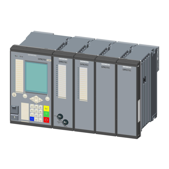
SIPROTEC 5
Operation
V7.80 and higher
Manual
C53000-G5040-C003-9
Preface
Open Source Software
Table of Contents
First Steps
Expanding Devices
Fitting the Devices
Handling of Plug-In Modules
Using On-Site Operation Panel
Using DIGSI 5
Operation Using a Browser-Based User
Interface
Operation in the Operating State
Commissioning
Maintenance, On-the-Spot Assistance and
Test
Security Settings in the Device
Glossary
Index
1
2
3
4
5
6
7
8
9
10
11
Advertisement
Table of Contents

Related Manuals for Siemens SIPROTEC 5 V7.80


Summary of Contents for Siemens SIPROTEC 5 V7.80
- Page 1 Preface Open Source Software Table of Contents SIPROTEC 5 First Steps Operation Expanding Devices Fitting the Devices V7.80 and higher Handling of Plug-In Modules Using On-Site Operation Panel Manual Using DIGSI 5 Operation Using a Browser-Based User Interface Operation in the Operating State Commissioning Maintenance, On-the-Spot Assistance and Test...
- Page 2 Although including rights created by patent grant or registration of a Siemens AG has made best efforts to keep the document as utility model or a design, are reserved. precise and up-to-date as possible, Siemens AG shall not...
-
Page 3: Preface
Preface Purpose of the Manual This manual describes the operation of the device and gives information about safety, commissioning and operation as well as checks and tests. Target Audience Protection system engineers, commissioning engineers, persons entrusted with the setting, testing and main- tenance of automation, selective protection and control equipment, and operational crew in electrical installa- tions and power plants. - Page 4 The SIPROTEC 5 catalog describes the system features and the devices of SIPROTEC 5. • Selection guide for SIPROTEC and Reyrolle The selection guide offers an overview of the device series of the Siemens protection devices, and a device selection table. Indication of Conformity...
- Page 5 Preface Additional Support For questions about the system, please contact your Siemens sales partner. Support Our Customer Support Center provides a 24-hour service. Phone: +49 (180) 524-7000 Fax: +49 (180) 524-2471 E-Mail: support.energy@siemens.com Training Courses Inquiries regarding individual training courses should be addressed to our Training Center:...
- Page 6 The equipment (device, module) may be used only for such applications as set out in the catalogs and the technical description, and only in combination with third-party equipment recommended and approved by Siemens. Problem-free and safe operation of the product depends on the following: •...
-
Page 7: Open Source Software
License Conditions provide for it you can order the source code of the Open Source Software from your Siemens sales contact - against payment of the shipping and handling charges - for a period of at least 3 years since purchase of the Product. We are liable for the Product including the Open Source Software contained in it pursuant to the license conditions applicable to the Product. - Page 8 SIPROTEC 5, Operation, Manual C53000-G5040-C003-9, Edition 06.2018...
-
Page 9: Table Of Contents
Table of Contents Preface................................3 Open Source Software..........................7 First Steps..............................15 Unpacking, Repacking, Returning, and Storing..............16 Incoming Inspection ......................18 Electrical Inspection......................19 Expanding Devices............................. 21 Flush-Mounting Devices....................22 2.1.1 Basic Rules for Expansion..................... 22 2.1.2 Expanding 1st Device Row................... 23 Surface-Mounted Devices with Integrated On-Site Operation Panel........ - Page 10 Table of Contents 4.1.3 Removing ........................63 4.1.4 Replacement....................... 65 Using On-Site Operation Panel........................67 General..........................68 Overview of Operator Elements and Display Elements............69 Displays for Indication and Control..................77 Structure of the Menu....................... 79 Menu Tree ........................80 Notification Windows and Dialogs ..................82 Displaying Device Mode....................
- Page 11 Table of Contents Logs..........................136 8.5.1 General........................136 8.5.2 Operational Log......................137 8.5.3 Fault Log........................139 8.5.4 Ground-Fault Log...................... 140 8.5.5 Setting-History Log....................142 8.5.6 User Log........................144 8.5.7 Security Log......................145 8.5.8 Device-Diagnosis Log....................146 8.5.9 Communication Log....................148 8.5.10 Communication-Supervision Log................149 8.5.11 Motor-Starting Log....................
- Page 12 Table of Contents 8.9.7 Acquisition Blocking and Manual Updating..............184 8.9.8 Status Display ......................186 8.9.9 Setting a Marker......................187 8.9.10 Assignment of Authorizations with Confirmation ID........... 187 8.9.11 Control with Function Keys..................188 Commissioning............................189 Overview........................190 Test Suite Integrated in the Device.................. 191 9.2.1 Test Functions......................
- Page 13 Table of Contents 10.4.4 Upgrading the Configuration Version................. 229 10.5 Test and Diagnostics....................... 234 10.5.1 Establishing Test Mode ..................... 234 10.5.2 Switching Test Mode On and Off ................235 10.5.3 Switching Block Monitoring Direction On and Off............235 Security Settings in the Device.........................239 11.1 Security Design.......................
- Page 14 SIPROTEC 5, Operation, Manual C53000-G5040-C003-9, Edition 06.2018...
-
Page 15: First Steps
First Steps Unpacking, Repacking, Returning, and Storing Incoming Inspection Electrical Inspection SIPROTEC 5, Operation, Manual C53000-G5040-C003-9, Edition 06.2018... -
Page 16: Unpacking, Repacking, Returning, And Storing
The relative humidity must be at a level where condensed water and ice are prevented from forming. ² Siemens recommends that you observe a restricted storage temperature range of +10°C to +35°C, in ² order to prevent the electrolytic capacitors used in the power supply from aging prematurely. - Page 17 First Steps 1.1 Unpacking, Repacking, Returning, and Storing If the device has been in storage for more than 2 years, connect it to an auxiliary voltage for 1 to 2 days. ² This action will cause the electrolytic capacitors to form on the printed circuit board assemblies again. If devices are to be shipped elsewhere, you can reuse the transport packaging.
-
Page 18: Incoming Inspection
First Steps 1.2 Incoming Inspection Incoming Inspection Siemens recommends that you check devices which are not assembled. Safety Notes DANGER Danger during incoming inspection Noncompliance with the safety notes, can result in death, severe injury or considerable material damage. Comply with all given safety notes when carrying out the incoming inspection. -
Page 19: Electrical Inspection
Join several on-site operation panels to one another with firm contact. ² Siemens recommends the use of contact washers on painted metal mounting walls. If the mounting wall is not metallic, place a metal layer, for example a metal sheet, between the mounting wall and the on- site operation panels. - Page 20 First Steps 1.3 Electrical Inspection Safety Notes DANGER Danger during electrical inspection Noncompliance with the safety notes will result in death, severe injury or considerable material damage. Comply with all given safety notes when carrying out the electrical inspection. ² Please note that hazardous voltages are present when you perform the electrical inspection.
-
Page 21: Expanding Devices
Expanding Devices Flush-Mounting Devices Surface-Mounted Devices with Integrated On-Site Operation Panel Surface-Mounted Devices with Detached On-Site Operation Panel SIPROTEC 5, Operation, Manual C53000-G5040-C003-9, Edition 06.2018... -
Page 22: Flush-Mounting Devices
Expanding Devices 2.1 Flush-Mounting Devices Flush-Mounting Devices Basic Rules for Expansion 2.1.1 NOTE Prepare the following tools for the device expansion: • Phillips screwdriver size PZ1 and PZ2 • Screwdriver DIN 4 x 0.8 • During assembly, use the prescribed torques Comply with the following basic rules when expanding devices: Always fit the base module on the left in the 1st device row. -
Page 23: Expanding 1St Device Row
Expanding Devices 2.1 Flush-Mounting Devices Expanding 1st Device Row 2.1.2 Preparation NOTE Reordered modules are not contained in the original device configuration. Use DIGSI to perform the corre- sponding extension in the Hardware and Protocols Editor. Carry out the steps described in this chapter if you wish to expand an installed device later on with expan- sion modules. -
Page 24: Surface-Mounted Devices With Integrated On-Site Operation Panel
Expanding Devices 2.2 Surface-Mounted Devices with Integrated On-Site Operation Panel Surface-Mounted Devices with Integrated On-Site Operation Panel Basic Rules for Expansion 2.2.1 NOTE Prepare the following tools for the device expansion: • Phillips screwdriver size PZ1 and PZ2 • Screwdriver DIN 4 x 0.8 •... -
Page 25: Expanding 1St Device Row
Expanding Devices 2.2 Surface-Mounted Devices with Integrated On-Site Operation Panel [dwauize1-040211-01.tif, 2, --_--] Figure 2-2 Device Row Distance frame Mounting bracket Distance frame on base module rotated by 180 Expanding 1st Device Row 2.2.2 Preparation NOTE Reordered modules are not contained in the original device configuration. Use DIGSI to perform the corre- sponding extension in the Hardware and Protocols Editor. - Page 26 Expanding Devices 2.2 Surface-Mounted Devices with Integrated On-Site Operation Panel Remove the device completely. ² Assembling the On-Site Operation Panel into One Block [dwaublo1-040211-01.tif, 2, --_--] Figure 2-3 On-Site Operation Panel Fitted on Mounting Bracket Place the 2 mounting brackets intended for expansion in parallel to one another on a flat surface. ²...
- Page 27 Expanding Devices 2.2 Surface-Mounted Devices with Integrated On-Site Operation Panel Fit the device back onto the wall without fastened on-site operation panels. ² Use the supplied grounding cable to connect the expansion module with the device and reconnect the ² device to service ground.
-
Page 28: Surface-Mounted Devices With Detached On-Site Operation Panel
Expanding Devices 2.3 Surface-Mounted Devices with Detached On-Site Operation Panel Surface-Mounted Devices with Detached On-Site Operation Panel Basic Rules for Expansion 2.3.1 NOTE Prepare the following tools for the device expansion: • Phillips screwdriver size PZ1 and PZ2 • Screwdriver DIN 4 x 0.8 •... -
Page 29: Expanding 1St Device Row
Expanding Devices 2.3 Surface-Mounted Devices with Detached On-Site Operation Panel [dwabosop-040211-01.vsd, 2, en_US] Figure 2-5 Detached On-Site Operation Panel Expanding 1st Device Row 2.3.2 Preparation NOTE Reordered modules are not contained in the original device configuration. Use DIGSI to perform the corre- sponding extension in the Hardware and Protocols Editor. - Page 30 Expanding Devices 2.3 Surface-Mounted Devices with Detached On-Site Operation Panel Swivel the expansion module in the direction of the device so that the bottom snap-in spring engages. ² Bolt the on-site operation panels of the 2 modules to one another through the contact tab. ²...
-
Page 31: Fitting The Devices
Fitting the Devices Flush-Mounting Devices Surface-Mounted Devices with Integrated On-Site Operation Panel Surface-Mounted Devices with Detached On-Site Operation Panel SIPROTEC 5, Operation, Manual C53000-G5040-C003-9, Edition 06.2018... -
Page 32: Flush-Mounting Devices
Fitting the Devices 3.1 Flush-Mounting Devices Flush-Mounting Devices Drilling Patterns and Dimension Specifications [dw_z1_1-3, 2, en_US] Figure 3-1 Cut-Out Widths and Drilling Pattern – 1/3 Device, 1st Device Row SIPROTEC 5, Operation, Manual C53000-G5040-C003-9, Edition 06.2018... - Page 33 Fitting the Devices 3.1 Flush-Mounting Devices [dw_z1_1-2, 2, en_US] Figure 3-2 Cut-Out Widths and Drilling Pattern – 1/2 Device, 1st Device Row SIPROTEC 5, Operation, Manual C53000-G5040-C003-9, Edition 06.2018...
- Page 34 Fitting the Devices 3.1 Flush-Mounting Devices [dw_z1_2-3, 2, en_US] Figure 3-3 Cut-Out Widths and Drilling Pattern – 2/3 Device, 1st Device Row SIPROTEC 5, Operation, Manual C53000-G5040-C003-9, Edition 06.2018...
- Page 35 Fitting the Devices 3.1 Flush-Mounting Devices [dw_z1_5-6, 2, en_US] Figure 3-4 Cut-Out Widths and Drilling Pattern – 5/6 Device, 1st Device Row [dw_z1_1-1, 3, en_US] Figure 3-5 Cut-Out Widths and Drilling Pattern – 1/1 Device, 1st Device Row SIPROTEC 5, Operation, Manual C53000-G5040-C003-9, Edition 06.2018...
- Page 36 Fitting the Devices 3.1 Flush-Mounting Devices All drillings in the area of the specific device cut-out widths (see Table 3-1) must comply with the dimensions in the corresponding figures. [dw_z2_2-6, 2, en_US] Figure 3-6 Cut-Out Widths and Drilling Pattern – 1/3 Device, 2nd Device Row SIPROTEC 5, Operation, Manual C53000-G5040-C003-9, Edition 06.2018...
- Page 37 Fitting the Devices 3.1 Flush-Mounting Devices [dw_z2_3-6, 2, en_US] Figure 3-7 Cut-Out Widths and Drilling Pattern – 1/2 Device, 2nd Device Row [dw_z2_4-6, 2, en_US] Figure 3-8 Cut-Out Widths and Drilling Pattern – 2/3 Device, 2nd Device Row SIPROTEC 5, Operation, Manual C53000-G5040-C003-9, Edition 06.2018...
- Page 38 Fitting the Devices 3.1 Flush-Mounting Devices [dw_z2_5-6, 2, en_US] Figure 3-9 Cut-Out Widths and Drilling Pattern – 5/6 Device, 2nd Device Row [dw_z2_6-6, 3, en_US] Figure 3-10 Cut-Out Widths and Drilling Pattern – 1/1 Device, 2nd Device Row SIPROTEC 5, Operation, Manual C53000-G5040-C003-9, Edition 06.2018...
- Page 39 Drilling Pattern – 1/1 Devices, 1st and 2nd Device Row Siemens recommends a drilling space of at least 55 mm (2.17 in) between the 1st and 2nd device row. Due to the connecting-cable length, the maximum space may be approx. 80 mm (3.15 in). The length of the cable is 890 mm (35.04 in) from the center of the plug to the center of the plug.
-
Page 40: Fitting Devices
Fitting the Devices 3.1 Flush-Mounting Devices Width of the Assembly Opening in mm (in Inches) 5/6 device (base module with 3 expansion modules) mm (14.61 +0.08 1/1 device (base module with 4 expansion modules) mm (17.6 +0.08 Table 3-2 Variable Housing Widths Dimension a Housing Widths in mm (in Inches) (Total Width: Housing Width + 4.6 mm (0.18 in)) -
Page 41: Activating The Battery
Fitting the Devices 3.1 Flush-Mounting Devices NOTE Use a PZ2-size Phillips screwdriver. For each module, you need 4 fastening screws with a shank diameter of 4 mm (0.16 in). WARNING Danger due to device being improperly screw-fastened Incomplete and careless screw-fastening can lead to death, severe injury, and considerable material damage. -
Page 42: Tightening Torques Of Fastening Screws
Join several on-site operation panels to one another with firm contact. ² Siemens recommends the use of contact washers on painted metal assembly walls. If the assembly wall is not metallic, place a metal layer, for example a metal sheet, between the assembly wall and the on-site operation panels. -
Page 43: Surface-Mounted Devices With Integrated On-Site Operation Panel
Fitting the Devices 3.2 Surface-Mounted Devices with Integrated On-Site Operation Panel Surface-Mounted Devices with Integrated On-Site Operation Panel Drilling Patterns and Dimension Specifications (Modular Device) [dwosopin-070211-01.tif, 3, en_US] Figure 3-14 1/3 Surface-Mounted Device with Integrated On-Site Operation Panel, Dimensions in the Side and Front Views NOTE For surface-mounted devices, make sure that the drillings fit for a screw of the size M6. - Page 44 Fitting the Devices 3.2 Surface-Mounted Devices with Integrated On-Site Operation Panel [dwbohrge-1_3.vsd, 2, en_US] Figure 3-15 Drilling Pattern of a 1/3 Surface-Mounted Device – 1st Device Row [dwbohrge-1_2.vsd, 2, en_US] Figure 3-16 Drilling Pattern of a 1/2 Surface-Mounted Device – 1st Device Row SIPROTEC 5, Operation, Manual C53000-G5040-C003-9, Edition 06.2018...
- Page 45 Fitting the Devices 3.2 Surface-Mounted Devices with Integrated On-Site Operation Panel [dwbohrge-2_3.vsd, 2, en_US] Figure 3-17 Drilling Pattern of a 2/3 Surface-Mounted Device – 1st Device Row [dwbohrge-5_6.vsd, 2, en_US] Figure 3-18 Drilling Pattern of a 5/6 Surface-Mounted Device – 1st Device Row SIPROTEC 5, Operation, Manual C53000-G5040-C003-9, Edition 06.2018...
- Page 46 Fitting the Devices 3.2 Surface-Mounted Devices with Integrated On-Site Operation Panel [dwbohrge-070211-01.tif, 3, en_US] Figure 3-19 Drilling Pattern of a 1/1 Surface-Mounted Device – 1st Device Row [dw_z2_bohr_1-3.vsd, 2, en_US] Figure 3-20 Drilling Pattern of a 1/3 Surface-Mounted Device – 2nd Device Row SIPROTEC 5, Operation, Manual C53000-G5040-C003-9, Edition 06.2018...
- Page 47 Fitting the Devices 3.2 Surface-Mounted Devices with Integrated On-Site Operation Panel [dw_z2_bohr_1-2.vsd, 2, en_US] Figure 3-21 Drilling Pattern of a 1/2 Surface-Mounted Device – 2nd Device Row [dw_z2_bohr_2-3.vsd, 2, en_US] Figure 3-22 Drilling Pattern of a 2/3 Surface-Mounted Device – 2nd Device Row SIPROTEC 5, Operation, Manual C53000-G5040-C003-9, Edition 06.2018...
- Page 48 Fitting the Devices 3.2 Surface-Mounted Devices with Integrated On-Site Operation Panel [dw_z2_bohr_5-6.vsd, 2, en_US] Figure 3-23 Drilling Pattern of a 5/6 Surface-Mounted Device – 2nd Device Row SIPROTEC 5, Operation, Manual C53000-G5040-C003-9, Edition 06.2018...
- Page 49 Fitting the Devices 3.2 Surface-Mounted Devices with Integrated On-Site Operation Panel [dw_z2_bohr_1-1.vsd, 2, en_US] Figure 3-24 Drilling Pattern of a 1/1 Surface-Mounted Device – 2nd Device Row SIPROTEC 5, Operation, Manual C53000-G5040-C003-9, Edition 06.2018...
- Page 50 Fitting the Devices 3.2 Surface-Mounted Devices with Integrated On-Site Operation Panel Dimensions, Non-Modular Surface-Mounted Device [dw_console side view.vsd, 3, en_US] Figure 3-25 Non-Modular Surface-Mounted Device with Integrated On-Site Operation Panel, Dimensions from the Side and Front Views Drilling Pattern, Non-Modular Surface-Mounted Device NOTE For surface-mounted devices, make sure that the drillings fit for a screw of the size M6.
-
Page 51: Fitting Devices
Fitting Devices 3.2.1 Preparations NOTE Siemens recommends detaching the on-site operation panels before fitting the device. Fit the on-site oper- ation panels after completing wiring and checks. NOTE Use a PZ2-size Phillips screwdriver. For each module, you need 4 fastening screws with a shank diameter of 6 mm (0.16 in). -
Page 52: Activating The Battery
Fitting the Devices 3.2 Surface-Mounted Devices with Integrated On-Site Operation Panel Align the device in the oblong holes. Ensure that screw-fastening is complete at all intended bolting ² points. Screw the device onto the top mounting bracket with the fastening screws. ²... - Page 53 Fitting the Devices 3.2 Surface-Mounted Devices with Integrated On-Site Operation Panel NOTE Make sure that the cables and lines of extra-low voltage circuits are laid sufficiently far away from power network circuits. Torques for Other Screw Types Screw Type Torque M4 x 20 1.2 Nm M4 x 8...
-
Page 54: Surface-Mounted Devices With Detached On-Site Operation Panel
Fitting the Devices 3.3 Surface-Mounted Devices with Detached On-Site Operation Panel Surface-Mounted Devices with Detached On-Site Operation Panel Drilling Patterns and Dimension Specifications of the On-Site Operation Panels You can find more information on the drilling patterns for the devices in section Drilling Patterns and Dimen- sion Specifications (Modular Device) , Page [dw_z1_osop_1-3, 1, en_US]... - Page 55 Fitting the Devices 3.3 Surface-Mounted Devices with Detached On-Site Operation Panel [dw_z1_osop_2-3, 1, en_US] Figure 3-29 Drilling Pattern of the On-Site Operation Panel of the 2/3 Device [dw_z1_osop_5-6, 1, en_US] Figure 3-30 Drilling Pattern of the On-Site Operation Panel of the 5/6 Device SIPROTEC 5, Operation, Manual C53000-G5040-C003-9, Edition 06.2018...
- Page 56 Fitting the Devices 3.3 Surface-Mounted Devices with Detached On-Site Operation Panel [dw_z1_osop_1-1, 1, en_US] Figure 3-31 Drilling Pattern of the On-Site Operation Panel of the 1/1 Device [dwosopab-070211-01.tif, 3, en_US] Figure 3-32 Surface-Mounted Device with Detached On-Site Operation Panel, Dimensions in the Side and Front Views Refer to Table 3-2...
-
Page 57: Fitting The Devices
The distance between the installation location of the device and that of the on-site operation panel must not exceed 5 m. Join the on-site operation panels to one another with firm contact. Siemens recommends the use of contact washers on painted metal assembly walls. If the assembly wall is not metallic, place a metal layer, for example a metal sheet, between the assembly wall and the on-site operation panel;... -
Page 58: Activating The Battery
Fitting the Devices 3.3 Surface-Mounted Devices with Detached On-Site Operation Panel Plug the connecting cable into the on-site operation panel of the basic module. ² Guide the connecting cable through the cut-out in the assembly wall. ² Place the 2 contact washers on the top fastening holes. ²... - Page 59 Fitting the Devices 3.3 Surface-Mounted Devices with Detached On-Site Operation Panel Type of Line Current Voltage Terminal with Voltage Terminal with Terminal Spring-Loaded Terminals Screw Connection Stranded wires with bootlace ferrules 2.7 Nm 1.0 Nm 0.6 Nm or pin-type lugs 2.0 Nm 1.0 Nm –...
- Page 60 SIPROTEC 5, Operation, Manual C53000-G5040-C003-9, Edition 06.2018...
-
Page 61: Handling Of Plug-In Modules
Handling of Plug-In Modules Installation, Removal, Replacement SIPROTEC 5, Operation, Manual C53000-G5040-C003-9, Edition 06.2018... -
Page 62: Installation, Removal, Replacement
Handling of Plug-In Modules 4.1 Installation, Removal, Replacement Installation, Removal, Replacement Fasteners 4.1.1 The fasteners of the plug-in modules are shown in the following figure regarding the example of an installed module and an empty, covered slot. [le_fxing_elements, 1, --_--] Figure 4-1 Fasteners EMC spring contact... -
Page 63: Removing
Handling of Plug-In Modules 4.1 Installation, Removal, Replacement CAUTION Exercise caution with laser beams of the optical plug-in modules. Noncompliance with the safety notes can result in medium-severe or slight injuries. Do not look directly into the optical fiber terminals of the active optical plug-in modules, not even with ²... - Page 64 Handling of Plug-In Modules 4.1 Installation, Removal, Replacement Preparing Removal DANGER Risk of live voltage when removing the plug-in modules. Noncompliance with the safety notes will result death or severe injuries. Remove plug-in modules on the electrically deactivated device only. ²...
-
Page 65: Replacement
Handling of Plug-In Modules 4.1 Installation, Removal, Replacement Replacement 4.1.4 Preparing for Replacement DANGER Danger due to live voltage when replacing the plug-in modules. Noncompliance with the safety notes will result in death or severe injuries. Install plug-in modules on the electrically deactivated device only. ²... - Page 66 Handling of Plug-In Modules 4.1 Installation, Removal, Replacement NOTE If you have not cabled the optical fiber plug-in modules, then seal the terminals with protective covers. This prevents soiling of the terminals. SIPROTEC 5, Operation, Manual C53000-G5040-C003-9, Edition 06.2018...
-
Page 67: Using On-Site Operation Panel
Using On-Site Operation Panel General Overview of Operator Elements and Display Elements Displays for Indication and Control Structure of the Menu Menu Tree Notification Windows and Dialogs Displaying Device Mode Display of Routings and Status SIPROTEC 5, Operation, Manual C53000-G5040-C003-9, Edition 06.2018... -
Page 68: General
Using On-Site Operation Panel 5.1 General General All SIPROTEC 5 devices can be operated via the DIGSI 5 interface of your PC and via the on-site operation panel. This is available optionally as an integrated and detached on-site operation panel. The on-site operation panel is characterized by a flat, compact design. -
Page 69: Overview Of Operator Elements And Display Elements
Using On-Site Operation Panel 5.2 Overview of Operator Elements and Display Elements Overview of Operator Elements and Display Elements On-Site Operation Panel of the Base and 1/3 Module [le_base_module, 2, --_--] Figure 5-2 Base and 1/3 Module in Standard, US, and China Design Operating state display Display in 2 design versions Keypad with navigation keys... - Page 70 Using On-Site Operation Panel 5.2 Overview of Operator Elements and Display Elements Operator Element/Display Function Element Display of operability Green LED (Run) The device is switched on. The presence of the external auxiliary voltage is indicated to you. Red LED (Error) The device is not ready to run or a failure is present.
- Page 71 Using On-Site Operation Panel 5.2 Overview of Operator Elements and Display Elements Operator Element/Display Function Element Navigation keys By pressing or holding down the navigation keys, you can navigate in the menus, lists and the graphical images (default display, control display). Menus and lists (press key): •...
- Page 72 Using On-Site Operation Panel 5.2 Overview of Operator Elements and Display Elements Operator Element/Display Function Element Navigational aid The footer of the display shows you the authorized navigation directions depending on current display level. Selection dialogs: In selection dialogs, you are offered selection options one below the other. Example parameter Mode (off/on/test).
- Page 73 Using On-Site Operation Panel 5.2 Overview of Operator Elements and Display Elements Operator Element/Display Function Element Numerical keys and convertible function keys This keypad is used for entering numerical values (with or without decimal point). You can activate actions of function keys using these keys. The keys <1>...
- Page 74 Using On-Site Operation Panel 5.2 Overview of Operator Elements and Display Elements Operator Element/Display Function Element Function-keys menu The configured assignment of function keys is visible in the function key menu. The assignment of function keys <F1> to <F8> is defined in DIGSI 5. They have different defaults depending on the application template.
- Page 75 Using On-Site Operation Panel 5.2 Overview of Operator Elements and Display Elements On-Site Operation Panel of the Base Modules [dwerwmod-040211-01.tif, 2, --_--] Figure 5-3 Expansion Module 16 monochrome LEDs Labeling strips 2 key switches 8 monochrome LEDs 8 push-buttons The following table gives you a detailed explanation of the function of the operator and display elements. Operator Element/Display Element Meaning 16 parameterizable LEDs...
- Page 76 Using On-Site Operation Panel 5.2 Overview of Operator Elements and Display Elements Operator Element/Display Element Meaning 8 parameterizable LEDs • Monochrome (red) Keypad • Keypad with programmable function keys to perform actions quickly. Next to the keypad, there are labeling strips for user-defined labels.
-
Page 77: Displays For Indication And Control
Using On-Site Operation Panel 5.3 Displays for Indication and Control Displays for Indication and Control Displays Displays for indication and control offer you the possibility of quickly obtaining an overview of important oper- ating modes. You can configure a total of up to 10 displays in DIGSI 5 using the display editor. The following contents are available here: •... - Page 78 Using On-Site Operation Panel 5.3 Displays for Indication and Control [scabzstb-100211-01.tif, 1, en_US] Figure 5-5 Control Display A ready-to-run device with large graphic display shows you the control display defined as the standard after booting. By pressing and holding down the left navigation key, you get to the control display defined as standard.
-
Page 79: Structure Of The Menu
Using On-Site Operation Panel 5.4 Structure of the Menu Structure of the Menu [scmnuebr-030914-01, 2, en_US] Figure 5-6 Example Main Menu Title bar with name of menu Position display and total number of available menu items List of menu items with numbering on the right edge (shortcut) Base bar with the display of permissible navigation directions and assignment of softkeys The current position in the menu is marked with brighter font on a dark background. -
Page 80: Menu Tree
Using On-Site Operation Panel 5.5 Menu Tree Menu Tree The menu tree consists of the main menu and several levels of submenus. To navigate in the menu use the keys on the operation panel of the base module. Main Menu The main menu structure is firmly set and is not changeable. - Page 81 Using On-Site Operation Panel 5.5 Menu Tree The settings are grouped in corresponding submenus according to their assignment to existing function groups (for example, line 1). You will find information about viewing and changing settings in chapter 8.4.1 General. Binary I/O Menu Selecting the Binary I/O menu provides you with the option to see the routing to the binary inputs, binary outputs and signals displayed.
-
Page 82: Notification Windows And Dialogs
Using On-Site Operation Panel 5.6 Notification Windows and Dialogs Notification Windows and Dialogs Notification Windows The notification windows appear briefly in the base bar to give you important information during on-site oper- ation and close automatically. For example, they contain the following information: [scmitfen-080413-01.tif, 1, en_US] Figure 5-7 Examples of Notification Windows... - Page 83 Using On-Site Operation Panel 5.6 Notification Windows and Dialogs NOTE If you do not confirm the dialog with a softkey, the action you wish to achieve is canceled after a previously set time. The prior state is restored. SIPROTEC 5, Operation, Manual C53000-G5040-C003-9, Edition 06.2018...
-
Page 84: Displaying Device Mode
Using On-Site Operation Panel 5.7 Displaying Device Mode Displaying Device Mode Not Initialized Device (As-Delivered Condition) SIPROTEC 5 devices are not initialized in the as-delivered condition. If a non-initialized device is connected to the auxiliary voltage and started, then the following information is shown on the display: •... - Page 85 Using On-Site Operation Panel 5.7 Displaying Device Mode You can also feed in the test signals using a digital test equipment. Digital test equipment offers you multiple test programs and test sequences. Process Mode The process mode is the normal operation of the device. SIPROTEC 5, Operation, Manual C53000-G5040-C003-9, Edition 06.2018...
-
Page 86: Display Of Routings And Status
Using On-Site Operation Panel 5.8 Display of Routings and Status Display of Routings and Status You can route logic information from the SIPROTEC 5 device to binary inputs, binary outputs and LEDs. With the menu item Binary I/O of the device you can display the routing of the logical signals and their status. In order to display the routings in the SIPROTEC 5 device, proceed as follows: •... - Page 87 Using On-Site Operation Panel 5.8 Display of Routings and Status [scbinipt5-260814-01, 1, en_US] Figure 5-11 List of Binary Inputs • Use the navigation keys to select the binary input, for example, Binaryinput1.1. All signals routed to Binaryinput1.1 are displayed as a list (see Figure 5-13).
- Page 88 Using On-Site Operation Panel 5.8 Display of Routings and Status [scranma1-260814-01, 1, en_US] Figure 5-12 Entry in the Information Routing Figure 5-13 shows that [L] active without voltage for the signal >Ext. trip initiation was parameterized. In the Line function group, the Overvoltage protection (ANSI 59) is also operated. In addi- tion, the Binaryinput1.1 can also block this protection function.
- Page 89 Using On-Site Operation Panel 5.8 Display of Routings and Status Example of a Circuit Breaker A circuit breaker can have the status open or closed. Figure 5-14 displays the various properties of the circuit breaker in the information routing of DIGSI 5. [scranma2-260814-01, 1, en_US] Figure 5-14 Properties of the Circuit Breaker...
- Page 90 Using On-Site Operation Panel 5.8 Display of Routings and Status Example of a Transformer Tap Changer You can also use a binary input to display the tap position of the transformer tap changer. In this case, you must set the X (routed) property in the DIGSI 5 Information routing (see figure below). X (routed) means that the binary input was routed.
-
Page 91: Using Digsi 5
Using DIGSI 5 General Operator Actions in the Offline and Online Area Initializing a Device Transferring Device Data from the PC to the Device Changing Data on the Online Device Retrieving Fault Records and Log Contents SIPROTEC 5, Operation, Manual C53000-G5040-C003-9, Edition 06.2018... -
Page 92: General
Using DIGSI 5 6.1 General General DIGSI 5 is the engineering and operating tool for all SIPROTEC 5 devices. With DIGSI 5, you create system topologies, configure hardware and communication networks and perform many other tasks. You carry out all engineering tasks offline from your PC without needing a SIPROTEC 5 device. You transfer all data online to the device later –... - Page 93 Using DIGSI 5 6.1 General • Individual devices • Editors • Setting sheets • Tables • Actions • Folder You have access to all data and tools via the individual symbols. A double-click is enough and the symbols will show setting values of protection functions, start actions such as loading of parameter values or open one of the editors.
-
Page 94: Operator Actions In The Offline And Online Area
Using DIGSI 5 6.2 Operator Actions in the Offline and Online Area Operator Actions in the Offline and Online Area You can execute operator actions in the offline configurations or online on the device. NOTE To avoid unintentional changes and switching operations during operation, some operator actions are protected by a confirmation ID. - Page 95 Using DIGSI 5 6.2 Operator Actions in the Offline and Online Area NOTE If you change setting values or routings in online devices, you must activate them in the device. This ensures consistent acceptance of data. SIPROTEC 5, Operation, Manual C53000-G5040-C003-9, Edition 06.2018...
-
Page 96: Initializing A Device
Using DIGSI 5 6.3 Initializing a Device Initializing a Device NOTE Initialization is possible, for example, via the USB interface or port J of the device. NOTE The physical connection between PC and SIPROTEC 5 device may be done only 1 to 1. If your PC has several free USB interfaces, you can connect only one single SIPROTEC 5 device. -
Page 97: Transferring Device Data From The Pc To The Device
Using DIGSI 5 6.4 Transferring Device Data from the PC to the Device Transferring Device Data from the PC to the Device NOTE If the protection devices are connected to the engineering PC, the transfer of device data to one or more devices is possible. - Page 98 Using DIGSI 5 6.4 Transferring Device Data from the PC to the Device NOTE If you wish to use another Ethernet interface port other than port J, in Device Information select the inter- face with which DIGSI 5 should communicate with your SIPROTEC 5 device. Alternatively, you can select the following path for the setting of the Ethernet address.
-
Page 99: Changing Data On The Online Device
Using DIGSI 5 6.5 Changing Data on the Online Device Changing Data on the Online Device Always execute changes in the project tree of the selected device and load the changes to the device. Proceed as follows: In your project, click the node of the selected device. ²... -
Page 100: Retrieving Fault Records And Log Contents
Using DIGSI 5 6.6 Retrieving Fault Records and Log Contents Retrieving Fault Records and Log Contents Proceed in online mode as described in chapter 6.4 Transferring Device Data from the PC to the Device Load the parameterization and read process data from the device. Link the matching offline configuration in your project to your online device. -
Page 101: Operation Using A Browser-Based User Interface
Operation Using a Browser-Based User Interface General Operation Example Additional Application Options Settings SIPROTEC 5, Operation, Manual C53000-G5040-C003-9, Edition 06.2018... -
Page 102: General
Operation Using a Browser-Based User Interface 7.1 General General Apart from the use of an engineering tool such as DIGSI 5 or SICAM TOOLBOX II for configuration and mainte- nance, SIPROTEC 5 devices provide a Web front end that can be used with a standard Web browser. The browser-based user interface is a comprehensive commissioning and monitoring tool that provides an easy- to-understand display of the most important measured data. -
Page 103: Operation
Operation Using a Browser-Based User Interface 7.2 Operation Operation If you are familiar with the structure of the settings in DIGSI 5 and the on-site operation, you will be able to navigate through the same structure (for example, function groups, function blocks, and display on the on-site operation panel). - Page 104 Operation Using a Browser-Based User Interface 7.2 Operation Once the Web browser is successfully connected to the device, the following dialog (RBAC) appears: [scwebmonitor, 1, en_US] Figure 7-2 Logon Dialog for the Browser-Based User Interface • Enter the user name. •...
- Page 105 Operation Using a Browser-Based User Interface 7.2 Operation After a successful logon, the following menu selection is available. [scwebmonitor1, 2, en_US] Figure 7-3 Menu Selection for the Browser-Based User Interface You can view the appropriate settings by selecting the individual entries. NOTE If you do not undertake any action in the browser-based user interface within a defined time lapse, the Web browser disconnects from the device.
- Page 106 Operation Using a Browser-Based User Interface 7.2 Operation Button Meaning Use this button to control an LED reset. Use this button to start an export (for example, for operational indications). Use this button to access the home screen and the list box. Use these buttons to switch the measured and statistical values to primary, secondary, or percentage values.
- Page 107 Operation Using a Browser-Based User Interface 7.2 Operation You can also navigate via the list box. You can directly open settings and information that you would like to view. [scnaviwebmon, 2, en_US] Figure 7-5 List Box The additional buttons of the browser-based user interface are described in the following: •...
- Page 108 Operation Using a Browser-Based User Interface 7.2 Operation • Monitoring: The following logs are displayed using the Logs button. You can display the contents of a log by clicking the desired log. Depending on the device the following logs are available: –...
- Page 109 Operation Using a Browser-Based User Interface 7.2 Operation • Measured values: 3 buttons are available. – Operational measured values: An overview of the function groups is displayed via the Operational measured values button. The measured values can be displayed by clicking the desired function group. [scwebmonitor15, 2, en_US] Figure 7-8 Operational Measured Values...
- Page 110 Operation Using a Browser-Based User Interface 7.2 Operation [scwebmonitor16, 2, en_US] Figure 7-9 Functional Measured Values – Statistics: An overview of the function groups providing statistical values is displayed via the Statistics button. The statistical values, for example, device operating hours, can be displayed by clicking the desired function group (see Figure 7-10).
- Page 111 Operation Using a Browser-Based User Interface 7.2 Operation • Terminal assignment: 3 buttons are available. – Binary inputs: An overview of the connected binary inputs is displayed via the Binary inputs button. You can display the assignment of the binary inputs for this module by clicking a button in the left section (for example, base module).
- Page 112 Operation Using a Browser-Based User Interface 7.2 Operation – LEDs: An overview of the connected LEDs is displayed via the LEDs button. You can display the assignment of the LEDs for this module by clicking a button in the left section (for example, base module). [scwebmonitor10LED, 1, en_US] Figure 7-13 Assignment of LEDs:...
- Page 113 Operation Using a Browser-Based User Interface 7.2 Operation • Engineering: An overview of the function groups is displayed via the Settings button. The settings of a function group are displayed by clicking the appropriate button. [scwebmonitor19, 2, en_US] Figure 7-14 Displaying Settings SIPROTEC 5, Operation, Manual C53000-G5040-C003-9, Edition 06.2018...
-
Page 114: Example
Operation Using a Browser-Based User Interface 7.3 Example Example To illustrate working with the browser-based user interface, the procedure is shown using the following example (reading operational indications). There must be a communication connection between the PC and the device. •... -
Page 115: Additional Application Options
Comparing the values of 2 or more devices • Checking a setting value against a user-defined setting as to whether the setting value differs from the default value specified by Siemens • Querying a value to adjust a test case, for example, to preset the tripping current •... -
Page 116: Settings
Operation Using a Browser-Based User Interface 7.5 Settings Settings You can set the parameters for the browser-based user interface separately for the communication interface (Port J). If the device has an Ethernet communication module, you can also use Port E, Port F, Port N, or Port P. The important parameters are the IP address and the port number of the interface used to communicate between the PC and the browser-based user interface. -
Page 117: Operation In The Operating State
Operation in the Operating State Overview Safety Notes and Access Rights Operation Options Indications Logs Edit Measured and Metered Values Fault Recording Change Device Settings Control System on Site SIPROTEC 5, Operation, Manual C53000-G5040-C003-9, Edition 06.2018... -
Page 118: Overview
Operation in the Operating State 8.1 Overview Overview This chapter describes the handling of a SIPROTEC 5 device in the operating state. It contains the following information: • Reading information from the device • Affecting the functions of the device in the operating state •... -
Page 119: Safety Notes And Access Rights
Operation in the Operating State 8.2 Safety Notes and Access Rights Safety Notes and Access Rights Safety Notes 8.2.1 Authorized Operational Crew DANGER Danger due to inadmissible or improper operator control actions Noncompliance with the safety notes will result in death or severe injuries. Only personnel who are skilled electricians with precise knowledge of the system may operate devices ²... -
Page 120: Operation Options
Operation in the Operating State 8.3 Operation Options Operation Options General 8.3.1 The device is operated via a DIGSI 5 PC or directly on the on-site operation panel. You have the following oper- ating options during operation: • Readout of indications •... - Page 121 Operation in the Operating State 8.3 Operation Options Procedure First identify all devices reachable via the PC communication interfaces. You can identify your device via ² the DIGSI 5 project tree. Establish a connection to a selected device. ² If needed, you can assign a selected device to an existing project. ²...
-
Page 122: Offline Operation Using Digsi 5
Operation in the Operating State 8.3 Operation Options If you click Update Device Data, you can read the parameter set and the process data of the device. The ² device data is loaded and the view completed. You can fully operate and set the connected devices under Online access in the DIGSI 5 project tree. ²... - Page 123 Operation in the Operating State 8.3 Operation Options NOTE For a device to be editable offline, you must first have created it in a project. After successful loading of the configuration, the device restarts automatically. Procedure From the project tree, select the project containing the device to be operated. ²...
-
Page 124: Using The On-Site Operation Panel
Operation in the Operating State 8.3 Operation Options [scgerzu-070916-01, 1, en_US] Figure 8-5 Connecting to the Device and Loading the Configuration in Offline Mode Using the On-Site Operation Panel 8.3.4 You can operate the device directly on the on-site operation panel even without a DIGSI 5 PC. A numerical keypad, navigation and function keys are available to you for this purpose. -
Page 125: Indications
Operation in the Operating State 8.4 Indications Indications General 8.4.1 During operation, indications deliver information about operational states. These include: • Measured data • Power-system data • Device supervisions • Device functions • Function procedures during testing and commissioning of the device In addition, indications give an overview of important fault events after a failure in the system. - Page 126 Operation in the Operating State 8.4 Indications [scoprlog-090413-01.tif, 1, en_US] Figure 8-6 On-Site Display of an Indication List (Example: Operational Indications) Menu Path Main menu → Indications → Operational log Fault log Ground-fault log Setting changes User indications 1 User indications 2 Motor-starting indications Main Menu →...
-
Page 127: Reading Indications From The Pc With Digsi 5
Operation in the Operating State 8.4 Indications Reading Indications from the PC with DIGSI 5 8.4.3 Procedure Menu Path (Project) Project → Device → Process data → Log → Operational log Setting changes Fault log User indications 1 User indications 2 Motor-starting log Ground-fault log Online access →... -
Page 128: Displaying Indications
Operation in the Operating State 8.4 Indications Setting Relative Time Reference Reference the display of log entries, if needed, to the real time of a specific entry. In this way, you deter- ² mine a relative time for all other indications. The real-time stamps of events remain unaffected. Displaying Indications 8.4.4 Displayed indications in DIGSI 5 and on the on-site operation panel are supplemented with the following infor-... - Page 129 Operation in the Operating State 8.4 Indications Indications in DIGSI 5 Information Device Display Information Log for parameter changes Time stamp (date and time), Time stamp (date and time), Relative time, Function structure, Entry number, Name, Function structure, Value Name, Value, Quality, Cause,...
-
Page 130: Spontaneous Indication Display In Digsi 5
Indication number Number of the indication that occurred in the device. This number increments continuously and is necessary for an analysis by Siemens. Indication Message text Function structure Path of the signal with the signal name... -
Page 131: Spontaneous Fault Display On The On-Site Operation Panel
Operation in the Operating State 8.4 Indications [scspnmld-230211-01, 2, en_US] Figure 8-8 Displaying Spontaneous Device Indications in DIGSI 5 Spontaneous Fault Display on the On-Site Operation Panel 8.4.6 After a fault, the most important data of the last fault can be displayed automatically on the device display without further operational measures. -
Page 132: Stored Indications In The Siprotec 5 Device
Operation in the Operating State 8.4 Indications Displayed Information Explanation Fault distance Display of the measured fault-location distance. Acknowledgement of the Spontaneous Fault Display on the Device After faults, the last occurred fault is always displayed to you. In cases where more than one circuit breaker is configured, several stored fault displays can be present after faults, with the latest being displayed. - Page 133 Operation in the Operating State 8.4 Indications You are offered the following options: Table 8-5 Overview of Routing Options Routing Options LEDs Description (active) The signal is routed as active with voltage. (active) The signal is routed as active without voltage. (unlatched) The signal is routed as unlatched.
-
Page 134: Acknowledgment Of Stored Indications
Operation in the Operating State 8.4 Indications Acknowledgment of Stored Indications 8.4.8 Acknowledgment on the On-Site Operation Panel Acknowledgment via LED Reset key Operating the key first causes the activation of all LEDs (LED test) when pressed, and when released, the reset- ting of all stored indications. -
Page 135: Test Mode And Influence Of Indications On Substation Automation Technology
Operation in the Operating State 8.4 Indications Acknowledgment of Stored Indications via Binary Inputs Acknowledgment by binary input >LED Reset switches on all LEDs (LED Test). When the signal reverts, all stored indications, stored LEDs, output contacts, and spontaneous fault indications are reset. Acknowledgment of Stored Indications with DIGSI 5 You can acknowledge stored indications via DIGSI 5 in online mode. -
Page 136: Logs
Operation in the Operating State 8.5 Logs Logs General 8.5.1 Indications are saved in logs inside the device and are available for later analyses. Different logs allow catego- rization of indication logging based on operating states (for example, operational and fault logs) and based on fields of application. -
Page 137: Operational Log
Operation in the Operating State 8.5 Logs [scinfpuf-191012-01, 2, en_US] Figure 8-14 Indication Configuration in DIGSI 5 (Example: Ground-Fault Log, Column G) For non-configurable logs (for example, setting-history logs) scope and type of logged indications are described separately (see following chapter about logs). Operational Log 8.5.2 Operational indications are information that the device generates during operation. - Page 138 Operation in the Operating State 8.5 Logs [scbetrmd-030211-01, 1, en_US] Figure 8-15 Reading the Operational Log with DIGSI 5 Reading on the Device via the On-Site Operation Panel • To reach the operational log via the main menu, use the navigation keys of the on-site operation panel. Main Menu →...
-
Page 139: Fault Log
Operation in the Operating State 8.5 Logs [scoperlog1-081217-01, 1, en_US] Figure 8-16 On-Site Display of an Indication List (Example: Operational Indications) Deletability The operational log of your SIPROTEC 5 device can be deleted. This is done usually after testing or commis- sioning the device. -
Page 140: Ground-Fault Log
Operation in the Operating State 8.5 Logs Apart from the recording of fault indications in the fault log, spontaneous display of fault indications of the last fault on the device display is also done. You will find details about this in chapter 8.4.6 Spontaneous Fault Display on the On-Site Operation Panel. - Page 141 Operation in the Operating State 8.5 Logs Reading from the PC with DIGSI 5 • To reach the ground-fault log of your SIPROTEC 5 device, use the project-tree window. Project → Device → Process data → Logs → Ground-fault log The status of the device-diagnosis log last loaded from the ground-fault log is shown to you.
-
Page 142: Setting-History Log
Operation in the Operating State 8.5 Logs Deletability The ground-fault log of your SIPROTEC 5 device can be deleted. Read details about this in chapter 8.5.12 Saving and Deleting the Logs. Configurability The indication scope of the ground-fault log is configured in a specifically defined column of the information routing (matrix) of DIGSI 5: Target →... - Page 143 Operation in the Operating State 8.5 Logs [schislog-090413-01.tif, 1, en_US] Figure 8-21 Reading the Setting-History Log on the On-Site Operation Panel of the Device Indication Categories in the Setting-History Log For this log, there is selected information that is stored in case of successful as well as unsuccessful setting changes.
-
Page 144: User Log
Operation in the Operating State 8.5 Logs User Log 8.5.6 With the user-defined log (up to 2), you have the possibility of individual indication logging parallel to the operational log. This is helpful, for example, in special monitoring tasks but also in the classification into different areas of responsibility of the logs. -
Page 145: Security Log
Operation in the Operating State 8.5 Logs Deletability The user-defined log of your SIPROTEC 5 device can be deleted. You will find details about this in chapter 8.5.12 Saving and Deleting the Logs. Configuration of a User-Defined Log The indication capacity of a created user-defined log can be configured freely in the associated column of the information routing (matrix) of DIGSI 5: Target →... -
Page 146: Device-Diagnosis Log
Operation in the Operating State 8.5 Logs [scsecmld-180816-01, 1, en_US] Figure 8-25 Reading the Security Indications with DIGSI 5 Reading on the Device through the On-Site Operation Panel • To access the security log from the main menu, use the navigation keys on the on-site operation panel. Main Menu →... - Page 147 Operation in the Operating State 8.5 Logs • Required maintenance (for example, battery supervision) • Identified hardware defects • Compatibility problems Up to 500 indications can be stored in the device-diagnosis log. In normal operation of the device, it is suffi- cient for diagnostic purposes to follow the entries of the operational log.
-
Page 148: Communication Log
Operation in the Operating State 8.5 Logs NOTE • The device-diagnosis log cannot be deleted! • The logged indications are preconfigured and cannot be changed! Communication Log 8.5.9 The logging of the respective status such as ensuing faults, test and diagnosis operation, and communication capacity utilizations is done for all hardware-based configured communication interfaces. -
Page 149: Communication-Supervision Log
Operation in the Operating State 8.5 Logs [sccommlg-090413-01.tif, 1, en_US] Figure 8-30 Reading the Communication Log on the On-Site Operation Panel of the Device Deletability The communication logs of your SIPROTEC 5 device can be deleted. Read details about this in chapter 8.5.12 Saving and Deleting the Logs. -
Page 150: Motor-Starting Log
Operation in the Operating State 8.5 Logs [sc_comsuperv, 1, en_US] Figure 8-31 Reading the Communication-Supervision Log with DIGSI 5 Reading on the Device via the On-Site Operation Panel • To reach the operational log via the main menu, use the navigation keys of the on-site operation panel. Main menu →... - Page 151 Operation in the Operating State 8.5 Logs • To update (synchronization with the device) click the button Update in the headline of the indication list (Figure 8-32 a)). [scmotmlp-160713-01, 1, en_US] Figure 8-32 Reading the Motor-Starting Log with DIGSI 5 Reading on the Device through the On-Site Operation Panel •...
-
Page 152: Saving And Deleting The Logs
Operation in the Operating State 8.5 Logs Configurability The motor-starting log is only present in the Motor function group. There is no column for the motor-starting log in the DIGSI information routing. The entries in the motor-starting log are preconfigured and cannot be changed. - Page 153 Operation in the Operating State 8.5 Logs [scoprlog-090413-01.tif, 1, en_US] Figure 8-34 Deleting the Operational Log on the On-Site Operation Panel • You can navigate within the displayed indication list using the navigation keys (up/down) on the on-site operation panel. •...
-
Page 154: Edit Measured And Metered Values
Operation in the Operating State 8.6 Edit Measured and Metered Values Edit Measured and Metered Values Overview of Measured and Metered Values 8.6.1 The SIPROTEC 5 devices have numerous measured and metered values. The following Table 8-9 gives you an overview of the scope and sequencing principle. -
Page 155: Reading Measured Values And Metered Values
Operation in the Operating State 8.6 Edit Measured and Metered Values Measured / Metered Description Values Energy values These metered values are determined for active and reactive energy. Restore time, restore interval and counting mode are adjustable. Restoration can be initiated via a binary input. - Page 156 Operation in the Operating State 8.6 Edit Measured and Metered Values You can read the measured values in the function group Circuit Breaker 1 as follows: • In the main menu of the device display, switch to Main menu → Measured values → Circuit breaker 1 The following measured-value group is displayed for you, and you can find the available measured and metered values in Table...
-
Page 157: Setting And Resetting Energy Values
Operation in the Operating State 8.6 Edit Measured and Metered Values [scmswesi-080413-01.tif, 1, en_US] Figure 8-35 Example of the Measured-Value View for the Function Group Line 1 Setting and Resetting Energy Values 8.6.3 Setting and resetting energy values on the device: To set and reset on the device use the Measured values menu. -
Page 158: Setting And Resetting User-Defined Metered Values
Operation in the Operating State 8.6 Edit Measured and Metered Values Enter the desired value in the Current value column. The input value is converted to the data format ² according to IEC 61850. Because of the associated quantization, the resulting display value can differ from the input. -
Page 159: Resetting Min./Max./Average Values
Operation in the Operating State 8.6 Edit Measured and Metered Values Enter the desired value in the Current value column. The input value is converted to the data format ² according to IEC 61850. Because of the associated quantization, the resulting display value can differ from the input. - Page 160 Operation in the Operating State 8.6 Edit Measured and Metered Values Enter the desired value in the Current value column. The input value is converted to the data format ² according to IEC 61850. In addition, the input value is rounded to 6 digits. The display is limited to 6 digits.
-
Page 161: Fault Recording
Operation in the Operating State 8.7 Fault Recording Fault Recording General 8.7.1 Fault data relates to events or records that are recorded during a device fault. Sampled values of analog meas- urement inputs and calculated measured values of the device are recorded in the fault recording. A fault record can also used for recording binary events as traces. -
Page 162: Displaying Fault Records
Operation in the Operating State 8.7 Fault Recording NOTE • Take note that when accessing via online access points the fault records read replace all fault records previously shown in the window. If you wish to save special fault records, then export the fault records (see chapter 8.5.12 Saving and Deleting the Logs). -
Page 163: Saving And Exporting Fault Records
Operation in the Operating State 8.7 Fault Recording [scttrecd-080211-01.tif, 2, en_US] Figure 8-39 Displaying a Fault Record with the COMTRADE Viewer Saving and Exporting Fault Records 8.7.4 For the analysis of important fault records you can save them as files on your DIGSI 5 PC. You have 2 export options available in DIGSI 5. -
Page 164: Deleting Fault Records
Operation in the Operating State 8.7 Fault Recording Deleting Fault Records 8.7.5 The recorded fault records are managed in a ring buffer in the device. So that new records can always be created securely, the oldest records are deleted automatically when the maximum storage capacity is reached. However, you can also delete targeted fault records. -
Page 165: Configuration Of The Start Criterion
Operation in the Operating State 8.7 Fault Recording [sccnfrec-080413-01.tif, 1, en_US] Figure 8-40 Configuration of Fault-Record Channels with DIGSI 5 NOTE The sampled values of analog measuring inputs (currents and voltages) are not freely configurable in the fault record. The values are specified automatically by the routing of measuring points to the analog input modules of the device. - Page 166 Operation in the Operating State 8.7 Fault Recording [scusrrec-051016-01, 1, en_US] Figure 8-41 User-Defined Configuration of the Start Criterion for Fault Recording • You can also set parameters for the start criterion via an external start signal in the Fault recorder func- tion.
-
Page 167: Change Device Settings
Operation in the Operating State 8.8 Change Device Settings Change Device Settings Date and Time Synchronization 8.8.1 The integrated date and time synchronization of your SIPROTEC 5 device allows you to assign the precise time of events to an internally maintained device time. Events in the logs are stamped with the device time. These time stamps are also transmitted during transmission to substation automation technology or via a protection interface. -
Page 168: Setting Time Keeping Parameters
Operation in the Operating State 8.8 Change Device Settings [scdttime-080413-01.tif, 1, en_US] Figure 8-44 Date and Time Setting • From the Date format menu item, select a display option. • To change the format, press the Change softkey. • Enter the change and then confirm the entry by selecting the Ok softkey. The Date and Time menu items show you the current values with ongoing update. - Page 169 Operation in the Operating State 8.8 Change Device Settings [scztkonf-030311-01.tif, 1, en_US] Figure 8-45 Time Settings via DIGSI 5 Settings on the Device Using the On-Site Operation Panel You can only access some of the settings using the on-site operation panel while the device is being operated. To reach the settings for time synchronization from the main menu, use the navigation keys on the on-site operation panel.
-
Page 170: Status And Monitoring Of Time Keeping
Operation in the Operating State 8.8 Change Device Settings NOTE Make sure that the settings for the time sources coincide with the actual hardware configuration of your SIPROTEC 5 device. In any event, incorrect settings cause the status indications of time sources to pick up. Status and Monitoring of Time Keeping 8.8.4 Time Information in the DIGSI 5... -
Page 171: Setting The Contrast Of The Device Display
Operation in the Operating State 8.8 Change Device Settings [scdttime-080413-01.tif, 1, en_US] Figure 8-48 Date and Time Setting The Date & Time menu items show you the current values, which are continually updated. You can also change entries here. Time Synchronization Indications Internal time synchronization is monitored cyclically. - Page 172 Operation in the Operating State 8.8 Change Device Settings Changing the Units System on the On-Site Operation Panel • To reach the settings dialog for selecting the units, select the Localization menu in Device functions. • To select the units system, press the Change softkey. •...
-
Page 173: Changing Confirmation Ids
Operation in the Operating State 8.8 Change Device Settings [scsprums-040613-01.tif, 1, en_US] Figure 8-52 Language Change with DIGSI 5 • The setting is accepted in the device through Load configuration in devices. • When prompted, enter the confirmation ID and finally click Ok. The operation panel language changes automatically after it is downloaded from the PC to the device. -
Page 174: Setting Function Settings
Operation in the Operating State 8.8 Change Device Settings Table 8-10 Default Setting of Confirmation IDs Operating Range Default Setting Read access 111111 Set/operate 222222 Switching (operation) 333333 Switching (unlocked) 444444 Switching authority 666666 8.8.8 Setting Function Settings Enter the function settings of your SIPROTEC 5 device preferably using the DIGSI 5. You have access here to all possible settings. - Page 175 Operation in the Operating State 8.8 Change Device Settings [scstfugr-030311-01.tif, 1, en_US] Figure 8-55 Function Settings in DIGSI 5 • When you are finished changing your settings, load the entire device configuration into the device. • To do so, right-click the Load configuration in device context menu. •...
- Page 176 Operation in the Operating State 8.8 Change Device Settings Online Settings via DIGSI 5 You should always use the online setting if you want to change individual function settings of a device in operation. To reach the function settings of your SIPROTEC 5 device, use the project-tree window. •...
-
Page 177: Settings Group Switching
Operation in the Operating State 8.8 Change Device Settings Settings Group Switching 8.8.9 For different applications you can save the respective function settings in so-called Settings groups, and if necessary enable them quickly. You can save up to 8 different settings groups in the device. In the process, only one settings group is active at any given time. - Page 178 Operation in the Operating State 8.8 Change Device Settings [scesakpa-080413-01.tif, 1, en_US] Figure 8-59 Setting the Active Settings Group on the On-Site Operation Panel • Use the navigation keys to select the settings group to be activated from the displayed list of possible settings.
- Page 179 Operation in the Operating State 8.8 Change Device Settings The communication protocols IEC 60870-5-103, IEC 60870-5-104, IEC 61850, DNP or Modbus TCP can be used for switching the settings groups via a communication connection. In order to use a CFC chart for switching, you must create a new CFC chart in DIGSI 5. Create the CFC chart in the DIGSI 5 project tree under Name of the device →...
-
Page 180: Control System On Site
Operation in the Operating State 8.9 Control System on Site Control System on Site General 8.9.1 You can execute switching device control via a connected substation automation system and through DIGSI 5. You can also control the device directly via the keyboard. The large graphic display is best suited for this purpose but control is also possible with the small display. -
Page 181: Switching Authority
Operation in the Operating State 8.9 Control System on Site Menu Item Submenu Meaning Interlocking One line for every Display of interlocking status of the switching devices with switching device the letters S, D, P and B. • S = Check of switching authority •... -
Page 182: Control With Graphic Display
Operation in the Operating State 8.9 Control System on Site Go to the menu item Switching mode. ² Select Interlocked or Non-interlocked and confirm with Ok. ² You can set this switchover after entering the confirmation ID. ² Control with Graphic Display 8.9.5 Devices with a graphic display can depict a single-line diagram of the field in the control display, see Figure... -
Page 183: Control With Small Display
Operation in the Operating State 8.9 Control System on Site [scauswqa-090413-01.tif, 1, en_US] Figure 8-63 Selecting a Switching Device in the Control Diagram You can also initiate a control action via the navigation keys after selecting a switching device. To do so, select Open or Close in the menu and confirm with Ok. [scsteuvo-090413-01.tif, 1, en_US] Figure 8-64 Initiating Control Action... -
Page 184: Acquisition Blocking And Manual Updating
Operation in the Operating State 8.9 Control System on Site [scklndis-090413-01.tif, 1, en_US] Figure 8-65 Control from the List on the Small Display 8.9.7 Acquisition Blocking and Manual Updating During commissioning, maintenance, or testing, a brief interruption of the connection between the logical signals and binary inputs may be useful. - Page 185 Operation in the Operating State 8.9 Control System on Site [scstatus-310816-01, 1, en_US] Figure 8-67 Activating Manual Update [scstatu2-310816-01, 1, en_US] Figure 8-68 Selecting Position The manually updated position of the switching device will be displayed. [scstatu3-310816-01, 1, en_US] Figure 8-69 Position of the Switching Device NOTE For security reasons, manual updating is possible only directly through the on-site operation panel of the...
-
Page 186: Status Display
Operation in the Operating State 8.9 Control System on Site [scbeerfa-190215, 1, en_US] Figure 8-70 Input Signals >Acquisition Block and >Release Acquisition Block & Manual Updating on the Switching Device NOTE Interlockings are carried out with the status changes of the switching device. Remove acquisition blocking again manually. -
Page 187: Setting A Marker
Operation in the Operating State 8.9 Control System on Site [scstatus-090413-01.tif, 1, en_US] Figure 8-71 Status Display of Switching Devices The meaning of the status columns is as follows: AB = Acquisition blocking active (acquisition blocking for the switching device is set) MU = Manual update (switching device was manually updated) CH = Chatter blocking active (Chatter blocking has been activated and is still set) 8.9.9... -
Page 188: Control With Function Keys
Operation in the Operating State 8.9 Control System on Site [scaktvor-210311-01.tif, 1, en_US] Figure 8-73 Assignment of Confirmation IDs Table 8-13 Confirmation IDs Name Description Seting/operate Authorization to change settings on the device display and DIGSI 5 Switching (operation) To prevent unintentional switching of combined protection and control devices, this general authorization for switching on site is available. -
Page 189: Commissioning
Commissioning Overview Test Suite Integrated in the Device Initial Startup Secondary Tests Primary Tests SIPROTEC 5, Operation, Manual C53000-G5040-C003-9, Edition 06.2018... -
Page 190: Overview
Commissioning 9.1 Overview Overview This chapter contains information about the commissioning of the SIPROTEC 5 device. Test functions inte- grated in the device support you during testing, simplify testing processes and reduce testing times. You will get an overview of the numerous possibilities of initial startup in chapter 9.3 Initial Startup. -
Page 191: Test Suite Integrated In The Device
Commissioning 9.2 Test Suite Integrated in the Device Test Suite Integrated in the Device Test Functions 9.2.1 After you complete the initial startup (see chapter 9.3 Initial Startup), you can access the test functions inte- grated in the device. To do this, establish connection to the online device. In the project tree, open the Folder Test Suite. -
Page 192: Testing Current And Voltage Inputs
Commissioning 9.2 Test Suite Integrated in the Device [scgemoaz-210611-01.tif, 1, en_US] Figure 9-2 Project Navigation • Select the previous mode in the working area Device information under Device mode. • Click the Restart button. Testing Current and Voltage Inputs 9.2.2 If you click in the project tree according to Figure 9-1 on the menu item Analog inputs , a representation visu-... -
Page 193: Testing Protection Functions
Feed the test quantities to the terminals (for example, exchange terminals in the control cabinet) using multiphase test equipment. Siemens recommends a test with the rated values and the infeed of current and voltage in phase. The test functions from 10 % of the rated quantity. - Page 194 Commissioning 9.2 Test Suite Integrated in the Device Additionally you can define a ramp for each phase via amplitude, phase or frequency via the ramp functions. You can still define 3 various harmonic superimpositions per phase. This allows the setting of ramps within one test step.
-
Page 195: Creating Signals For Communication Interfaces
Commissioning 9.2 Test Suite Integrated in the Device [scprscfk-160413-01.tif, 1, en_US] Figure 9-5 Testing a Protection Function (Example, Overvoltage Protection) NOTE The device remains in commissioning mode until you set the device in the process mode consciously or until the internal monitoring time (statement of time) has expired. You reach the process mode by clicking the link in the upper right of the working area. - Page 196 Commissioning 9.2 Test Suite Integrated in the Device WARNING Warning of danger due to unauthorized switching states Noncompliance with safety notes means that death, serious injuries, or considerable material damage can occur. Primary tests may be done only by personnel who are skilled electricians and who are familiar with the ²...
-
Page 197: Circuit-Breaker Test
Commissioning 9.2 Test Suite Integrated in the Device Circuit-Breaker Test 9.2.6 To test circuit breakers, go to Test suite and open the Circuit-breaker test menu item. The existing ² circuit breakers then appear in the operating range (see Figure 9-7). You can bypass the interlock of the circuit breaker. - Page 198 Commissioning 9.2 Test Suite Integrated in the Device [scgerinf-100413-01.tif, 1, en_US] Figure 9-8 Device-Information Worksheet • Device information: General information about the device such as device name, product code and serial number is indicated here. If the device uses Ethernet, you can select at this point the IP address of the device through which DIGSI 5 communicates with the device (port J, this setting only available in offline mode).
- Page 199 Commissioning 9.2 Test Suite Integrated in the Device • Diagnostic information: Here detailed information on the individual hardware and software components are stored. NOTE The device remains in commissioning mode until you set the device in the process mode consciously or until the internal monitoring time (statement of time) has expired.
-
Page 200: Initial Startup
Familiarize yourself with the project and the device settings before you execute the next steps. Take the following procedure as your guide: Install the DIGSI 5 operating program on your PC/laptop. For commissioning, Siemens recommends the ² DIGSI 5 variant Premium. -
Page 201: Initializing Device And Verifying Basic Status
If you use circuiting you can view the static reports on the systems control. Create an overview of the settings or the routing in the individual menu items. Siemens recommends ² doing this when opening the device in DIGSI. -
Page 202: Testing Readiness For Operation
9.2 Test Suite Integrated in the Device. Siemens recommends the following procedure in this order: Testing binary inputs and outputs ² Check that the connection from the transmission terminal to the device is correct and the binary inputs and outputs as well. -
Page 203: Secondary Tests
Commissioning 9.4 Secondary Tests Secondary Tests Scope of Inspection and Methodology 9.4.1 The secondary test objectives are: • Checking the transformer burdens, checking the transformer data of the main current and voltage trans- former • Checking the routing of signals to the most varied targets (binary inputs (BI), binary outputs (BO), LEDs, and interfaces) •... - Page 204 Since protection functions can be assigned to different protection function groups, check the interaction between function groups as well. If you have created your own application template or modified the delivered template, Siemens recommends that you check the interaction. The application templates provided with the device have been tested.
-
Page 205: Testing Interfaces In The Compound System
Commissioning 9.4 Secondary Tests • Since measured values are also displayed apart from switching devices in the display diagram, check the proper assignment of measured values by feeding and changing the test quantities. • Tap changer position commands and control commands for arc-suppression coils can be checked via DIGSI 5. -
Page 206: Primary Tests
Commissioning 9.5 Primary Tests Primary Tests Testing System Integration 9.5.1 A requirement for the primary test is that prior tests (chapter 9.3 Initial Startup 9.4 Secondary Tests) have been completed successfully. Take note of the following before starting the test: General Notes DANGER Danger due to hazardous voltages during the operation of electric devices... - Page 207 Commissioning 9.5 Primary Tests CAUTION You must ground the device at the protective grounding terminal before making the connections. There may be hazardous voltages in all switching components linked to the power supply and to measurand or test quantities. There may be hazardous voltages in the device (capacitor storage of the current supply) even after disconnecting the supply voltage.
-
Page 208: Methodical Procedure For Primary Tests Of Functions
Commissioning 9.5 Primary Tests NOTE Before you perform this test, make sure that the respective system part is isolated and a switching opera- tion can be executed safely. Check the feedback once you have activated the switching device. ² In the menu, go to Test-suite → Analog inputs and check the voltage and current inputs. The relevant ²... -
Page 209: Testing Measured Values During Operation
Commissioning 9.5 Primary Tests NOTE Using wiring modifications, switch the primary system to the de-energized state. You can do tests specific to protection functions via the operational measured values. To do this, click the Functional meas. values tab. In a differential protection function, the differential ²... - Page 210 SIPROTEC 5, Operation, Manual C53000-G5040-C003-9, Edition 06.2018...
-
Page 211: Maintenance, On-The-Spot Assistance And Test
Maintenance, On-the-Spot Assistance and Test 10.1 Execute Checks 10.2 Error Search and Correction 10.3 Replace and Return Defective Device 10.4 Update Firmware and Configuration 10.5 Test and Diagnostics SIPROTEC 5, Operation, Manual C53000-G5040-C003-9, Edition 06.2018... -
Page 212: Execute Checks
No special maintenance is required for SIPROTEC 5 devices. The only maintenance measure is to replace batteries. NOTE To avoid data loss, Siemens recommends replacing the device battery with the device supply voltage switched on. All measurement- and signal-processing circuits are designed full-static. All input modules are also static, and the binary outputs are equipped with protective covers. - Page 213 Maintenance, On-the-Spot Assistance and Test 10.1 Execute Checks If the protection equipment has picked up or disabled an error, you can verify this through the fault ² record and the fault log. This is how the protection equipment demonstrates its correct operation in the operating state.
-
Page 214: Error Search And Correction
10.2.1 Procedure If the device indicated an error, then Siemens recommends that you proceed as follows: If no LED on the operation panel of the device lights up, then verify as follows: Check whether the auxiliary voltage on the corresponding connections has an adequate amount and ²... -
Page 215: Measures For Error Correction
Maintenance, On-the-Spot Assistance and Test 10.2 Error Search and Correction Reading the Device Data with DIGSI 5 Select the device in the project tree. ² Double-click Device information in the project tree. ² In the Device information tab, you can find the data on your SIPROTEC 5 device. [scgerdia-230816-01, 1, en_US] Figure 10-2 Reading Device Information... - Page 216 Maintenance, On-the-Spot Assistance and Test 10.2 Error Search and Correction NOTE Ensure that the protection and control functions are deactivated in fallback mode. Fallback mode is evident from the termination of the life contact, the Error LED, and the Fallback mode header in the device display.
- Page 217 Maintenance, On-the-Spot Assistance and Test 10.2 Error Search and Correction [scmbfb5ein-030914-01, 1, en_US] Figure 10-4 Structure of the Fallback Submenu • Device information The menu item Device information provides data about the SIPROTEC 5 device, for example, device name, serial number, device type, and product key. •...
- Page 218 Maintenance, On-the-Spot Assistance and Test 10.2 Error Search and Correction [schwswfb-020914-01, 3, en_US] Figure 10-5 Menu Items for HW/SW Information • Mainboard This menu item informs you about the board type and the details concerning the version of the main- board.
-
Page 219: Error Indications
Maintenance, On-the-Spot Assistance and Test 10.2 Error Search and Correction • I/O modules A list of the input/output modules being used can be found under the menu item I/O Modules. You can select each individual printed circuit board assembly and, for example, have the slot or the terminal posi- tion displayed. - Page 220 Maintenance, On-the-Spot Assistance and Test 10.2 Error Search and Correction Device-Diagnostic Log Hardware failure at measuring-transducer module position E/F/M/N/P: Contact the repair service. A faulty display configuration was detected: Synchronize the hardware configuration of the device with DIGSI. Offset failure at a measuring input: •...
- Page 221 Maintenance, On-the-Spot Assistance and Test 10.2 Error Search and Correction Device-Diagnostic Log Maximum number of line disconnectors exceeded Maximum number of transfer bus disconnectors exceeded Maximum number of sectionalizing disconnectors exceeded Maximum number of level 2 disconnectors exceeded Maximum number of load breaking switches exceeded Maximum number of bays exceeded Auxiliary power-supply failure: Check the external power supply.
- Page 222 The number of signals in a GOOSE dataset/application is too big. Reduce the number of signals in the related dataset and upload a valid configuration. Battery failure: Change the device battery. To avoid data loss, Siemens recommends replacing the device battery with the device supply voltage switched on. Function-point violation: No adequate number of function points.
-
Page 223: Replace And Return Defective Device
1.1 Unpacking, Repacking, Returning, and Storing). • Return all of the defective module to your Siemens sales partner. NOTE If the base module is incomplete, for example if terminals are missing, it cannot be taken back. SIPROTEC 5, Operation, Manual... -
Page 224: Update Firmware And Configuration
DIGSI 5 device drivers contain both the firmware and the configuration data. Siemens recommends performing the firmware update on the device locally. If you wish to start the firmware update remotely, use a data circuit with a transmission rate of at least 1 Mbit/s. - Page 225 Maintenance, On-the-Spot Assistance and Test 10.4 Update Firmware and Configuration [scdddcom-260716-01, 1, en_US] Figure 10-6 Selecting the Device Drivers If the process has been completed without errors, the following dialog will appear: [scsucddd-260716-01, 1, en_US] Figure 10-7 Import Status • Click the OK button.
- Page 226 Maintenance, On-the-Spot Assistance and Test 10.4 Update Firmware and Configuration [scgetrvw-250716-01, 1, en_US] Figure 10-8 Manage Device Drivers Concluding Firmware Update NOTE Before doing a firmware update of your SIPROTEC 5 device or the communication modules, back up the data and the configuration of the device using DIGSI 5 via Connect device and retrieve data! NOTE The device will not carry out any functions during the update.
- Page 227 Maintenance, On-the-Spot Assistance and Test 10.4 Update Firmware and Configuration [scausfiw-011116-01, 1, en_US] Figure 10-9 Context Menu for Firmware Update As an alternative, you can update the firmware for all the devices on the network at the same time. • To do this, double-click in the project tree the menu item Load firmware to devices.
- Page 228 Maintenance, On-the-Spot Assistance and Test 10.4 Update Firmware and Configuration [scfwupsd-280716-01, 2, en_US] Figure 10-11 Selecting Firmware Update • Click the Update button to see the version differences. • Enter the passwords based on the access protection in use. • Select the device or the communication module that must be updated.
-
Page 229: Special Features When Handling Protocols
Maintenance, On-the-Spot Assistance and Test 10.4 Update Firmware and Configuration [scfwdvlo-280716-01, 1, en_US] Figure 10-14 Status of Firmware Update After the firmware update of the device and the communication modules, all firmware components of the device have been updated. You can find more information on this in Structure of the HW/SW Information Menu Item, Page 217. - Page 230 Maintenance, On-the-Spot Assistance and Test 10.4 Update Firmware and Configuration [scupgpar-041016-01, 1, en_US] Figure 10-15 Context Menu for the Upgrade • Select the desired device configuration and the corresponding communication configuration by selecting the available version: [scupgcnf-290716-01, 1, en_US] Figure 10-16 Version Selection •...
- Page 231 Maintenance, On-the-Spot Assistance and Test 10.4 Update Firmware and Configuration [scaktolf-290716-01, 1, en_US] Figure 10-17 Upgrade Progress Once the procedure has completed, the following 2 tabs appear: [scupginf-260716-01, 1, en_US] Figure 10-18 Overview of the Upgrade The 2nd tab shows information, possible errors and warnings regarding the upgrade procedure. SIPROTEC 5, Operation, Manual C53000-G5040-C003-9, Edition 06.2018...
- Page 232 Maintenance, On-the-Spot Assistance and Test 10.4 Update Firmware and Configuration [scupgwrn-260716-01, 1, en_US] Figure 10-19 Information, Errors and Warnings Loading the Updated Configuration Finally, you must load the updated configuration into the device Proceed as follows: • Select the device in the project tree. •...
- Page 233 Maintenance, On-the-Spot Assistance and Test 10.4 Update Firmware and Configuration Subsequently the dialog for the confirmation query appears. • Enter the confirmation ID. • Click Ok to confirm. If the data was successfully transmitted, the device is restarted. SIPROTEC 5, Operation, Manual C53000-G5040-C003-9, Edition 06.2018...
-
Page 234: Test And Diagnostics
Maintenance, On-the-Spot Assistance and Test 10.5 Test and Diagnostics 10.5 Test and Diagnostics Establishing Test Mode 10.5.1 Safety Instructions DANGER Danger due to the execution of test functions Noncompliance with safety instructions will result in death, serious physical injury, or considerable material damage. -
Page 235: Switching Test Mode On And Off
Maintenance, On-the-Spot Assistance and Test 10.5 Test and Diagnostics NOTE Depending on the device layout, not all test functions are always available. The execution of test functions is protected by a confirmation ID. Switching Test Mode On and Off 10.5.2 Procedure If the test mode is switched on, indications transmitted via communication interfaces are labeled with an addi- tional test bit, provided this is supported by the protocol. - Page 236 Maintenance, On-the-Spot Assistance and Test 10.5 Test and Diagnostics [scblkdir-080413-01.tif, 1, en_US] Figure 10-23 Block Monitoring Direction at the Device • Activate block monitoring direction via a binary input. • Activate block monitoring direction via DIGSI 5. SIPROTEC 5, Operation, Manual C53000-G5040-C003-9, Edition 06.2018...
- Page 237 Maintenance, On-the-Spot Assistance and Test 10.5 Test and Diagnostics [scmemspr-081015, 1, en_US] Figure 10-24 Block Monitoring Direction via DIGSI 5 When switching block monitoring direction on or off, an indication is output in the left area of the status bar. Bar segments inform you as well about the progress of the process.
- Page 238 SIPROTEC 5, Operation, Manual C53000-G5040-C003-9, Edition 06.2018...
-
Page 239: Security Settings In The Device
Security Settings in the Device 11.1 Security Design 11.2 Multi-Level Safety Concept 11.3 Security Settings 11.4 Confirmation ID 11.5 Connection Password 11.6 Authentication, Connection Password, and Confirmation ID During Operation 11.7 Using Connection Passwords and Confirmation IDs 11.8 Recording of Cyber-Security Events 11.9 Operational Security and Access Control 11.10... -
Page 240: Security Design
Security Settings in the Device 11.1 Security Design 11.1 Security Design Due to the increasing integration of bay units in Ethernet-based communication network, you must secure the communication against internal failures and attacks from outside. The specifications published by the North American Electric Reliability Council for critical infrastructure protection - NERC-CIP, for short - and the white paper published by the German Association of Energy and Water Management (BDEW) contain requirements for the safe operation of devices in critical communications infrastructure. -
Page 241: Multi-Level Safety Concept
Security Settings in the Device 11.2 Multi-Level Safety Concept 11.2 Multi-Level Safety Concept DIGSI 5 offers many useful functions for the configuration and testing of your SIPROTEC 5 devices. Constant password prompts are not sensible during this phase. During operation, however, the focus is on the reading of data. -
Page 242: Security Settings
Security Settings in the Device 11.3 Security Settings 11.3 Security Settings Enter the settings for each SIPROTEC 5 device by using DIGSI 5 only. The NERC-CIP-compliant connection pass- word is not set by default. The confirmation ID for all sensitive device actions is set according to Table 8-10. -
Page 243: Confirmation Id
Security Settings in the Device 11.4 Confirmation ID 11.4 Confirmation ID NOTE If you have not activated access protection with a confirmation code and connection password, the device operates using role-based access control (see chapter 11.9 Operational Security and Access Control). - Page 244 Security Settings in the Device 11.4 Confirmation ID the on-site operation panel or in DIGSI 5 before non-interlocked switching is possible. If you have entered the correct confirmation ID, non-interlocked switching is possible. Confirmation ID for Authorization of Switching with DIGSI 5 Execute normal switching operations with the on-site operation panel (key switches and push-buttons on the on-site operation panel) or with a control-center system with teletransmission.
-
Page 245: Connection Password
DIGSI 5 dialog and communication with the device has been established. This procedure prevents unau- thorized access. Siemens recommends that the connection password be checked after initialization. A connection password is not copied from one device to another device. You must enter the password in offline mode from DIGSI 5 for every individual device of a project. -
Page 246: Authentication, Connection Password, And Confirmation Id During Operation
Security Settings in the Device 11.6 Authentication, Connection Password, and Confirmation ID During Operation 11.6 Authentication, Connection Password, and Confirmation ID During Operation The 1st sequence between DIGSI 5 and the device is an authentication procedure in which secure codes are exchanged between DIGSI 5 and the device. -
Page 247: Using Connection Passwords And Confirmation Ids
11.7 Using Connection Passwords and Confirmation IDs Siemens recommends that the connection password and confirmation ID be kept close. This is organized in the corresponding department of the power utility. You can assign different confirmation IDs to different user roles for switching operations and other safety-relevant operations. Only authorized persons may have access to this data. - Page 248 Security Settings in the Device 11.7 Using Connection Passwords and Confirmation IDs Repeat this procedure for all devices. ² After the reset, set the connection password and the confirmation ID for the devices manually. ² Initialize the connection password and the confirmation ID via the front USB interface, the mainboard ²...
-
Page 249: Recording Of Cyber-Security Events
Security Settings in the Device 11.8 Recording of Cyber-Security Events 11.8 Recording of Cyber-Security Events To record cyber-security events during the operation of SIPROTEC 5 devices, recordings are automatically created and data is collected. All security-related events and alarms recorded in the internal device security log can also be transmitted simultaneously to a central syslog server. - Page 250 Security Settings in the Device 11.8 Recording of Cyber-Security Events If the log organized as a ring buffer exceeds the 100 % capacity limit, the oldest entries are automatically over- written and the capacity utilization is reset to 0 %. When you read the security log using DIGSI 5, the capacity utilization is reset to 0 %.
- Page 251 Security Settings in the Device 11.8 Recording of Cyber-Security Events Recordings The following items are logged in the security log and forwarded to a connected syslog server: • Actions – Successful log off of a user, even after a certain period of time –...
- Page 252 Security Settings in the Device 11.8 Recording of Cyber-Security Events Event/Alarm Summary Syslog Message Event Information Severity Configuration change WARNING Events that display a change in the current configura- tion, for example, from changing a parameter Firmware change WARNING Events relating to uploading the device firmware in the device AuditLog access WARNING...
- Page 253 Security Settings in the Device 11.8 Recording of Cyber-Security Events This data is transmitted in the following operating modes of the device: • Simulation mode • Process mode • Commissioning mode • Fallback mode SIPROTEC 5, Operation, Manual C53000-G5040-C003-9, Edition 06.2018...
-
Page 254: Operational Security And Access Control
Security Settings in the Device 11.9 Operational Security and Access Control 11.9 Operational Security and Access Control To access information on a SIPROTEC 5 device or to perform other actions on the device, you can optionally enable the role-based access control (RBAC). After activation, you have to authenticate as a user at each access. - Page 255 Security Settings in the Device 11.9 Operational Security and Access Control RADIUS Server Settings To activate the role-based access control, you first have to make the following settings via DIGSI 5. You can activate up to 2 RADIUS servers. The following figure shows the possible connection between a SIPROTEC 5 device and the RADIUS servers.
- Page 256 Security Settings in the Device 11.9 Operational Security and Access Control NOTE Note that no emergency account exists after starting the access control (see 11.10 Emergency Restore). NOTE Note that a connection password set before the activation of RBAC must be deactivated. Logon Attempts You can change the parameters for logon attempts in the following menu: •...
- Page 257 Security Settings in the Device 11.9 Operational Security and Access Control The following figure shows an example of the settings for the RADIUS server in DIGSI 5. [sc_radserv, 1, en_US] Figure 11-12 RADIUS Server • Enter the IP address for server A. •...
- Page 258 Security Settings in the Device 11.9 Operational Security and Access Control Rights in Functionality of Rights Assignment of Roles IEEE 1686 Change CFG Changing/downloading/uploading the – – – – configuration Change FW Changing the firmware – – – – – –...
- Page 259 Security Settings in the Device 11.9 Operational Security and Access Control This request contains the user credentials: [sc_logdevrbac, 1, en_US] Figure 11-13 Logging on with RBAC on the Device • Press the Logon softkey on the device. A user-role selection appears in the lower area of the device display (Figure 11-13 →...
-
Page 260: Emergency Restore
Siemens recommends configuring the emergency access for DIGSI 5 and the on-site operation during the device commissioning or during the configuration of the cyber-security parameters. This also includes saving and secure storage of the SCRF file (Secure Credential and Configuration Reset File) from the SIPROTEC 5 device. - Page 261 Security Settings in the Device 11.10 Emergency Restore To activate the emergency accounts, proceed as follows: • Start DIGSI 5. • Open the project in DIGSI 5. • Switch to the Safety and security menu item in the project tree. •...
- Page 262 Security Settings in the Device 11.10 Emergency Restore • In the menu, select the Reset access credentials... item. • Transfer the SCRF file to the device. NOTE Every user can reset the device security settings by uploading this signed SCRF file. NOTE Store the SCRF file at a secure location because any user is able to use this file.
-
Page 263: Decommissioning
To return the device to its factory default state, the signed SFRF file (Secure Factory Reset File) must be loaded from the SIPROTEC 5 device first. Siemens recommends storing the SFRF file in a secure location. The security administrator role is required for configuring the factory default state. - Page 264 Security Settings in the Device 11.11 Decommissioning NOTE Note that all of the data on the device as well as the security and protection settings are cleared upon loading the SFRF file. NOTE Store the SFRF file in a secure location because any user is able to use this file. NOTE Note that this file can always be used again for decommissioning and must be effectively deleted from the PC for this reason after decommissioning.
-
Page 265: Glossary
Glossary Chatter blocking A rapidly intermittent input (for example, owing to a relay contact fault) is disconnected after a parameteriz- able monitoring time and therefore cannot generate any more signal changes. The function prevents the system from overloading in the event of an error. Continuous Function Chart The Continuous Function Chart (CFC) is a programming language. - Page 266 Glossary function groups via interfaces as well as the generation of group indications are important for this bringing together. General interrogation The state of all process inputs, of the status, and of the error image are scanned on system startup. This infor- mation is used to update the system-side process image.
- Page 267 Glossary Parameterization Comprehensive term for all setting work on the device. You can parameterize the protection functions with DIGSI 5 or sometimes also directly on the device. Parameter set The parameter set is the entirety of all parameters that can be set for a SIPROTEC device. Programmable Logic Controller Project In terms of content, a project is the replication of a real energy supply system.
- Page 268 SIPROTEC 5, Operation, Manual C53000-G5040-C003-9, Edition 06.2018...
-
Page 269: Index
Index Safety-critical operations 244 Switching authority 243 Switching non-interlocked 243 Acknowledgement Switching with DIGSI 5 244 Spontaneous fault indication 132 Connecting a device 19 Acknowledgment Connecting a Device 41 Stored indication 134 Connection password 246, 247 Acquisition blocking 184 Control device functions 118 Activating the battery 19 Control with Adding a device to a project 122... - Page 270 Index Emergency restore 260 Incoming inspection 18 Energy Values Indication display setting 157 Spontaneous 130 Energy vVlues Indications 125 resetting 157 Displays 128 Error indications 219 Read out 125 Establishing a connection to devices 121 Reading 125 Establishing a connection via Reading with DIGSI 127 Ethernet 97 Initial Startup 190...
- Page 271 Index Operational security and access control 254 Storing 16 Operator elements 69 Surface-mounted device with detached on-site operation Base module 69 panel Expansion module 69, 75 Expanding 28 Fitting 57 Surface-mounted device with integrated on-site opera- tion panel Expanding 24, 25 Surface-mounting device with integrated on-site opera- Packing 16 tion panel...
- Page 272 SIPROTEC 5, Operation, Manual C53000-G5040-C003-9, Edition 06.2018...
Need help?
Do you have a question about the SIPROTEC 5 V7.80 and is the answer not in the manual?
Questions and answers