Table of Contents
Advertisement
Quick Links
Advertisement
Table of Contents

Related Manuals for Advanced Energy Impac 600 Series


Summary of Contents for Advanced Energy Impac 600 Series
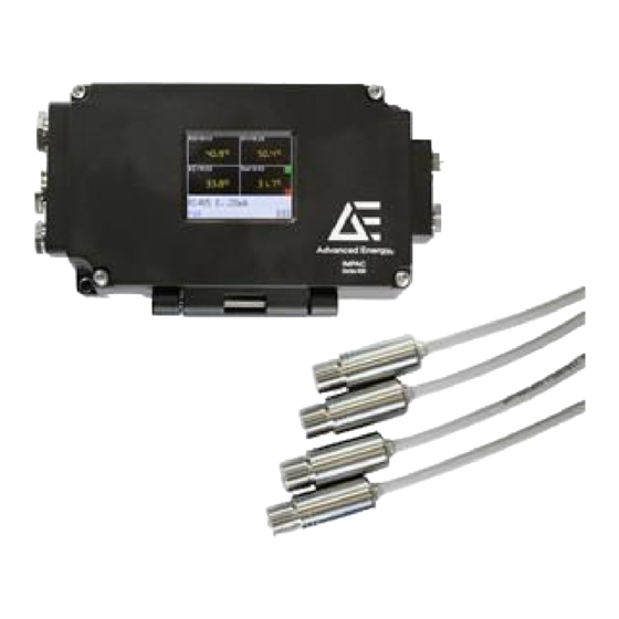
- Page 1 ® Impac Series 600 Pyrometer User Manual 57010228-00C May 2022 ...
- Page 2 Industries, Inc. All Rights Reserved. DISCLAIMER AND LIMITATION OF LIABILITY The information contained in this manual is subject to change by Advanced Energy Industries, Inc. without prior notice. Advanced Energy Industries, Inc. makes no warranty of any kind whatsoever, either expressed or implied, with respect to the information contained herein.
- Page 3 All other trademarks are the property of their respective owners. CUSTOMER FEEDBACK Advanced Energy’s technical writing staff has carefully developed this manual using research-based document design principles. However, improvement is ongoing, and the writing staff welcomes and appreciates customer feedback. Please send any comments on the content, organization, or format of this user manual to: •...
-
Page 4: Table Of Contents
® ® Advanced Energy Impac Series 600 Pyrometer Table of Contents Chapter 1. Safety and Product Compliance Guidelines Important Safety Information ................. 1-1 Danger, Warning, and Caution Boxes .............. 1-1 Safety Guidelines .................... 1-1 Rules for Safe Installation and Operation ............ 1-2 Interpreting Product Labels ................ - Page 5 ® ® Advanced Energy Impac Series 600 Pyrometer Grounding the Pyrometer ................ 3-3 Connecting the Sensor Cable ................. 3-3 Connecting the Sensor Head ................. 3-4 Connecting Input Power to the Unit .............. 3-5 Connecting Serial Communications ............... 3-6 Baud Rate .................... 3-6 Cable Length .................... 3-7...
- Page 6 ® ® Advanced Energy Impac Series 600 Pyrometer Appendix B. Unit Specifications Physical Specifications .................. B-1 Temperature Measurement Specifications ............ B-2 Electrical Specifications .................. B-4 Cooling Specifications .................. B-5 Environmental Specifications ................ B-5 Appendix C. Spot Size Specifications ...
- Page 7 ® ® Advanced Energy Impac Series 600 Pyrometer List of Tables Table 2-1. Sensor head connector pin assignments (male) ........ 2-3 Table 2-2. Sensor cable connector pin assignments (female) ...... 2-4 Table 3-1. Soft key functions ................ 3-15 Table 3-2. Clear time interval settings .............. 3-20 Table 4-1.
- Page 8 ® ® Advanced Energy Impac Series 600 Pyrometer List of Figures Figure 2-1. Standard sensor head connector (male) .......... 2-3 Figure 2-2. Extension cable connectors .............. 2-4 Figure 2-3. Sensor cable connector (female) ............ 2-4 Figure 2-4. Converter box connectors .............. 2-5 Figure 2-5. Single-analog box connectors ............ 2-6 Figure 2-6.
-
Page 9: Chapter 1. Safety And Product Compliance Guidelines
Guidelines IMPORTANT SAFETY INFORMATION To ensure safe installation and operation of the Advanced Energy Impac unit, read and understand this manual before attempting to install and operate this unit. At a minimum, read and follow the safety guidelines, instructions, and practices. -
Page 10: Rules For Safe Installation And Operation
® ® Advanced Energy Impac Series 600 Pyrometer Rules for Safe Installation and Operation Please note the following rules: • Ensure that this unit is properly grounded. • Ensure that all cables are properly connected. • Verify that input voltage and current source capacity are within specifications before turning on the unit. -
Page 11: Product Compliance
® ® Advanced Energy Impac Series 600 Pyrometer PRODUCT COMPLIANCE The following sections include information about unit compliance and certification, including the conditions of use required to be in compliance with the standards and directives. Product Certification Certain options of this product may be certified according to the list below. -
Page 12: Environmental Compliance
• Do not allow condensation of any liquids or accumulation of conductive dust on the instrument. Doing so will have unpredictable results, possibly including, but not limited to, loss of accuracy. • Advanced Energy requires that AE-trained personnel perform all maintenance and service on the unit. Environmental Compliance •... -
Page 13: Chapter 2. Product Overview
® Impac Series 600 Pyrometer Chapter Product Overview GENERAL DESCRIPTION All substances with a temperature above absolute zero emit radiant energy. Thermal radiation increases with an increase in temperature. An optical pyrometer measures the radiation at a given wavelength, and from that radiant flux, calculates the absolute temperature of the target. -
Page 14: Sensor Cables
® ® Advanced Energy Impac Series 600 Pyrometer Sensor heads are attached to a 300 mm (11.8″) cable with a male connector on the end for connecting them to a sensor cable or extension cable. The only exception are the high temperature sensor heads, which have an additional 3 m (9′10″) cable attached behind the sensor head to separate the electronics. -
Page 15: Unit Connectors
® ® Advanced Energy Impac Series 600 Pyrometer UNIT CONNECTORS Depending on the setup for your application, the pyrometer might use one or several of the following connectors. Sensor Head Connectors Sensor heads connect to a sensor cable or an extension cable using a 3-pin connector (male) as shown in the following figure. -
Page 16: Sensor Cable Connectors
® ® Advanced Energy Impac Series 600 Pyrometer Figure 2‑2. Extension cable connectors Sensor Cable Connectors Sensor cables for connecting a sensor head or an extension cable to a converter box, multi-sensor box, or analog box have one 3-pin connector (female) as shown in the following figure. -
Page 17: Converter Box Connectors
® ® Advanced Energy Impac Series 600 Pyrometer Table 2‑2. Sensor cable connector pin assignments (female) (Continued) Wire Color Black Brown Converter Box Connectors Wires for each connection to the converter box must be terminated and connected individually to the appropriate pins in the terminal blocks as shown in the following figure. -
Page 18: Multi-Sensor Box Connectors
® ® Advanced Energy Impac Series 600 Pyrometer Relay contact, analog output, power supply Sensor head Micro USB Figure 2‑5. Single-analog box connectors Relay contacts and power supply Analog outputs Sensor heads Micro USB Figure 2‑6. Multi-analog box connectors Multi-Sensor Box Connectors... -
Page 19: Software
® ® Advanced Energy Impac Series 600 Pyrometer Sensor heads Converter box Figure 2‑7. Multi-sensor box connectors SOFTWARE Though your pyrometer will work without software, you must use the Infra600 software if you want to connect it to a PC and perform certain tasks (for example, adjusting the parameters, visualizing the temperature measurements, or analyzing the data). -
Page 20: Chapter 3. Installation, Setup, And Operation
® Impac Series 600 Pyrometer Chapter Installation, Setup, and Operation PREPARING TO INSTALL THE UNIT Unpacking the Unit ☞ Important The labels on the packaging provide important safety and handling information. Follow your company procedures when unpacking the unit. 1. -
Page 21: Installing The Unit
® ® Advanced Energy Impac Series 600 Pyrometer Measuring distance Figure 3‑1. Spot size from any measuring distance (ratio) For the approximate distance ratio of your pyrometer and some example spot sizes, Appendix C, “Spot Size Specifications”. INSTALLING THE UNIT Mounting the Pyrometer Your pyrometer will work with or without mounting. -
Page 22: Grounding The Pyrometer
® ® Advanced Energy Impac Series 600 Pyrometer Grounding the Pyrometer If you are using a converter box, make a suitable earth ground connection using a customer-supplied ground cable as shown in the following figure. This will prevent transmission interference. -
Page 23: Connecting The Sensor Head
® ® Advanced Energy Impac Series 600 Pyrometer TO CONNECT THE SENSOR CABLE 1. Open the feedthrough by removing the clamp screw, washer, and O-ring from the feedthrough. 2. Feed the cable through the clamp screw, washer, and O-ring. 3. Slide the cable wires and end sleeves into the feedthrough, and then connect the wires to the terminal block (corresponding to marked colors). -
Page 24: Connecting Input Power To The Unit
® ® Advanced Energy Impac Series 600 Pyrometer 3. Discover (identify) the newly connected sensor head in one of the following ways. ◦ If using a converter box with a display, select DIS. ◦ In the Infra600 software, click Discover. -
Page 25: Connecting Serial Communications
® ® Advanced Energy Impac Series 600 Pyrometer TO CONNECT INPUT POWER TO THE UNIT 1. Connect input power to the converter box or analog box in one of the following ways. ◦ Connect the converter box or analog box to a power supply using the provided cable, ensuring correct polarity. -
Page 26: Cable Length
® ® Advanced Energy Impac Series 600 Pyrometer CABLE LENGTH The maximum cable length is determined by the serial communication being used and the baud rate. • Maximum cable length for RS-232 at 19200 baud is 7 m (23′). • Maximum cable length for RS-485 at 19200 baud is 2 km (6561′8″). -
Page 27: Connecting To Profinet
® ® Advanced Energy Impac Series 600 Pyrometer Use either a connection cable from AE or use a customer-supplied cable to connect directly to the terminal block on the converter box. To Connect to an RS-485 Interface 1. Connect the A1 wire to pin 3 (DIG 3). -
Page 28: Connecting To Usb
® ® Advanced Energy Impac Series 600 Pyrometer ◦ If LED 3 is off, there is no bus connection. ◦ If LED 3 is solid green (constant), a bus connection, functioning network, and Ethernet-link-impulses are found, but there is no activity. -
Page 29: First Time Operation
® ® Advanced Energy Impac Series 600 Pyrometer Route two separate ground wires in the cable: one ground wire for the voltage signals and one ground wire for the current signals. Both ground wires need to be connected to the ground clamp of the multi-analog box. -
Page 30: Setting The Converter Box Address
® ® Advanced Energy Impac Series 600 Pyrometer TO INSTALL THE INFRA600 SOFTWARE 1. Locate and extract the Infra600 .zip file. 2. Run the .exe file and follow the on-screen instructions to install the Infra600 software. Setting the Converter Box Address... -
Page 31: Setting The Sensor Head Address
® ® Advanced Energy Impac Series 600 Pyrometer Related Links • “Parameterizing Devices Using the Converter Box Display” on page 3‑15 Setting the Sensor Head Address When you connect sensor heads to a converter box, the converter box will automatically assign each sensor head a number (from 1 to 8) based on the order in which the converter box detects the sensor heads. -
Page 32: Normal Operation
® ® Advanced Energy Impac Series 600 Pyrometer NORMAL OPERATION The Impac pyrometer will only get a correct temperature reading when the emissivity settings are correct for the target material, the pyrometer is aligned to the target object, the spot size is smaller than the target object, the ambient conditions are stable, and there are no other disturbances (such as reflections). - Page 33 ® ® Advanced Energy Impac Series 600 Pyrometer • The data exchange for these commands is in ASCII format <AA>xx<VAL> <CR> (for the converter box commands) or <AAXn>xx<VAL> <CR> (for sensor head commands), where: ◦ <AA> is the two-character converter box address ◦...
-
Page 34: Parameterizing Devices Using The Converter Box Display
® ® Advanced Energy Impac Series 600 Pyrometer addition to the command name, the analog out, "sX", has to be added. X can range from 1 to 8. For example, to set analog output signal for analog out 1, the command would be: ... -
Page 35: Parameterization Flowchart
® ® Advanced Energy Impac Series 600 Pyrometer Table 3‑1. Soft key functions (Continued) Soft Keys Description Down arrow • Toggles devices for selection • Decreases a parameter value DIS or ESC • Detects newly connected sensor heads • Returns to the previous screen When changing settings with the converter box display, you first must make a selection from the available devices to be parameterized. -
Page 36: Figure 3-6. Parameterization Process Flowchart
® ® Advanced Energy Impac Series 600 Pyrometer ☞ Important Pressing ESC at any time during the parameterization process will cancel the current step and go back to the previous step. Press PAR Displays device No, change device Desired device? Press ↑... -
Page 37: Exposure Time
® ® Advanced Energy Impac Series 600 Pyrometer Exposure Time The exposure time (t ) is the time interval for the output of the pyrometer to go from the lowest value in its measuring range up to 90% of the highest value in its... -
Page 38: Clear Time Interval For The Maximum Value Storage
® ® Advanced Energy Impac Series 600 Pyrometer Additional methods for determining the emissivity of your target object include the following: • Emissivity tables (see Appendix G, “Emissivity of Common Materials”) • Measurement in a blind hole (6x diameter) • Measurement at the melting point of the material •... -
Page 39: Wait Time
® ® Advanced Energy Impac Series 600 Pyrometer Table 3‑2. Clear time interval settings Setting Description This setting switches off the maximum value storage; temperatures are measured in real time. 0.1 s to With this setting, the maximum value storage operates in double storage 25 s mode. -
Page 40: Limit Switch
® ® Advanced Energy Impac Series 600 Pyrometer ☞ Important The internal temperature of the converter box and sensor heads should always be within the ambient temperature range specifications. See Appendix B, “Unit Specifications”. Limit Switch Your converter box is equipped with a relay contact controlled by the measuring signal. -
Page 41: Periodic Calibration
Damage to the lens can dramatically affect measurement accuracy. Using a damaged pyrometer will negatively impact the measurement accuracy. If the pyrometer is physically damaged, return the pyrometer to Advanced Energy for repair and recalibration or replacement. See “Service, Repairs, and Upgrades”. -
Page 42: Chapter 4. Troubleshooting And Technical Support Organization
® Impac Series 600 Pyrometer Chapter Troubleshooting and Technical Support Organization Before requesting support, perform the recommended checks and the troubleshooting procedures in this chapter. If you are still unable to resolve the issue and resume normal operation of the equipment, contact Technical Support Organization. You can find the contact information for “Technical Support Organization”... - Page 43 ® ® Advanced Energy Impac Series 600 Pyrometer Table 4‑1. Troubleshooting checklist (Continued) Symptom Probable Cause and Remedy Target object is not always in the measuring spot of the pyrometer • Use maximum value storage and clear time intervals to apply settings for automatically adjusting the temperature readings based on the stored maximum value.
-
Page 44: Technical Support Organization
• Use a ratio pyrometer. TECHNICAL SUPPORT ORGANIZATION For help using or troubleshooting products, contact the Advanced Energy Technical Support Organization Organization (TSO). Proceed as follows: 1. Make a note of the serial number (SN) and part number (PN) listed on the product label. - Page 45 4. Complete and submit the RMA form. Obtaining an RMA Number Using the Online Form To obtain an RMA number using the online form on the Advanced Energy web page, proceed as follows: 1. Make a note of the serial number (SN) and part number (PN) listed on the product label.
- Page 46 ® ® Advanced Energy Impac Series 600 Pyrometer 1. Make a note of the serial number (SN) and part number (PN) listed on the product label. 2. Address an email to mailto:technical.support@aei.com. 3. In the subject line of the email, mention that you are requesting an RMA and include the product serial number (SN) found on the product label.
-
Page 47: Appendix A. Unit Dimensional Drawings
® Impac Series 600 Pyrometer Appendix Unit Dimensional Drawings The following figures show the possible dimensions for the Impac pyrometer. Figure A‑1. Sensor head dimensions with sensor cable Figure A‑2. High temperature sensor head dimensions with sensor cable Figure A‑3. Sensor head dimensions with sensor cable to USB 57010228-00C Unit Dimensional Drawings A‑1... -
Page 48: Figure A-4. Converter Box And Multi-Analog Box Dimensions
® ® Advanced Energy Impac Series 600 Pyrometer Figure A‑4. Converter box and multi-analog box dimensions 57010228-00C Unit Dimensional Drawings A‑2... -
Page 49: Figure A-5. Single-Analog Box Dimensions
® ® Advanced Energy Impac Series 600 Pyrometer Figure A‑5. Single-Analog box dimensions 57010228-00C Unit Dimensional Drawings A‑3... -
Page 50: Figure A-6. Multi-Sensor Box Dimensions
® ® Advanced Energy Impac Series 600 Pyrometer Figure A‑6. Multi-sensor box dimensions 57010228-00C Unit Dimensional Drawings A‑4... -
Page 51: Appendix B. Unit Specifications
® Impac Series 600 Pyrometer Appendix Unit Specifications PHYSICAL SPECIFICATIONS Table B‑1. Physical specifications Description Specification Size Appendix A, “Unit Dimensional Drawings” Weight Sensor heads: 40 g (1.4 oz) Converter box with display: 395 g (13.9 oz) Converter box without display: 380 g (13.4 oz) Multi-sensor box: 260 g (9.2 oz) Analog box with one connection: 300 g (10.6 oz) Analog box with two connections: 400 g (14.1 oz) -
Page 52: Temperature Measurement Specifications
® ® Advanced Energy Impac Series 600 Pyrometer TEMPERATURE MEASUREMENT SPECIFICATIONS Table B‑2. Temperature measurement specifications Description Specification Temperature measurement IN 600: ranges −40°C to 700°C (−40°F to 1292°F) (MB 7) IS 600: 500°C to 1400°C (932°F to 2552°F) (MB 14) ... - Page 53 ® ® Advanced Energy Impac Series 600 Pyrometer Table B‑2. Temperature measurement specifications (Continued) Description Specification Output impedance 18 Ω (for thermocouple or voltage output) Analog output • Analog output converter boxes (selectable): Current (0 mA to 20 mA or 4 mA to 20 mA, linear), voltage (0 V to 5 V), or thermocouple (type J or type K) •...
-
Page 54: Electrical Specifications
® ® Advanced Energy Impac Series 600 Pyrometer Table B‑2. Temperature measurement specifications (Continued) Description Specification of uncertainty: 0.03% per °C or 0.05°C per °C at 25°C ambient temperature (T ), whichever value is greater. The pyrometer must be at a constant ambient temperature for a minimum of 15 minutes. -
Page 55: Cooling Specifications
® ® Advanced Energy Impac Series 600 Pyrometer Table B‑3. Electrical specifications (Continued) Description Specification Warm-up delay 5 minutes COOLING SPECIFICATIONS Refer to the following air cooling specifications when using the air purge accessories with the Impac pyrometer. Table B‑4. Air cooling specifications... - Page 56 ® ® Advanced Energy Impac Series 600 Pyrometer Table B‑6. Climatic specifications (Continued) Description Specification 0°C to 70°C (32°F to 158°F) on housing Multi-analog box: 0°C to 60°C (32°F to 140°F) on housing Storage temperature Converter box and multi-analog box: ...
-
Page 57: Appendix C. Spot Size Specifications
® Impac Series 600 Pyrometer Appendix Spot Size Specifications IN 600 AND IN 600/5 PYROMETER SPOT SIZES Table C‑1. Optics 1N (2:1), −40°C to 700°C (−40°F to 1292°F) (MB 7) Measuring Distance Spot Size Distance Ratio/FOV 4 mm (0.2″) 100 mm (3.9″) 43 mm (1.7″) 200 mm (7.9″) -
Page 58: Is 600 Pyrometer Spot Sizes
® ® Advanced Energy Impac Series 600 Pyrometer Table C‑3. Optics 3N (20:1), −40°C to 700°C (−40°F to 1292°F) (MB 7) (Continued) Measuring Distance Spot Size Distance Ratio/FOV 1000 mm (39.4″) 56 mm (2.2″) 2000 mm (78.7″) 115 mm (4.5″) 17.4... -
Page 59: Appendix D. Factory Settings
® Impac Series 600 Pyrometer Appendix Factory Settings Table D‑1. Default factory settings Specification Setting Emissivity (ε) 100% Response time (t Minimum Analog output 0 mA to 20 mA Baud rate 19200 baud Address (converter box) Wait time (t ) (for RS-485 only) At the default baud rate of 115200 baud, this means a wait time of 10/115200 seconds. -
Page 60: Appendix E. Pyrometer Parameters (Converter Box With Display)
® Impac Series 600 Pyrometer Appendix Pyrometer Parameters (Converter Box with Display) Table E‑1. Converter box parameters Parameter Description M/ADR Address (device address, 00 to 97) ADDR Automatic addressing • Reset all: Each sensor head will be set back to factory setting (address 00) •... -
Page 61: Table E-2. Sensor Head Parameters
® ® Advanced Energy Impac Series 600 Pyrometer Table E‑1. Converter box parameters (Continued) Parameter Description RS/tw Wait time for RS-485 T/REP ON FAIL Defines how often a request to a sensor head is repeated (in case of no response or a wrong answer) before an error message is shown (timeout) Table E‑2. -
Page 62: Appendix F. Upp Commands
® Impac Series 600 Pyrometer Appendix UPP Commands Table F‑1. Sensor head UPP commands Parameter Command Description Read measuring <AAXn>ms Reports the most recent temperature value measurement read by the sensor head. The pyrometer responds with a 5-digit value in °C or °F, rounded to one decimal place. -
Page 63: Table F-1. Sensor Head Upp Commands
® ® Advanced Energy Impac Series 600 Pyrometer Table F‑1. Sensor head UPP commands (Continued) Parameter Command Description YYYY = End of the temperature range Example: 028A0708 = 650° to 1800° Read <AAXn>me Reports the currently set temperature temperature measurement subrange for the sensor head. - Page 64 ® ® Advanced Energy Impac Series 600 Pyrometer Table F‑1. Sensor head UPP commands (Continued) Parameter Command Description 6 = 30 s Valid values for IS 600, IGA 600, and IGA 600/23: 0 = Intrinsic time constant of the unit (10 ms) ...
-
Page 65: Table F-2. Converter Box And Analog Box Upp Commands
® ® Advanced Energy Impac Series 600 Pyrometer Table F‑1. Sensor head UPP commands (Continued) Parameter Command Description Read internal <AAXn>gt Reports the internal temperature of the sensor sensor head head. temperature Response in °C: 4-digit value from 0000 to 1800 Response in °F: 4-digit value from 0320 to 3560... - Page 66 ® ® Advanced Energy Impac Series 600 Pyrometer Table F‑2. Converter box and analog box UPP commands (Continued) Parameter Command Description Sensor head for <AA>ax<VAL> Sets the sensor head that will be used for analog analog output output of the converter box.
- Page 67 ® ® Advanced Energy Impac Series 600 Pyrometer Table F‑2. Converter box and analog box UPP commands (Continued) Parameter Command Description Wait time (t <AA>tw<VAL> Sets the wait time for the converter box. The set value represents a fraction in relation to the selected baud rate.
- Page 68 ® ® Advanced Energy Impac Series 600 Pyrometer Table F‑2. Converter box and analog box UPP commands (Continued) Parameter Command Description Valid values are 0 to 3. 0 = Keys are not locked 1 = Enable keys lock; you can disable keys...
- Page 69 ® ® Advanced Energy Impac Series 600 Pyrometer Table F‑2. Converter box and analog box UPP commands (Continued) Parameter Command Description Switch contact <AA>s1<VAL> Sets the threshold temperature for the switch threshold contact on the converter box. The set value For analog box with...
- Page 70 ® ® Advanced Energy Impac Series 600 Pyrometer Table F‑2. Converter box and analog box UPP commands (Continued) Parameter Command Description The converter box responds with a 2-digit value from 00 to 08 identifying the number of sensor heads connected. Display <AA>ro<VAL>...
- Page 71 ® ® Advanced Energy Impac Series 600 Pyrometer Table F‑2. Converter box and analog box UPP commands (Continued) Parameter Command Description Change IP <AA>ip<VAL> 8-digit hexadecimal ASCII. Use the re address of command to restart the pyrometer and activate PROFINET the new address.
-
Page 72: Table G-1. Emissivities For Spectral Range: 0.7 Μm To 1.1 Μm
® Impac Series 600 Pyrometer Appendix Emissivity of Common Materials ☞ Important Emissivity tables only provide approximate values. Actual emissivity values will always vary depending on the measuring conditions, and should be calculated using other methods. Table G‑1. Emissivities for spectral range: 0.7 μm to 1.1 μm Target Object Material Emissivity (%) Aluminum, bright... -
Page 73: Table G-3. Emissivities For Spectral Range: 2 Μm To 2.6 Μm
® ® Advanced Energy Impac Series 600 Pyrometer Table G‑2. Emissivities for spectral range: 1.45 μm to 1.8 μm (Continued) Target Object Material Emissivity (%) Blackbody furnace Brass, oxidized (tarnished) 60 to 70 Brick 80 to 90 Bronze, bright Chamotte 45 to 60... -
Page 74: Table G-4. Emissivities For Spectral Range: 8 Μm To 14 Μm
® ® Advanced Energy Impac Series 600 Pyrometer Table G‑3. Emissivities for spectral range: 2 μm to 2.6 μm (Continued) Target Object Material Emissivity (%) Molybdenum Molybdenum, oxidized 75 to 80 Nickel 15 to 20 Porcelain, rough 80 to 90 Steel, molten... - Page 75 ® ® Advanced Energy Impac Series 600 Pyrometer Table G‑4. Emissivities for spectral range: 8 μm to 14 μm (Continued) Target Object Material Emissivity (%) Water Wood 80 to 92 57010228-00C Emissivity of Common Materials G‑4...
-
Page 76: Appendix H. Wiring Diagrams For Multiple Analog Outputs
® Impac Series 600 Pyrometer Appendix Wiring Diagrams for Multiple Analog Outputs POSSIBLE WIRING FOR DIFFERENTIAL VOLTAGE INPUTS In many cases, differential voltage inputs exist. Figure H‑1 shows the wiring using a multi-core cable with a 7 Ω resistance per wire (for example, 7 Ω corresponds to ²... -
Page 77: Possible Wiring For Simple, Non-Differential Voltage Inputs
® ® Advanced Energy Impac Series 600 Pyrometer Multi-Analog Box Analog Outputs Analog Inputs Output 1 +Input 1 −Input 1 Input 2 Output 2 Input 3 Output 3 Input 4 Output 4 Input 5 Output 5 Input 6 Output 6... -
Page 78: Possible Wiring For Galvanically Separated Analog Inputs
® ® Advanced Energy Impac Series 600 Pyrometer Multi-Analog Box Analog Outputs Analog Inputs Output 1 Input 1 Input 0 Input 2 Output 2 Input 3 Output 3 Input 4 Output 4 Input 5 Output 5 Input 6 Output 6... -
Page 79: Figure H-3. Wiring Example For Galvanically Separated Input Modules
® ® Advanced Energy Impac Series 600 Pyrometer Multi-Analog Box Analog Outputs Analog Inputs Output 1 Input 1 Input 2 Output 2 Input 3 Output 3 Input 4 Output 4 Common Input 5 Output 5 Input 6 Output 6 Input 7... - Page 80 ® ® Advanced Energy Impac Series 600 Pyrometer Index emissivity table G‑1 3-pin connector 2‑3 exposure time 3‑18 external window, optional 3‑1 additional devices connecting 3‑9 factory settings D‑1 analog box connectors 2‑3 flowchart, parameterization 3‑16 authorized returns 4‑3 grounding 3‑3...
- Page 81 ® ® Advanced Energy Impac Series 600 Pyrometer maximum value storage 3‑19 specifications B‑1 mounting the pyrometer 3‑2 spot sizes 3‑1 multiple analog outputs 3‑9 temperature display 3‑20 multi-sensor box connectors 2‑3 troubleshooting 4‑1 normal operation 3‑13 refurbishment schedule 3‑22 clear time interval 3‑19...
- Page 82 ® ® Advanced Energy Impac Series 600 Pyrometer wiring diagrams H‑1 galvanically separated analog inputs H‑3 wait time 3‑20 non-differential voltage inputs H‑2 warranty authorized returns 4‑3 wiring diagram differential voltage inputs H‑1 57010228-00C Index...
Need help?
Do you have a question about the Impac 600 Series and is the answer not in the manual?
Questions and answers