Table of Contents
Advertisement
Quick Links
Advertisement
Table of Contents

Related Manuals for Advanced Energy LumaSense Technologies E2T QUASAR Series


Summary of Contents for Advanced Energy LumaSense Technologies E2T QUASAR Series
- Page 1 T QUASAR Flare Monitors M8100PM-EXP • M8100FM-EXP • M8100SM-EXP...
- Page 2 Confidential Information The material contained herein consists of information that is the property of LumaSense Technologies, an Advanced Energy Company, and intended solely for use by the purchaser of the equipment described in this manual. All specifications are subject to change without notice. Changes are made periodically to the information in this publication, and these changes will be incorporated in new editions.
-
Page 3: Table Of Contents
Contents General ..........................7 1.1 Information about the user manual ..............7 1.1.1 Legend ........................7 1.2 Safety ........................7 1.2.1 Explosion Proof Housing ..................8 1.3 Limit of Liability and Warranty ................8 1.4 Unpacking and Inspection ..................8 1.5 Service Request, Repair, or Support .............. - Page 4 4.2 Power Connections ....................23 4.2.1 Service Markings ....................23 4.2.2 Protective Ground Connection ................24 4.2.3 Cover Attachment ....................24 4.2.4 Powering with 115 Volts AC∽ ................25 4.2.5 Powering with 220/230 Volts AC∽ ................ 25 4.2.6 Powering with 24 Volts DC ................
- Page 5 Troubleshooting ......................47 8.1 Problem Isolation Checkout Procedure ............... 47 8.1.1 Sight Path and Optical Alignment ................ 47 8.1.2 Power Input ......................47 8.1.3 Power Fuse ......................47 8.1.4 Instrument Loops ....................47 8.1.5 Stopped Chopper Wheel ..................48 8.1.6 Broken Wire Harness .....................
- Page 6 To ensure consistent document formatting, this page was intentionally left blank. T QUASAR Flare Monitors Operation Manual General • vi...
-
Page 7: General
1 General 1.1 Information about the user manual This manual provides important information that can be used as a work of reference for installing, operating, maintaining, aligning, and/or troubleshooting your LumaSense Instrument. It is important that you carefully read the information contained in this manual and follow all safety procedures before you install or operate the system. -
Page 8: Explosion Proof Housing
1.2.1 Explosion Proof Housing The housing is designed to meet the explosion-proof requirements of the National Fire Protection Association (NFPA) Article 500 for hazardous locations. This Instrument holds both CSA International and European (ATEX) certifications. To ensure safe operating conditions, it is recommended that you review the certification and area classifications that pertain to this system: Reference •... -
Page 9: Service Request, Repair, Or Support
When unpacking and inspecting your system, you need to do the following: • Check all materials in the container against the enclosed packing list. • LumaSense Technologies cannot be responsible for shortages against the packing list unless a claim is immediately filed with the carrier. Final claim and negotiations with the carrier must be completed by the customer. -
Page 10: Shipments To Lumasense For Repair
1.6 Shipments to LumaSense for Repair All RMA shipments of LumaSense Technologies instruments are to be prepaid and insured by way of preferred carrier. For overseas customers, ship units air-freight, priority one. The instrument must be shipped in the original packing container or its equivalent. LumaSense Technologies is not responsible for freight damage to instruments that are improperly packed. -
Page 11: Introduction
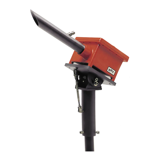
2 Introduction 2.1 System Overview The Quasar 8100-EXP Pilot Monitor (PM), Flare Monitor (FM), and Smoke Monitor (SM) are unique monitoring and detection instruments designed for continuous duty monitoring of Pilot Flame, Flaring and Smoke on Flares. The heart of the LumaSense E T QUASAR M8100-EXP Flare Monitoring System is the non-contact infrared Electro-Optical package, which can be removed from the explosion proof housing for repairs or replacement, while leaving all wiring and alignment of the system intact... -
Page 12: System Features
A sight-through optical system and selection of various optical resolutions (fields of view) enable the QUASAR M8100-EXP to be positioned as far as 1/4 mile (400 m) from the stack being monitored. Alignment on the target is accomplished using exceptional sight-through optics and the M-3 Heavy Duty Swivel Mount. -
Page 13: Principle Of Operation
2.3 Principle of Operation All objects above absolute zero emit infrared energy. The amount of energy emitted is proportional to the body’s temperature. The QUASAR M8100-EXP collects this energy by means of a focusing optical system concentrating the energy from a body onto a sensitive infrared detector. -
Page 14: Pm: Pilot Monitor's Flame Sensitive Wavelength
2.4.2 PM: Pilot Monitor’s Flame Sensitive Wavelength The QUASAR M8100PM-EXP uses a single select filter allowing the electronics to amplify the IR energy of interests over the background IR energy. This allows the Pilot Monitor to achieve high sensitivity and dynamic range. 2.4.3 FM: Flare Monitor’s Flame Sensitive Wavelength The QUASAR M8100FM-EXP uses a single select filter allowing the electronics to amplify the IR... - Page 15 Note: Secure power input lines together after connection to the Terminal block to prevent an accidental hazardous live condition in the unlikely event that a terminal screw becomes loose. Sleeve or tie wrapping is acceptable. b. Connect the instrument loops and alarm outputs: i.
- Page 16 To ensure consistent document formatting, this page was intentionally left blank. T QUASAR Flare Monitors Operation Manual Introduction • 16...
-
Page 17: Mechanical Installation
3 Mechanical Installation 3.1 Getting Started Each LumaSense E T QUASAR M8100-EXP instrument is configured as per customer’s request. The packing slip order number matches that of the instrument’s serial number. It is recommended to confirm that the instrument’s configuration meets expectation, by reviewing packing slip details. -
Page 18: Flare Monitor (Fm) Sighting
Figure 4: Field of View Concept 3.2.2 Flare Monitor (FM) Sighting Recommended installation distance should be equal to the height of the flare stack from the base of the flare stack. The maximum vertical angle for sighting the monitor is 45 ° above horizontal. -
Page 19: Ambient Temperature Limits
Figure 5: Pedestal Mounting Concept 3.3 Ambient Temperature Limits The ambient operating temperature limits of the QUASAR M8100-EXP are -40 °F (-40 °C) to 120 °F (50 °C). When the internal temperature drops below 40 °F (4 °C), an internal electric heater activates to keep the internal temperature at or above 40 °F (4 °C). -
Page 20: Vortex Air Cooling
Note: The cooling cavity is isolated from internal surface of explosion-proof enclosure. See Appendix E Engineering Drawing 613-816, Service Connections. 3.4.2 Vortex Air Cooling Connect a V208-15-H Vortex Air cooler to the cooling cavity built into the underside of the explosion-proof enclosure. - Page 21 (1) Eyepiece Lens with Reticle (2) Focus Adjust and Lens Locking Screw (3) Objective Lens T QUASAR Flare Monitors Operation Manual Mechanical Installation • 21...
- Page 22 To ensure consistent document formatting, this page was intentionally left blank. T QUASAR Flare Monitors Operation Manual Mechanical Installation • 22...
-
Page 23: Electrical Installation
4 Electrical Installation 4.1 Electrical Installation Guidelines Be sure to reference Appendix E Engineering Drawing 613-816, Service Connections during this procedure. 4.1.1 Conduit/Connections Power and signal wires are fed through the 3/4 inch NPT conduit holes in the side of the housing. -
Page 24: Protective Ground Connection
4.2.2 Protective Ground Connection Connect the protective Earth conductor to the terminal lug located inside the housing as indicated by the symbol. 4.2.3 Cover Attachment Warning: At no time should the cover be removed unless power is switched off first. When it is necessary to service the instrument with the power applied, ensure that proper safe environmental conditions exist and that such maintenance is authorized and pursuant to safe conditions. -
Page 25: Powering With 115 Volts Ac
4.2.4 Powering with 115 Volts AC∽ Note: Voltage/fusing are factory set. Use a wire gauge appropriate to service installation. See Appendix A for Power and Fuse Requirements and Appendix E Engineering Drawing 613-816, Service Connections. To connect 115 VAC to Terminal TB1: •... -
Page 26: Fusing
4.3 Fusing 4.3.1 Mains Two fuses, F1 and F2, are each mounted within fuse holders on the Terminal Output PC Board, located directly under TB1. • F1 is used for all power configurations. • F2 is used only in 220 / 230 V AC applications. Note: The factory installed F2 bypass jumper J1, is hardwired for 110 V AC and 24 V DC systems. -
Page 27: Connecting The Set Point Relay
4.5 Connecting the Set Point Relay The set point relay provides a dry contact closure with a normally open and normally closed output. The relay is rated 1 amp resistive to 120 V AC max. Connect the relay to terminal TB2 as follows: •... - Page 28 To ensure consistent document formatting, this page was intentionally left blank. T QUASAR Flare Monitors Operation Manual Electrical Installation • 28...
-
Page 29: Operating The M8100Pm-Exp
5 Operating the M8100PM-EXP This section covers the start-up procedures for operating the flare stack Pilot Monitor after the unit has been installed in accordance with Chapters 3 and Chapter 4. To provide insight into the logic behind the procedure, some background on the field operation of the instrument is provided. - Page 30 Figure 7: Instrument Aiming Concept T QUASAR Flare Monitors Operation Manual Operating the M8100PM-EXP • 30...
-
Page 31: Start-Up Operation Checklist, Pilot Monitor (Pm)
1. Eyepiece Lens with Reticle Status Red LED: Alarm Status Green LED AGC Compensation (PM) System Gain Adjust Gain/Setpoint Selector Focus Adjust and Lens Locking Screw Objective Lens Delay Adjust Set-Point Adjust Gain/Setpoint Monitor Heater Connection . Output PCB Main Supply Connector to Electronics Signal I/O to Electronics Figure 8: Opto-Electronics Module... -
Page 32: Initial Control Settings
5.1.2 Initial Control Settings (Item numbers refer to and Figure 9: Opto-Electronics Module) 1. Adjust all Pots to full counterclockwise (Items: 5, 9, 10). 2. Set Climatic Compensation Selector Switch (Item 4) at 100X. 3. Move the Gain/Setpoint Switch (Item 6) to Setpoint position. 4. -
Page 33: Noise Amplification
5.1.6 Noise Amplification Once setup adjustments have been completed, confirm that the flame signal, and not the noise, is being amplified. Check for noise application. To check for Noise Amplification: 1. Completely cover the objective lens. 2. Ensure that the red LED activates with the anticipated delay time. If the red LED fails to activate or there is repeated green-red-green-red “chatter,”... -
Page 34: Delay Adjust
5.1.8 Delay Adjust The Delay Adjust (Figure 9, Item 9) can be configured from 2 seconds (completely counterclockwise) to approximately 2 minutes (completely clockwise). The Delay Pot postpones the Alarm condition once the set-point value is exceeded. This can prevent false alarms from temporary loss of signal due to wind. -
Page 35: Operating The M8100Fm-Exp
6 Operating the M8100FM-EXP This section covers the start-up procedures for operating the flare stack Flare Monitor after the unit has been installed in accordance with Chapters 3 and Chapter 4. To provide insight into the logic behind the procedure, some background on the field operation of the instrument is provided. -
Page 36: Start-Up Operation Checklist, Flare Monitor (Fm)
1. Eyepiece Lens with Reticle Status Red LED : Alarm Status Green LED AGC Compensation (PM) System Gain Adjust Gain/Setpoint Selector Focus Adjust and Lens Locking Screw Objective Lens Delay Adjust Set-Point Adjust Gain/Setpoint Monitor Heater Connection Output PCB Main Supply Connector to Electronics . -
Page 37: Initial Control Settings
6.1.2 Initial Control Settings (Item numbers refer to and Figure 11: Opto-Electronics Module) 1. Adjust all Pots to full counterclockwise (Items: 5, 9, 10). 2. Set the Climatic Compensation Selector Switch (Item 4) at 100X. 3. Move the Gain/Setpoint Switch (Item 6) to Setpoint position. 4. -
Page 38: Noise Amplification
the Pilot flame when the Flare is not present. Complete the procedure below and be sure to refer to Section 6.2, Considerations: Flare Monitor (FM) at the end of this procedure. 1. Set the Climate Compensation to 100x. 2. Aim the instrument at the target flame (See Figure 10). 3. -
Page 39: Relay Contacts
b. Verify that noise amplification has not returned. If the noise has returned, proceed to step 5. If noise has not returned, the procedure is completed. (Proceed to 6.1.8, Relay Contacts.) 5. Reduce the delay time and repeat the above procedure. a. - Page 40 2. Verify that the instrument’s red “Flame-out” alarm LED is on and that the green LED is off. If this is not the case, go to step 3 below. 3. Adjust the System Gain no more than 2 turns counter-clockwise so that the analog meter reads .35.
-
Page 41: Operating The M8100Sm-Exp
7 Operating the M8100SM-EXP This section covers the start-up procedures for operating the flare stack Smoke Monitor after the unit has been installed in accordance with Chapters 3 and Chapter 4. To provide insight into the logic behind the procedure, some background on the field operation of the instrument is provided. - Page 42 Figure 11: Instrument Aiming Concept T QUASAR Flare Monitors Operation Manual Operating the M8100SM-EXP • 42...
-
Page 43: Start-Up Operation Checklist, Smoke Monitor (Sm)
1. Eyepiece Lens with Reticle Status Red LED : Alarm Status Green LED AGC Compensation (PM) System Gain Adjust Gain/Setpoint Selector Focus Adjust and Lens Locking Screw Objective Lens Delay Adjust Set-Point Adjust Gain/Setpoint Monitor Heater Connection Output PCB Main Supply Connector to Electronics Signal I/O to Electronics Figure 12: Opto-Electronics Module... -
Page 44: Initial Control Settings
7.1.2 Initial Control Settings (Item numbers refer to Figure 13) 1. Adjust all Pots to full counterclockwise (Items 5, 9, 10). 2. Set the Climatic Compensation Selector Switch (Item 4) at 200X. 3. Move the Gain/Setpoint Switch (Item 6) to the Setpoint position. 4. -
Page 45: Delay Adjust
7.1.6 Delay Adjust The Delay setting postpones the Alarm condition once the set-point value is exceeded. This can prevent false alarms from the occasional, very short smoky bursts. The Delay Adjust (Item 9) can be configured from 2 seconds (completely counterclockwise) to approximately 2 minutes (completely clockwise). - Page 46 MOST PREVALANT WORLD-WIDE STANDARD FLARE STACK VALUES OBSERVABLE DESCRIPTION METER READING VALUE mA OUTPUT VALUE (best seen at night) PILOT FLAME ONLY Blue pilots only Blue plume 10mA Prevailing blue flame with 12mA occasional faint orange Intermittent light orange 0.6-0.7 13-14mA flame with puffs of light smoke FLARING GAS...
-
Page 47: Troubleshooting
8 Troubleshooting 8.1 Problem Isolation Checkout Procedure This is an outline of what to do if the LumaSense E T QUASAR M8100-EXP is not performing correctly after initial installation. Follow the procedures below to determine the problem. Do not hesitate to contact the factory for assistance. (Refer to Section 1.5 for more information.) Warning: At no time should the cover be removed unless the power is switch-off first. -
Page 48: Stopped Chopper Wheel
8.1.5 Stopped Chopper Wheel The signal reaching the detector is chopped by a rotating wheel driven by a precision current motor. A forceful jolt, such as dropping the instrument or banging it, could cause the wheel to stop. This problem can be identified by the absence of the motor’s characteristic whining sounds as it rotates. -
Page 49: Component Failure
Chassis Lower Front End PCB Power Supply PCB MOVs Lens Screw Chassis Upper Chassis Assembly Screw Mounting Assembly Screw Mains Fuse (s) Heater Fuse (s) Figure 14: Electronics Assembly 8.1.7 Component Failure Every QUASAR M8100-EXP is thermally cycled between 40 °F (4 °C) and 120 °F (50 °C) for a minimum of 48 hours during the pre-calibration procedure. - Page 50 To ensure consistent document formatting, this page was intentionally left blank. T QUASAR Flare Monitors Operation Manual Troubleshooting • 50...
-
Page 51: Maintenance
9 Maintenance 9.1 General Maintenance Refer to Chapter 10, Safety Assurances and Precautions, when performing the following procedures. Warning: At no time should the cover be removed unless the power is switch-off first. When it is necessary to service the instrument with the power applied, ensure that proper safe environmental conditions exist and that such maintenance is authorized and pursuant to safe conditions. -
Page 52: Cleaning The Optics
9.2 Cleaning the Optics The front window in the explosion-proof housing should be cleaned monthly. After removing the air purge tube, use facial tissue dipped in rubbing alcohol (isopropyl 70%) to clean the window. The optical system of the QUASAR M8100-EXP consists of a lens, an eyepiece and a specially coated front surface mirror mounted on a special insert. -
Page 53: Safety Assurances And Precautions
10 Safety Assurances and Precautions 10.1 Hazardous Environment Safety The LumaSense E T QUASAR M8100-EXP enclosure is designed to hold an explosion inside the housing and release the hot gases slowly enough to allow them to cool sufficiently to not ignite the explosive gases outside the housing. -
Page 54: Transient Protection
10.2.3 Transient Protection Transients must not exceed 2.5kV between any terminal or any terminal and GND. The electronics provide some protection against transient as per EN61326-1 EMC Immunity. However, if higher transients are expected, it is recommend that transient protection devices be included as part of service installation. -
Page 55: Appendix A: Specifications And Parameter Settings
Appendix A: Specifications and Parameter Settings Temperature Range Designed for Flares/Pilots of any intensity Working Distance 0 … 1320 ft. (0 … 400m) Response Time 100 mSeconds Outputs Red and Green status lights, mA and set point relay contacts Relay Contacts 120 V AC 0.5A , 24 V DC 1A , Resistive Sensitivity 0 …... - Page 56 Explosion Proof, prevent flame propagation CSA/US Class 1, Division 1, Groups C and D Hazard Classification Class 1, Division 2, Groups A through D (See Appendix B, Area Temp code – T4A Classifications / Protection Enclosure Type – 4X Concepts.) CENELEC/ATEX approved Zone 1 Type : Ex db IIB T4 Electrical service: ¾...
-
Page 57: Appendix B: Area Classification/Protection Concepts
Appendix B: Area Classification/Protection Concepts Label Markings European Markings and Classification for the M8100-EXP Equipment Group II and Equipment Category 2 Equipment Group II: Above ground, High level, Single fault protection required Equipment Category 2: Electrical in Hazardous areas, excluding Mining Explosive Atmosphere Type G: Gas, vapor or mist. -
Page 58: Protection Concepts, Article 500
CSA Markings and Classification for the QUASAR M8100-EXP. US = Tested to UL standards for NRTL acceptance. Contains the explosion, prevents flame propagation Class 1, Division 1, Groups C and D; T4A Class 1, Division 2, Groups A,B,C&D; T4A Enclosure Type 4x Defined by Article 500 NEC;... - Page 59 (a) Class I, Division 1. A Class I, Division 1 location is a location: (1) in which ignitable concentrations of flammable gases or vapors can exist under normal operating conditions; or (2) in which ignitable concentrations of such gases or vapors may exist frequently because of repair or maintenance operations or because of leakage;...
- Page 60 (a) Class II, Division 1. A Class II, Division 1 location is a location: (1) in which combustible dust is in the air under normal operating conditions in quantities sufficient to produce explosive or ignitable mixtures; or (2) where mechanical failure or abnormal operation of machinery or equipment might cause such explosive or ignitable mixtures to be produced, and might also provide a source of ignition through simultaneous failure of electric equipment, operation of protection devices, or from other causes;...
-
Page 61: Appendix C: Declaration Of Conformity/Certificate
Appendix C: Declaration of Conformity/ Certificate T QUASAR Flare Monitors Operation Manual Appendix C: Declaration of Conformity/ Certificate • 61... - Page 62 ATEX KEMA Dekra Certificate Please contact the factory for a copy of the document. T QUASAR Flare Monitors Operation Manual Appendix C: Declaration of Conformity/ Certificate • 62...
-
Page 63: Appendix D: Statement Of Limited Warranty, New Instruments
Appendix D: Statement of Limited Warranty, New Instruments LumaSense Technologies, Inc., hereby warrants said instruments for a period of twelve (12) months from date of shipment from our facility, unless otherwise specified. Further, LumaSense Technologies, Inc., warrants the temperature measurement instrument(s), components, subassemblies, described herein, shall be free from material defects and/or workmanship, provided the instrument is used in the prescribed manner under normal and established conditions as set forth in this manual and has not been subject to abuse. - Page 64 To ensure consistent document formatting, this page was intentionally left blank. T QUASAR Flare Monitors Operation Manual Appendix D: Statement of Limited Warranty, New Instruments • 64...
-
Page 65: Appendix E: Engineering Drawings
Appendix E: Engineering Drawings Page Dwg.# Description 613-107 Isometric Assembly, M8100 613-228 Isometric Assembly, M8100PM-EXP Mechanical Installation 613-812 Isometric Assembly, M3 Swivel & Pedestal Stand 613-816 Service Connections, M8100-EXP T QUASAR Flare Monitors Operation Manual Appendix E: Engineering Drawings • 65... - Page 66 Drawing 613-107 E T QUASAR M8100-EXP Appendix E T QUASAR Flare Monitors Operation Manual Appendix E: Engineering Drawings • 66...
- Page 67 Drawing 613-228 E T QUASAR M8100-EXP Appendix E T QUASAR Flare Monitors Operation Manual Appendix E: Engineering Drawings • 67...
- Page 68 Drawing 613-812 E T QUASAR M8100-EXP Appendix E T QUASAR Flare Monitors Operation Manual Appendix E: Engineering Drawings • 68...
- Page 69 Drawing 613-816 E T QUASAR M8100-EXP Appendix E T QUASAR Flare Monitors Operation Manual Appendix E: Engineering Drawings • 69...
- Page 70 To ensure consistent document formatting, this page was intentionally left blank. T QUASAR Flare Monitors Operation Manual Appendix E: Engineering Drawings • 70...
-
Page 71: Index
Index 4-20mA Outputs 13, 26 Flare Monitor 11, 14, 18, 35, 36, 37 Considerations 39 Delay Adjust 39 Delay Setting 37 Accessories 12 Initial Control Settings 37 AGC Compensation 29, 35, 41 Milliamp 39 Alarm Set Point 13 Relay Contacts 39 Ambient Temperature Limits 19 Sighting 18 Focus Adjust and Lens 29, 35, 41... - Page 72 Delay Adjust 45 Initial control settings 44 Noise Amplification 33 Milliamp Output 45 Relay Contacts 44 Set-point 44 Sighting 18 Objective Lens 29, 35, 41 Start-Up Operation Checklist 43 Opto-Electronics Module 29, 35, 41 System Gain / Climate Compensation 44 Oscillation on the Analog Meter 32, 37 Status Green LED 29, 35, 41 Output PCB 29, 35, 41...
Need help?
Do you have a question about the LumaSense Technologies E2T QUASAR Series and is the answer not in the manual?
Questions and answers