Sign In
Upload
Manuals
Brands
Advanced Energy Manuals
Measuring Instruments
Impac 600 Series
Advanced Energy Impac 600 Series Manuals
Manuals and User Guides for Advanced Energy Impac 600 Series. We have
1
Advanced Energy Impac 600 Series manual available for free PDF download: User Manual
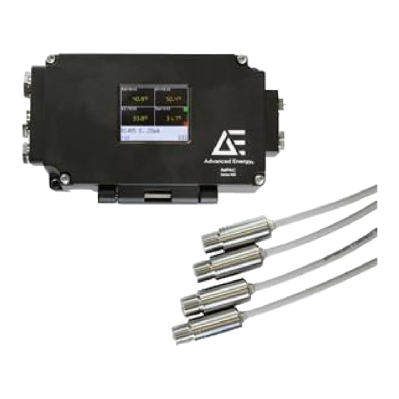
Advanced Energy Impac 600 Series User Manual (82 pages)
Pyrometer
Brand:
Advanced Energy
| Category:
Measuring Instruments
| Size: 1.02 MB
Table of Contents
Table of Contents
4
Chapter 1. Safety and Product Compliance Guidelines
9
Important Safety Information
9
Danger, Warning, and Caution Boxes
9
Safety Guidelines
9
Rules for Safe Installation and Operation
10
Interpreting Product Labels
10
Product Compliance
11
Product Certification
11
Safety and EMC Regulations, Directives, and Standards
11
Conditions of Use
11
Environmental Compliance
12
Chapter 2. Product Overview
13
General Description
13
Unit Components
13
Pyrometer
13
Sensor Heads
13
Sensor Cables
14
Converter Box
14
Analog Box
14
Multi-Sensor Box
14
Accessories
14
Unit Connectors
15
Sensor Head Connectors
15
Extension Cable Connectors
15
Table 2-1. Sensor Head Connector Pin Assignments (Male)
15
Figure 2-1. Standard Sensor Head Connector (Male)
15
Sensor Cable Connectors
16
Table 2-2. Sensor Cable Connector Pin Assignments (Female)
16
Figure 2-2. Extension Cable Connectors
16
Figure 2-3. Sensor Cable Connector (Female)
16
Converter Box Connectors
17
Analog Box Connectors
17
Figure 2-4. Converter Box Connectors
17
Multi-Sensor Box Connectors
18
Figure 2-5. Single-Analog Box Connectors
18
Figure 2-6. Multi-Analog Box Connectors
18
Software
19
Figure 2-7. Multi-Sensor Box Connectors
19
Chapter 3. Installation, Setup, and Operation
20
Preparing to Install the Unit
20
Unpacking the Unit
20
Measuring through External Windows
20
Verifying the Spot Size and Installation Location
20
Installation at any Measuring Distance
20
Installing the Unit
21
Mounting the Pyrometer
21
Figure 3-1. Spot Size from any Measuring Distance (Ratio)
21
Grounding the Pyrometer
22
Connecting the Sensor Cable
22
Figure 3-2. Ground Connection for the Converter Box
22
Figure 3-3. Connecting the Sensor Cable
22
Connecting the Sensor Head
23
Figure 3-4. Connected Sensor Cable
23
Connecting Input Power to the Unit
24
Connecting Serial Communications
25
Baud Rate
25
Cable Length
26
Connecting to an RS-232 Interface
26
Connecting to an RS-485 Interface
26
Connecting to PROFINET
27
Connecting to USB
28
Connecting Additional Devices
28
Connecting Multiple Analog Outputs
28
First Time Operation
29
Installing the Infra600 Software
29
Setting the Converter Box Address
30
Setting the Sensor Head Address
31
Normal Operation
32
Setting Pyrometer Parameters
32
Parameterizing with the Universal Pyrometer Protocols (UPP) Commands
32
Parameterizing Devices Using the Converter Box Display
34
Table 3-1. Soft Key Functions
34
Figure 3-5. Converter Box Display and Soft Keys
34
Parameterization Flowchart
35
Figure 3-6. Parameterization Process Flowchart
36
Exposure Time
37
Emissivity
37
Clear Time Interval for the Maximum Value Storage
38
Clear Time Interval
38
Wait Time
39
Temperature Display
39
Internal Pyrometer Temperature
39
Table 3-2. Clear Time Interval Settings
39
Limit Switch
40
Hysteresis
40
Maintenance
40
Replacing the Sensor Head
40
Periodic Calibration
41
Inspection and Cleaning
41
Refurbishment Schedule
41
Chapter 4. Troubleshooting and Technical Support Organization
42
Troubleshooting
42
Table 4-1. Troubleshooting Checklist
42
Technical Support Organization
44
Service, Repairs, and Upgrades
44
Appendix A. Unit Dimensional Drawings
47
Figure A-1. Sensor Head Dimensions with Sensor Cable
47
Figure A-2. High Temperature Sensor Head Dimensions with Sensor Cable
47
Figure A-3. Sensor Head Dimensions with Sensor Cable to USB
47
Figure A-4. Converter Box and Multi-Analog Box Dimensions
48
Figure A-5. Single-Analog Box Dimensions
49
Figure A-6. Multi-Sensor Box Dimensions
50
Appendix B. Unit Specifications
51
Physical Specifications
51
Table B-1. Physical Specifications
51
Temperature Measurement Specifications
52
Table B-2. Temperature Measurement Specifications
52
Electrical Specifications
54
Table B-3. Electrical Specifications
54
Cooling Specifications
55
Environmental Specifications
55
Table B-4. Air Cooling Specifications
55
Table B-5. Standard Environmental Specifications
55
Table B-6. Climatic Specifications
55
Appendix C. Spot Size Specifications
57
IN 600 and in 600/5 Pyrometer Spot Sizes
57
Table C-1. Optics 1N (2:1), −40°C to 700°C (−40°F to 1292°F
57
Table C-2. Optics 2N (10:1), −40°C to 700°C (−40°F to 1292°F
57
IS 600 Pyrometer Spot Sizes
58
IGA 600 and IGA 600/23 Pyrometer Spot Sizes
58
Table C-3. Optics 3N (20:1), −40°C to 700°C (−40°F to 1292°F
58
Table C-4. Optics (65:1
58
Table C-5. Optics (70:1
58
Appendix D. Factory Settings
59
Table D-1. Default Factory Settings
59
Appendix E. Pyrometer Parameters (Converter Box with Display)
60
Table E-1. Converter Box Parameters
60
Table E-2. Sensor Head Parameters
61
Appendix F. UPP Commands
62
Table F-1. Sensor Head UPP Commands
63
Table F-2. Converter Box and Analog Box UPP Commands
65
Table G-1. Emissivities for Spectral Range: 0.7 ΜM to 1.1 ΜM
72
Table G-2. Emissivities for Spectral Range: 1.45 ΜM to 1.8 ΜM
72
Table G-3. Emissivities for Spectral Range: 2 ΜM to 2.6 ΜM
73
Table G-4. Emissivities for Spectral Range: 8 ΜM to 14 ΜM
74
Appendix H. Wiring Diagrams for Multiple Analog Outputs
76
Possible Wiring for Differential Voltage Inputs
76
Possible Wiring for Simple, Non-Differential Voltage Inputs
77
Figure H-1. Wiring Example for Differential Voltage Inputs
77
Possible Wiring for Galvanically Separated Analog Inputs
78
Figure H-2. Wiring Example for Simple, Non-Differential Voltage Inputs
78
Figure H-3. Wiring Example for Galvanically Separated Input Modules
79
Advertisement
Advertisement
Related Products
Advanced Energy iLS600 Series
Advanced Energy iLS600-R Series
Advanced Energy iLS1500 Series
Advanced Energy 1314
Advanced Energy 1316
Advanced Energy 2818A
Advanced Energy LumaSense Technologies E2T QUASAR M8100FM-EXP
Advanced Energy LumaSense Technologies E2T QUASAR M8100PM-EXP
Advanced Energy LumaSense Technologies E2T QUASAR M8100SM-EXP
Advanced Energy LumaSense Technologies E2T QUASAR Series
Advanced Energy Categories
Measuring Instruments
Controller
Power Supply
Portable Generator
Inverter
More Advanced Energy Manuals
Login
Sign In
OR
Sign in with Facebook
Sign in with Google
Upload manual
Upload from disk
Upload from URL