Extron electronics TLP 1000MV User Manual
Touchlink touchpanel control systems
Hide thumbs
Also See for TLP 1000MV:
- User manual (60 pages) ,
- Setup manual (4 pages) ,
- User manual (54 pages)

Related Manuals for Extron electronics TLP 1000MV


Summary of Contents for Extron electronics TLP 1000MV
- Page 1 User Guide TouchLink™ TLP 1000MV and TLP 1000TV TouchLink Touchpanel Control Systems 68-1909-01 Rev. C 02 15...
- Page 2 Safety Instructions Safety Instructions • English Инструкция по технике безопасности • Русский WARNING: This symbol, , when used on the product, is intended ПРЕДУПРЕЖДЕНИЕ: Данный символ, , если указан to alert the user of the presence of uninsulated dangerous voltage на...
- Page 3 Extron Safety and Regulatory Compliance Guide on the Extron website. Copyright © 2015 Extron Electronics. All rights reserved. Trademarks All trademarks mentioned in this guide are the properties of their respective owners. The following registered trademarks( ®...
- Page 4 Conventions Used in this Guide Notifications In this user guide, the following are used: WARNING: Potential risk of severe injury or death. Risque potentiel de blessure grave ou de mort. AVERTISSEMENT : CAUTION: Risk of minor personal injury. Risque de blessure mineure. ATTENTION : ATTENTION: •...
-
Page 5: Table Of Contents
Rack Mounting ..........37 Software .............3 Rack Mounting the TLP 1000MV ......37 Hardware ............3 Wall Mounting the TLP 1000MV ......38 Wall Mounting the TLP 1000MV Directly i nto the Wall ............38 Panel Features ............4 Wall Mounting the TLP 1000MV TLP 1000MV Front Panel Features ......4 with a Wall Box ..........39... - Page 6 TLP 1000MV and TLP 1000TV • Contents...
-
Page 7: Introduction
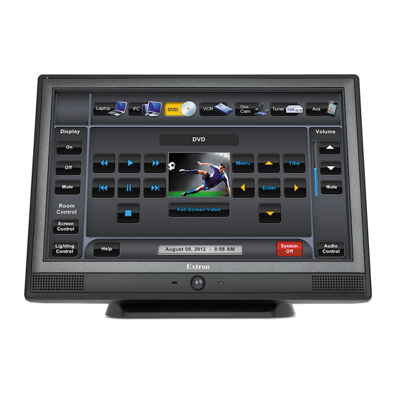
The TLP 1000MV is a wall- or rack-mounted TouchLink touchpanel. The TLP 1000TV comes with a stand that allows it to be placed on a desktop. If the stand is removed, the unit can be VESA mounted on a wall or furniture, using the optional Extron mounting kit. - Page 8 Automatic clock synchronization with the controller — provides accurate time and date display. Multiple mounting options The TLP 1000MV can be mounted in a rack (with optional kit), wall, lectern, or any flat • surface. The TLP 1000TV comes with a weighted base that allows up to 45° of tilt. It can stand on a •...
-
Page 9: Requirements
An Extron IP Link control interface must also be connected to the same network domain as the TouchLink panel. See www.extron.com for a list of suitable controllers. NOTE: These touchpanels and controllers are not compatible with the Extron Pro series of devices. TLP 1000MV and TLP 1000TV • Introduction... -
Page 10: Panel Features
These are configured for a range of user-defined functions, using the Extron Global Configurator software (see page 31). Speakers — (two) are located under the screen, on either side of the panel. They provide audible feedback for the user. TLP 1000MV and TLP 1000TV • Panel Features... -
Page 11: Reset Buttons And Led
There are two buttons and an LED recessed behind the faceplate. They can be accessed by removing the front bezel, using the Extron removal tool. Figure 4. TLP 1000MV Front Panel with the Bezel Removed Menu button — activates the on-screen menus for calibrating the unit (see page 16). -
Page 12: Tlp 1000Mv Rear Panel Features And Connections
MTP input — connect a twisted pair cable, terminated with an RJ-45 connector, to provide video and audio input from an Extron MTP transmitter. ATTENTION: The right RJ-45 connector on the back of the TLP 1000MV (with the yellow and • green LEDs) must be connected to a network. The left RJ-45 connector must be connected to an Extron MTP Transmitter. - Page 13 The TLP 1000MV can use a 12 VDC desktop power supply and is also Power over Ethernet (PoE 802.3af, class 3) compliant. Extron recommends using the XTP PI 100 power injector (part number 60-1233-01), which is shown in figure 6 below.
- Page 14 The power supply shall not be permanently fixed to building structure or similar • structure. La source d’alimentation ne devra pas être fixée de façon permanente à une structure • de bâtiment ou à une structure similaire. TLP 1000MV and TLP 1000TV • Panel Features...
- Page 15 These touchpanels ship with a power injector. If you wish to use a 12 VDC power • supply it must be purchased separately. If a 12 VDC and a PoE power supply are both connected to the touchpanel, the • power injector takes precedence. TLP 1000MV and TLP 1000TV • Panel Features...
- Page 16 • Ne pas étamer les conducteurs avant de les insérer dans le connecteur. Les câbles étamés ne sont pas aussi bien fixés dans le connecteur et pourraient être retirés. TLP 1000MV and TLP 1000TV • Panel Features...
-
Page 17: Tlp 1000Tv Front Panel Features And Operations
The sensor monitors the level of ambient light and adjusts the screen brightness and button backlighting. The sensor can only be viewed from above the panel. TLP 1000MV and TLP 1000TV • Panel Features... -
Page 18: Tlp 1000Tv Rear Panel Features And Connections
MTP signal adjustment controls — three MTP signal adjustments are available for S-video luminance gain (VID/Y), S-video chrominance gain (C), and sharpness (S). For composite video signals, the gain is controlled by the VID/Y adjustment. TLP 1000MV and TLP 1000TV • Panel Features... - Page 19 Connecting the Power over Ethernet Power Supply NOTE: The twisted pair cables providing the MTP and network connections should be secured together and to both the back panel and base using zip-ties (see figure on the next page). TLP 1000MV and TLP 1000TV • Panel Features...
- Page 20 Risk of Explosion if battery is replaced by an incorrect type. Dispose of used batteries according to the instructions. ATTENTION Risque d’explosion. Ne pas remplacer la pile par le mauvais type de pile. Débarrassez-vous des piles utilisées selon le mode d’emploi. TLP 1000MV and TLP 1000TV • Panel Features...
- Page 21 9) — allows the touchpanel to be locked to a table or other flat surface. The lock is not provided and must be purchased separately. Follow the installation instructions provided by the lock manufacturer. TLP 1000MV and TLP 1000TV • Panel Features...
-
Page 22: On-Screen Menus
(in 10-second increments). The time that is currently selected is shown above the buttons. When ambient lighting is high, the screen may need a high level of backlighting for readability. With low ambient lighting, the backlighting should be low. TLP 1000MV and TLP 1000TV • On-screen Menus... -
Page 23: Volume Screen
) sets the volume of audio from any audio file • playback. Line In (between ; default ) sets the volume of the audio signal received • through the line in from an Extron MTP transmitter. TLP 1000MV and TLP 1000TV • On-screen Menus... -
Page 24: Time Screen
, or digits between Clear , and “ ” (dot). NOTE: The factory default IP address for both the TLP 1000MV and TLP 1000TV is 192.168.254.254 . The default subnet mask is 255.255.0.0 . Consult with your IT department to ensure these addresses are correctly assigned. -
Page 25: Video Screen
Repeat until all four boxes have been pressed and calibrated. At that point the Main screen automatically returns to the screen (see page 16). Exit the on-screen menus, by pressing the Exit button in the bottom left corner of the menu screens. TLP 1000MV and TLP 1000TV • On-screen Menus... -
Page 26: Configuration Software
After assigning the control functions, the project is rebuilt and uploaded to the controller. These two programs provide versatility and adaptability for configuration and control of an AV system as it grows and evolves. TLP 1000MV and TLP 1000TV • Configuration Software... -
Page 27: Using The Touchlink Panel Web Pages
GUI Configurator and Global Configurator Installation NOTE: You must use Global Configurator 3.1 or a later version and GUI Configurator 1.2 or a later version to configure the TLP 1000MV or TLP 1000TV. Both programs can be downloaded from the Extron website (www.extron.com). Select the tab (see... - Page 28 Figure 21. Passwords Page To upgrade the firmware, select . More detailed instructions are found Firmware Upgrade in the Updating Firmware from a Web Browser section on page 25. TLP 1000MV and TLP 1000TV • Configuration Software...
-
Page 29: Updating The Firmware
Extron website (www.extron.com), select the Download tab and click the Software option in the sidebar at the left. Locate the Firmware Loader software and click Download Follow the on-screen instructions to complete installation. TLP 1000MV and TLP 1000TV • Configuration Software... -
Page 30: Updating Firmware Using Gui Configurator
Firmware Figure 23. Extron Web Page — Firmware Download Click the appropriate letter of the alphabet ( ) to navigate to the TLP 1000MV or TLP 1000TV firmware, click and follow the on-screen instructions. The firmware is Download downloaded to your computer. Note the folder in which the firmware file is saved. -
Page 31: Updating Firmware From A Web Browser
Open your browser and type the IP address of the TLP 1000 unit into the address box. The browser opens the TouchLink panel web pages (see page 21). Figure 25. Firmware Upgrade Web Page TLP 1000MV and TLP 1000TV • Configuration Software... -
Page 32: Using Gui Configurator
To use the GUI Configurator program, follow these instructions: Double-click the desktop icon. A splash screen appears momentarily and then the program opens at the main screen behind the dialog box. GUI Configurator Start Options Figure 26. Opening GUI Configurator TLP 1000MV and TLP 1000TV • Configuration Software... - Page 33 Touchlink panel. If you are creating a project from an existing template, you can use the factory created templates or you can select a template that you have previously created. TLP 1000MV and TLP 1000TV • Configuration Software...
- Page 34 Browse Check Open the project Close Download Manager Click . The project is downloaded to your computer and opens in GUI Configurator. TLP 1000MV and TLP 1000TV • Configuration Software...
- Page 35 If this is the first time saving the project file, the dialog appears. If the Save As Save As dialog appears: Browse to the location where the project file is to be saved. Enter a file name for the project. Click Save TLP 1000MV and TLP 1000TV • Configuration Software...
- Page 36 Automatic Settings Close this dialog when upload completes section so that the File Upload Manager screen closes automatically when the upload completes. This option can be set before or during the upload. TLP 1000MV and TLP 1000TV • Configuration Software...
-
Page 37: Using Global Configurator
Help File for exact information about the product you are using. Double-click the GC3 desktop icon. The Global Configurator 3 Start Options opens. Figure 34. Global Configurator 3 Start Options Select Create A New Project and click TLP 1000MV and TLP 1000TV • Configuration Software... - Page 38 If required, set the date and time ( Checking the box ( ) is optional. For more Set Device as GlobalViewer Host information about what a GlobalViewer host is, see the Global Configurator help file. Click TLP 1000MV and TLP 1000TV • Configuration Software...
- Page 39 If the controller is password protected, enter the password ( In the right panel ( ), set up a GlobalViewer tree, (see the Global Configurator Help File). Click ). The Add Device screen closes. TLP 1000MV and TLP 1000TV • Configuration Software...
- Page 40 ). The screen shows the available options for the TouchPanel Port 1 TouchLink panel. To add the GUI Configurator project that was uploaded to the TouchLink panel, click Click here to add one Figure 38. Adding a TouchLink Panel TLP 1000MV and TLP 1000TV • Configuration Software...
- Page 41 Configure the settings to add a touchpanel. Ensure the TouchLink panel model is selected from the menu ( Enter the IP address Set the ; default is Telnet port If necessary, enter the password Check Import/Apply Layout Click TLP 1000MV and TLP 1000TV • Configuration Software...
- Page 42 The window now shows the GUI from the TouchLink panel. Figure 40. Touchpanel GUI Loaded Onto Global Configurator 3 Use Global Configurator to associate functions with the screen elements designed in GUI Configurator (see the Global Configurator Help File). TLP 1000MV and TLP 1000TV • Configuration Software...
-
Page 43: Mounting
(such as the use of power strips). Rack Mounting the TLP 1000MV The TLP 1000MV can be mounted in any standard 19-inch equipment rack, using the optional Extron RM 1000M rack mounting kit. Follow the instructions provided with the kit. TLP 1000MV and TLP 1000TV • Mounting... -
Page 44: Wall Mounting The Tlp 1000Mv
Unpack the TLP 1000MV and remove the bezel, using the Extron removal tool. Ensure all the locking arms are flush with the unit and check that the TLP 1000MV can fit into the hole. If necessary, use a rasp or a coarse file to enlarge the hole. -
Page 45: Wall Mounting The Tlp 1000Mv With A Wall Box
Wall Mounting the TLP 1000MV with a Wall Box CAUTION: Fire Hazard — Do not install the TLP 1000MV in a fire resistant rated wall or partition assembly. ATTENTION : Risque d’incendie — Ne pas installer le TLP 1000MV dans un mur résistant au feu ou une cloison. -
Page 46: Furniture Mounting The Tlp 1000Mv
Unpack the TLP 1000MV and remove the bezel, using the Extron removal tool. Ensure all the locking arms are flush with the unit and check that the TLP 1000MV can fit into the hole. If necessary, use a rasp or a coarse file to enlarge the hole. -
Page 47: Desktop Mounting The Tlp 1000Tv
SMA-1. secure the touchpanel to the SMA-1 with the backing plate and locking nut. TLP 1000MV and TLP 1000TV • Mounting... -
Page 48: Removing The Tlp 1000Tv Base For Vesa Mounting
Remove the base cover by inserting the Extron removal tool into the notches on the base. VESA Mounting Holes (4) Spanner Drive Security Screws (2 for each Hinge) Hinges (2) Cable Runway Figure 46. TLP 1000TV with the Base and Back Covers Removed TLP 1000MV and TLP 1000TV • Mounting... -
Page 49: Vesa Mounting The Tlp 1000Tv
To VESA mount the TLP 1000TV with the LPVM-1, follow the instructions provided with the mounting kit. LPVM-1 Plate 2 Security Screws (4) Small Back Cover Hole for running cables Figure 47. VESA Mounting the TLP 1000TV with the LPVM-1 TLP 1000MV and TLP 1000TV • Mounting... -
Page 50: Reset Modes
Reset Modes The TLP 1000MV and TLP 1000TV have four reset modes that correspond to four of the five reset modes for the IP Link controllers. To maintain consistency with the controllers, the modes for touchpanels are numbered 1, 3, 4, and 5. -
Page 51: Mode 3 - Run Or Stop Events
• NOTE: Nothing happens if the momentary press does not occur within 1 second. Purpose and Notes This mode enables you to set IP address information, using ARP and the MAC address. TLP 1000MV and TLP 1000TV • Reset Modes... -
Page 52: Mode 5 - Reset To Factory Defaults
Nothing happens if the momentary press does not occur within 1 second. Purpose and Notes This mode is useful if you want to start over with configuration and uploading, and also to replace events. TLP 1000MV and TLP 1000TV • Reset Modes... - Page 53 Extron Electronics makes no further warranties either expressed or implied with respect to the product and its quality, performance, merchantability, or fitness for any particular use. In no event will Extron Electronics be liable for direct, indirect, or consequential damages resulting from any defect in this product even if Extron Electronics has been advised of such damage.
Need help?
Do you have a question about the TLP 1000MV and is the answer not in the manual?
Questions and answers