Extron electronics TouchLink TLP 1000MV User Manual
Control systems
Hide thumbs
Also See for TouchLink TLP 1000MV:
- User manual (54 pages) ,
- Setup manual (4 pages) ,
- Setup manual (4 pages)

Related Manuals for Extron electronics TouchLink TLP 1000MV


Summary of Contents for Extron electronics TouchLink TLP 1000MV
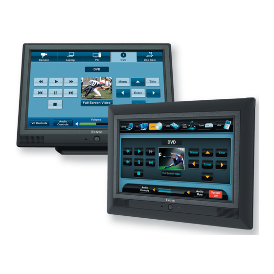
- Page 1 User Guide TouchLink™ TLP 1000MV and TLP 1000TV TouchLink Touchpanel Control Systems 68-1909-01 Rev. C 03 20...
- Page 2 Safety Instructions Safety Instructions • English Istruzioni di sicurezza • Italiano Il simbolo, , se usato sul prodotto, serve ad AVVERTENZA: WARNING This symbol, , when used on the product, is intended to avvertire l’utente della presenza di tensione non isolata pericolosa alert the user of the presence of uninsulated dangerous voltage within the all’interno del contenitore del prodotto che può...
- Page 3 より 『Extron Safety www.extron.com and Regulatory Compliance Guide』 (P/N 68-290-01) をご覧ください。 Copyright © 2015 - 2020 Extron Electronics. All rights reserved. Trademarks All trademarks mentioned in this guide are the properties of their respective owners. The following registered trademarks ( ®...
- Page 4 FCC Class A Notice This equipment has been tested and found to comply with the limits for a Class A digital device, pursuant to part 15 of the FCC rules. The Class A limits provide reasonable protection against harmful interference when the equipment is operated in a commercial environment. This equipment generates, uses, and can radiate radio frequency energy and, if not installed and used in accordance with the instruction manual, may cause harmful interference to radio communications.
- Page 5 Conventions Used in this Guide Notifications In this user guide, the following are used: WARNING: Potential risk of severe injury or death. AVERTISSEMENT : Risque potentiel de blessure grave ou de mort. CAUTION: Risk of minor personal injury. ATTENTION : Risque de blessure mineure.
-
Page 7: Table Of Contents
Contents Introduction ............1 Mounting ............... 37 TLP 1000MV and TLP 1000TV ........1 Rack Mounting the TLP 1000MV ......37 Features ..............1 Underwriters Laboratories Guidelines for Requirements ............3 Rack Mounting ..........37 Software .............3 Rack Mounting the TLP 1000MV ......37 Hardware ............3 Wall Mounting the TLP 1000MV ......38 Wall Mounting the TLP 1000MV Directly into the Wall .............38... - Page 8 TLP 1000MV and TLP 1000TV • Contents viii...
-
Page 9: Introduction
Introduction This guide describes the function, installation and operation of the TouchLink TLP 1000MV and TLP 1000TV panels. Unless otherwise stated, the terms “TLP 1000 Series,” “TLP 1000,” “touchpanel,” and “TouchLink touchpanel” refer to both models. The guide also provides information about optional accessories that are available from Extron for both touchpanels. This section provides information about: TLP 1000MV and TLP 1000TV •... - Page 10 Energy saving features — Adjustable sleep timer puts touchpanel into sleep mode. • Motion detector wakes the touchpanel. • Light sensor adjusts screen brightness as ambient room lighting changes. • Easy configuration and flexibility — using Extron software, on-screen graphics and text, as well as the functions associated with them, can be easily changed to adapt the control panel to the evolving needs of the system, avoiding the need for additional control modules.
-
Page 11: Requirements
Requirements Software For a complete list of the requirements for running Global Configurator 3 or GUI Configurator, see the Extron web page for that software. NOTE: These touchpanels and controllers are not compatible with GUI Designer or Global Configurator Plus and Global Configurator Professional. Hardware An Extron IP Link control interface must also be connected to the same network domain as the TouchLink panel. -
Page 12: Panel Features
Panel Features This section describes: TLP 1000MV Front Panel Features • TLP 1000MV Rear Panel Features and Connections • TLP 1000TV Front Panel Features and Operations • TLP 1000TV Rear Panel Features and Connections • TLP 1000MV Front Panel Features D D D D D D E E E... -
Page 13: Reset Buttons And Led
A A A Figure 3. TLP 1000MV Top View Light sensor — mounted on top of the display frame. The sensor monitors the level of ambient light and adjusts the screen brightness. The sensor can only be viewed from above the panel. -
Page 14: Tlp 1000Mv Rear Panel Features And Connections
TLP 1000MV Rear Panel Features and Connections A A A B B B C C C D D D Figure 5. TLP 1000MV Rear Panel Features MTP signal adjustment controls (see page 6) (see page 6) MTP input (see page 7) Network and Power over Ethernet connector Power connector (see page 9) - Page 15 Network and Power over Ethernet connector (see figure 5 on page 6) — the TLP 1000MV connects to a network using a twisted pair cable, terminated with an RJ-45 connector. LAN/PoE The network port has two LEDs. The green LED lights solid to indicate that the touchpanel is connected correctly to a network.
- Page 16 ATTENTION: The touchpanels are intended for connection to a Power over Ethernet circuit for intra- • building use only and are considered to be part of a Network Environment 0 per IEC TR62101. Les écrans tactiles sont conçu pour une connexion à un circuit PoE pour une utilisation •...
- Page 17 Power connector (see figure 5 on page 6) — connect the two pole, 3.5 mm captive screw connector from the 12 VDC, 1.0 A power supply (not provided) to the power supply socket on the rear panel. Ensure the connections have the correct polarity as shown below. Smooth Ridges Power Receptacle...
- Page 18 ATTENTION: • Always use a power supply provided by or specified by Extron. Use of an unauthorized power supply voids all regulatory compliance certification and may cause damage to the supply and the end product. • Utilisez toujours une source d’alimentation fournie ou recommandée par Extron. L’utilisation d’une source d’alimentation non autorisée annule toute conformité...
-
Page 19: Tlp 1000Tv Front Panel Features And Operations
TLP 1000TV Front Panel Features and Operations D D D D D D E E E A A A F F F B B B C C C Figure 8. TLP 1000TV Front Panel Features Motion sensor — is capped with a small Fresnel lens that focuses light onto the sensor. When no motion has been detected for a user-defined period of time, the unit enters sleep mode. -
Page 20: Tlp 1000Tv Rear Panel Features And Connections
TLP 1000TV Rear Panel Features and Connections The TLP 1000TV has a stand that allows it to be placed on a desktop. The stand can be removed to VESA mount the unit. Both the stand and the touchpanel have removable covers that conceal the rear panel features and protect cables that are attached to the TLP 1000TV. - Page 21 MTP input — a twisted pair cable, terminated with an RJ-45 connector, provides video and audio input from an Extron MTP transmitter. The MTP port is in the top surface of the figure 9 recessed area (see on page 12). ATTENTION: The left RJ-45 connector must be connected to an Extron MTP Transmitter.
- Page 22 LAN Connector MTP Connector Zip-tie Holder Cable Runway Zip-tie Holder Figure 11. Connecting and Securing Cables Power connector (see figure 9 on page 12) — connect the two pole, 3.5 mm captive screw connector from the 12 VDC, 1.0 A power supply (not provided) to the power supply socket on the rear panel.
- Page 23 ATTENTION: Do not power on the touchpanels or control processors until you have read the • Attention on page 10 (12 VDC power supply) or on page 8 (power injector). Ne branchez pas les écrans tactiles ou les contrôleurs avant d’avoir lu les mises •...
-
Page 24: On-Screen Menus
On-screen Menus This section describes: Accessing the On-screen Menus • Touch Calibration Screen • Accessing the On-screen Menus When the TouchLink panel first has power applied, the unit boots up and displays the opening screen. To access the on-screen menus, press the Menu button (see figure on page 5 for the TLP 1000MV or... - Page 25 With low ambient lighting, the backlighting should be low. Auto Backlight provides a suitable amount of backlighting that is automatically calculated from the amount of ambient light detected by the light detector. The Backlight control sets the backlighting manually from 0 to 100 percent, when Auto Backlight is set to Off.
- Page 26 Time Main Month: 07 Hours: 13 Volume Down Down Time Day: 06 Minutes: 32 Network Down Down Video Year: 2009 Down Exit Figure 15. Time Screen Use the Down or Up buttons to adjust the Month, Day, Year, Hours, and Minutes. NOTE: The Hours setting uses the 24-hour clock.
-
Page 27: Main Screen
Video Main Contrast: 064 Color: 064 Volume Down Down Time Brightness: 128 Tint: 128 Network Down Down Video Exit Figure 17. Video Screen When a video input is connected to the MTP input, the video can be previewed in the small gray rectangle on the screen. -
Page 28: Configuration Software
Configuration Software This section of the user guide provides information about: The Configuration Software • Installing the Software • Using the TouchLink Panel Web Pages • Updating the Firmware • Using GUI Configurator • Using Global Configurator • The Configuration Software Create a graphical user interface (GUI) for the TouchLink panel in two steps: Design the layout of the text and graphics using GUI Configurator. -
Page 29: Installing The Software
Installing the Software GUI Configurator and Global Configurator Installation Both programs can be downloaded from the Extron website (www.extron.com). Figure 19. Downloading Software Select the Download tab (figure 19, Click Software ( TLP 1000MV and TLP 1000TV • Configuration Software... - Page 30 The Software Download Center opens: Figure 20. Software Download Center Click on the GUI Configurator panel (1) or use the left (<) and right (>) arrows to find GUI Configurator. If the software is not in one of the panels at the top of the page, use the alphabet menu (3) to click on the first letter in the name of the software.
- Page 31 Downloading Software from the Product Page If you click on any of the panels at the top of the web page, you are taken to the product web page. Figure 21 shows the Global Configurator web page. Figure 21. Global Configurator Product Web Page To download and install the product, click Download ( ) and follow the onscreen instructions.
-
Page 32: Using The Touchlink Panel Web Pages
Using the TouchLink Panel Web Pages Both the TouchLink panels have default web pages that can be used to read and change the current settings of the panels. The web pages can be accessed as follows: Open your browser and type the IP address of the TLP 1000 unit into the address field. The browser opens the TouchLink panel Status page, which is read-only and provides basic information about the model, date and time, and IP settings. - Page 33 Figure 24. System Settings Page Selecting Passwords allows the user to set passwords for an administrator and a user. To set a password, follow the instructions at the top of the screen. Figure 25. Passwords Page NOTES: The factory configured passwords for all accounts on this device have been set to •...
- Page 34 Click the Touchpanel tab to open the Touchpanel Configuration page, which allows the user to alter the touchpanel and volume settings. These correspond to the Main (see page 16) and Volume (see page 17) screens in the on-screen menus. Figure 26. Touchpanel Configuration Page TLP 1000MV and TLP 1000TV •...
-
Page 35: Updating The Firmware
Updating the Firmware Firmware for both touchpanels can be upgraded using the Extron Firmware Loader, using the TLP 1000 default web page, or using GUI Configurator. Before starting, consult your IT team and ensure that the touchpanel has a unique IP address. If required, download and install the Extron Firmware Loader utility onto the computer. -
Page 36: Updating Firmware Using Extron Firmware Loader
Follow the on-screen instructions to download the program. An executable file is downloaded to the PC. Go to the Downloads folder and click on the file to install the firmware on the PC. By default, it is stored at C:\\Program Files (x86)\Extron\Firmware\<product name>\<firmware version>. -
Page 37: Updating Firmware Using Gui Configurator
Updating Firmware Using GUI Configurator Installing the If necessary, install the Extron Firmware Loader utility onto the computer (see Software on page 21). Find the firmware on the Extron website and download it to your computer, as described in steps 3 and 4 in the previous section. Open GUI Configurator. -
Page 38: Using Gui Configurator
Using GUI Configurator This section provides an overview of the GUI Configurator program. For complete information about the program, consult the GUI Configurator help file (select Contents in the Help menu or press the <F1> key while within the program). NOTES: To configure the touchpanel, use GUI Configurator version 1.2 or later. - Page 39 Select one of the following: Start a New Project (see page 31) • Open an Existing Project (see page 32) • Download an Existing Project from a Touchpanel (see page 33) • Start a New Project Click OK. A dialog opens offering a choice of project options. Figure 34.
- Page 40 Open an Existing Project Click OK. A dialog opens allowing you to navigate to an existing project for modification. Figure 35. GUI Configurator Dialog to Open an Existing Project Navigate to the existing file and select it. A preview with information about the file appears in the panel on the right.
- Page 41 Download an Existing Project from a Touchpanel Click OK. A dialog box opens that allows you to download a file that has been uploaded to a panel. Figure 36. GUI Configurator Download Project Dialog In the dialog that opens, enter the IP address of the panel. If necessary, enter a password.
- Page 42 Depending on which option was selected in step 2, GUI Configurator opens to a new or existing project. The initial screen is divided into a series of panels offering a range of tools that can be used to design or modify the project. For full details on how to use these tools, consult the help file (in the Help menu click Contents, or press the <F1>...
- Page 43 The project can be uploaded to one or more TouchLink panels. To add a panel: From the Project menu, select Add > Panel (figure 32, 1 1 1 2 2 2 Figure 38. Add a TouchLink Panel The Panel Manager dialog box opens: 1 1 1 2 2 2 3 3 3...
-
Page 44: Using Global Configurator
If this project has been uploaded to the TouchLink panel before, you can choose to upload only the changes that have been made since the previous upload. You can also choose to upload the new version to some, specified touchpanels or all the TouchLink panels on the list found within the Devices section of the File Upload Manager screen during the upload process. - Page 45 The dialog closes, leaving the Project Settings screen. 1 1 1 2 2 2 3 3 3 4 4 4 5 5 5 6 6 6 Figure 41. Global Configurator Project Settings Configure the device settings: Enter the IP address for the IP Link control processor ( The default Telnet Port is 23 and HTTP (Web) Port is 80 ( ).
- Page 46 The Project Settings screen closes and is replaced by the Add Device dialog: 2 2 2 8 8 8 1 1 1 3 3 3 4 4 4 5 5 5 6 6 6 7 7 7 9 9 9 Figure 42.
- Page 47 The start-up screen, which was behind the Add Device screen, is now visible, showing the IP Link control processor and the available ports: Figure 43. Configuring an IP Link Device Select TouchPanel Port 1 ( ). The screen shows the available options for the TouchLink panel.
- Page 48 The Add TouchPanel dialog box opens. 1 1 1 2 2 2 3 3 3 4 4 4 5 5 5 6 6 6 Figure 45. Add TouchPanel Dialog Box Configure the settings to add a touchpanel. Ensure the TouchLink panel model is selected from the menu ( Enter the IP address ( ;...
- Page 49 The window now shows the GUI from the TouchLink panel. Figure 46. Touchpanel GUI Loaded Onto Global Configurator 3 Use Global Configurator to associate functions with the screen elements designed in GUI Configurator (see the Global Configurator Help File). TLP 1000MV and TLP 1000TV • Configuration Software...
-
Page 50: Mounting
Mounting This section outlines the various options for: Rack Mounting the TLP 1000MV • Wall Mounting the TLP 1000MV • Furniture Mounting the TLP 1000MV • Desktop Mounting the TLP 1000TV • Removing the TLP 1000TV Base for VESA Mounting • Rack Mounting the TLP 1000MV Underwriters Laboratories Guidelines for Rack Mounting The following Underwriters Laboratories (UL) guidelines are relevant to the safe installation of... -
Page 51: Wall Mounting The Tlp 1000Mv
Wall Mounting the TLP 1000MV The TLP 1000MV can be mounted in the wall or through furniture. Wall Mounting the TLP 1000MV Directly into the Wall CAUTION: Fire Hazard — Do not install the TLP 1000MV in a fire resistant rated wall or partition assembly. -
Page 52: Wall Mounting The Tlp 1000Mv With A Wall Box
Using a Phillips head screwdriver, tighten the screws for the locking arms. As the screws tighten, the locking arms rotate behind the wall and hold the unit in place. Do not overtighten the screws as this can damage the locking arms or the wall. Locking Arms Faceplate snaps to unit (3 on top edge,... -
Page 53: Furniture Mounting The Tlp 1000Mv
Furniture Mounting the TLP 1000MV The TLP 1000MV can be mounted into the surface of a lectern as follows. Determine the best location for the TLP 1000MV. Use the template provided to mark the lectern and then cut a hole 10.22 inches (25.96 cm) wide x 7.16 inches (18.2 cm) high (figure 42, Unpack the TLP 1000MV and remove the bezel, using the Extron removal tool. -
Page 54: Desktop Mounting The Tlp 1000Tv
Desktop Mounting the TLP 1000TV Freestanding The TLP 1000TV is shipped with an attached stand that allows it to be placed on a desktop. There are two mounting holes in the bottom surface of the stand. If required, these can be used to secure the unit to the desktop. -
Page 55: Removing The Tlp 1000Tv Base For Vesa Mounting
Removing the TLP 1000TV Base for VESA Mounting The TLP 1000TV can be VESA mounted, using the Extron LPVM-1 kit. To use this kit, it is necessary to remove the back cover and the base. Notch to Remove Back Cover Notch to Remove Base Cover Figure 51. -
Page 56: Vesa Mounting The Tlp 1000Tv
If necessary, cut the zip tie holding the twisted pair cables to the TLP 1000TV base. If necessary, remove the cables from the cable runway in the base. Remove the four screws holding the hinges to the touchpanel. NOTE: The spanner drive screws holding the hinges require a #6 spanner bit or #6 spanner head screwdriver, which are not provided. -
Page 57: Reset Modes
Reset Modes The TLP 1000MV and TLP 1000TV have four reset modes that correspond to four of the five reset modes for the IP Link controllers. To maintain consistency with the controllers, the modes for touchpanels are numbered 1, 3, 4, and 5. Mode 1 —... -
Page 58: Mode 3 - Run Or Stop Events
Mode 3 — Run or Stop Events Activation Hold down the Reset button for approximately 3 seconds until the Reset LED blinks once. Then release and press the Reset button momentarily (less than 1 second) within 1 second. NOTE: Nothing happens if the momentary press does not occur within 1 second. Result This mode turns events on or off. -
Page 59: Mode 5 - Reset To Factory Defaults
Mode 5 — Reset to Factory Defaults Activation Hold down the Reset button for approximately 9 seconds until the Reset LED blinks three times (at 3, 6, and 9 seconds). Then release and press the Reset button momentarily (less than 1 second) within 1 second. NOTE: Nothing happens if the momentary press does not occur within 1 second. - Page 60 In the event of malfunction during the warranty period attributable directly to faulty workmanship and/or materials, Extron Electronics will, at its option, repair or replace said products or components, to whatever extent it shall deem necessary to restore said product to proper operating condition, provided that it is returned within the warranty period, with...
Need help?
Do you have a question about the TouchLink TLP 1000MV and is the answer not in the manual?
Questions and answers