Extron electronics TLP 1000MV User Manual
Extron electonics touchlink touchpanels user guide
Hide thumbs
Also See for TLP 1000MV:
- User manual (60 pages) ,
- Setup manual (4 pages) ,
- User manual (53 pages)
Table of Contents
Advertisement
Quick Links
Download this manual
See also:
Setup Manual
Advertisement
Table of Contents

Related Manuals for Extron electronics TLP 1000MV


Summary of Contents for Extron electronics TLP 1000MV
- Page 1 User Guide TouchLink ™ TLP 1000MV and TLP 1000TV TouchLink Touchpanels 68-1909-01 Rev. B 01 12...
- Page 2 Safety Instructions • English Warning Power sources • This equipment should be operated only from the power source indicated on the product. This This symbol is intended to alert the user of important operating and equipment is intended to be used with a main power system with a grounded (neutral) conductor. The third maintenance (servicing) instructions in the literature provided with the (grounding) pin is a safety feature, do not attempt to bypass or disable it.
- Page 3 FCC Class A Notice This equipment has been tested and found to comply with the limits for a Class A digital device, pursuant to part 15 of the FCC Rules. Operation is subject to the following two conditions: This device may not cause harmful interference. This device must accept any interference received, including interference that may cause undesired operation.
- Page 4 Selectable items, such as menu names, menu options, buttons, tabs, and field names are written in the font shown here: From the menu, select File Click the button. Copyright © 2012 Extron Electronics. All rights reserved. Trademarks All trademarks mentioned in this guide are the properties of their respective owners...
-
Page 5: Table Of Contents
Contents Specifications Introduction ............34 ............1 About the TLP 1000MV and TLP 1000TV .... 1 Features .............. 1 Accessories and Part Numbers ......40 Requirements ............3 Included Parts ..........40 Computer Software and Hardware ....3 Optional Parts ..........40 Other Hardware .......... - Page 6 TLP 1000MV and TLP 1000TV • Contents...
-
Page 7: Introduction
This guide describes the function, installation and operation of the TouchLink ™ TLP 1000MV and TLP 1000TV panels. Unless otherwise stated, the terms “TLP 1000 Series,” “TLP 1000,” “touchpanel,” and “TouchLink panel” refer to both models. The guide also provides information about optional accessories that are available from Extron for both panels. - Page 8 VESA-mounted on a wall or furniture using the Extron LPVM-1. See the list of optional parts on page 40 for the part numbers. Choice of colors for TLP 1000MV — The TLP 1000MV is available in • black (part number 60-1105-02) •...
-
Page 9: Requirements
IPL T S series (for example IPL T S4) • IPL 250 • IPL T CR48 • IPL T SFI244 • IPCP 305 • IPCP 505 See the Extron Website (www.extron.com) for further information about these products. TLP 1000MV and TLP 1000TV • Introduction... -
Page 10: Panel Features
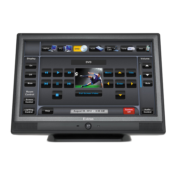
TLP 1000MV Rear Panel Features and Connections TLP 1000TV Front Panel Features and Operations TLP 1000TV Rear Panel Features and Connections TLP 1000MV Front and Top Panel Features and Operations Figure 2. TLP 1000MV Front Panel Motion sensor — is capped with a small Fresnel lens that focuses light onto the sensor. -
Page 11: Reset Buttons And Led
Reset Buttons and LED There are two buttons and an LED recessed behind the faceplate. Figure 4. TLP 1000MV Front Panel with the Bezel Removed Menu button — activates the on-screen menus for calibrating the unit (see page 14). -
Page 12: Tlp 1000Mv Rear Panel Features And Connections
MTP transmitter and the network socket (on the right) must be connected to a LAN. The wires on each connector use different voltages and inputting the wrong voltages into a socket will damage the TLP 1000MV. TLP 1000MV and TLP 1000TV • Panel Features... - Page 13 Connect a second straight-through cable to carry the network information and 48 VDC from the power supply to the TLP 1000MV. Connect the IEC power cord from the PoE power supply to a convenient 100 VAC to 240 VAC, 50-60 Hz power source.
- Page 14 NOTES: • Extron recommends using the Power over Ethernet power supply. This 12 VDC, 1.0 A power supply should be used only for setup or troubleshooting. • If both power supplies are connected to the TLP 1000MV, the PoE power supply takes precedence. Smooth...
-
Page 15: Tlp 1000Tv Front Panel Features And Operations
The sensor monitors the level of ambient light and adjusts the screen brightness and button backlighting. The sensor can only be viewed from above the panel. TLP 1000MV and TLP 1000TV • Panel Features... -
Page 16: Tlp 1000Tv Rear Panel Features And Connections
MTP signal adjustment controls — three MTP signal adjustments are available for S-video luminance gain (VID/Y), S-video chrominance gain (C), and sharpness (S). For composite video signals, the gain is controlled by the VID/Y adjustment. TLP 1000MV and TLP 1000TV • Panel Features... - Page 17 NOTE: The twisted pair cable providing the MTP and network connections should be secured together and to both the back panel and base using zip-ties figure 11, on the next page). (see TLP 1000MV and TLP 1000TV • Panel Features...
- Page 18 Figure 12. Power Supply Connection CAUTION: See the cautions on page 8 for important information about power supplies. NOTE: notes See the on page 8 for important information about wiring captive screw connectors. TLP 1000MV and TLP 1000TV • Panel Features...
- Page 19 “VESA mounting the TLP 1000TV” on page 46). Kensington Security Slot — allows the touchpanel to be locked to a table or other flat surface. The lock is not provided and must be purchased separately. TLP 1000MV and TLP 1000TV • Panel Features...
-
Page 20: Initial Calibration
Values can be changed by pressing the buttons to highlight them. Press the Down buttons to adjust the values or press the Auto Backlight or Wake on Motion buttons to toggle between . The current setting is shown above the buttons. TLP 1000MV and TLP 1000TV • Initial Configuration and Calibration... -
Page 21: Volume Screen
) sets the volume of audio from any audio file playback. • Line In (between ; default ) sets the volume of the audio signal received through the line in from an Extron MTP transmitter. TLP 1000MV and TLP 1000TV • Initial Configuration and Calibration... -
Page 22: Time Screen
,” or digits between , and “ ” (dot). NOTE: The factory default IP address for both the TLP 1000MV and TLP 1000TV is . The default subnet mask is . Consult with 192.168.254.254 255.255.0.0 your IT department to ensure these addresses are correctly assigned. -
Page 23: Video Screen
Main screen (see page 14). Exit the on-screen menus, by pressing the button in the bottom left corner of the Exit menu screens. TLP 1000MV and TLP 1000TV • Initial Configuration and Calibration... -
Page 24: Configuration Software
NOTE: You must use Global Configurator 3.1 or a later version and GUI Configurator 1.2 or a later version to configure the TLP 1000MV or TLP 1000TV. Insert the disc provided into the DVD-ROM drive of the computer. If the setup program does not start automatically, run Launch.exe... -
Page 25: Using The Touchlink Panel Web Pages
Open your browser and type the IP address of the TLP 1000 unit into the address field. The browser opens the TouchLink panel Status page, which is read-only and provides basic information about the model, date and time, and IP settings. Figure 19. System Status Page TLP 1000MV and TLP 1000TV • Configuration Software... - Page 26 To set a password, follow the instructions at the top of the page. Figure 21. Passwords Page To upgrade the firmware, select . More detailed instructions are Firmware Upgrade “Updating Firmware from a Web Browser” section on page 23. found in the TLP 1000MV and TLP 1000TV • Configuration Software...
-
Page 27: Updating The Firmware
(see page 18). To install from the Extron website (www.extron.com), select the tab and Download click the Software tab. Locate the Firmware Loader and click Download . Follow the on-screen instructions to complete installation. TLP 1000MV and TLP 1000TV • Configuration Software... -
Page 28: Updating Firmware Using Gui Configurator
Download Firmware Figure 23. Extron Web Page — Download Center Navigate to the TLP 1000MV or TLP 1000TV firmware and click Download This downloads the firmware to your computer. Note the folder in which the firmware file is saved. Open the Extron Firmware Loader by clicking on the desktop icon. -
Page 29: Updating Firmware From A Web Browser
Please Wait...”. When the firmware is uploaded, the screen shows the message “Restarting...”. Once the firmware is installed, the panel can be calibrated using the on-screen menus (see page 14) or the TouchLink panel web pages (see page 19). TLP 1000MV and TLP 1000TV • Configuration Software... -
Page 30: Using Gui Configurator
Double-click the desktop icon. A splash screen appears momentarily and then the program opens at the main screen behind the GUI Configurator Start Options dialog box. Figure 26. Opening GUI Configurator Figure 27. GUI Configurator Start Options Dialog Box TLP 1000MV and TLP 1000TV • Configuration Software... - Page 31 — Clicking opens a dialog box that allows you Open an Existing Project • to navigate to an existing project for modification. Figure 29. GUI Configurator Dialog Box to Open an Existing Project TLP 1000MV and TLP 1000TV • Configuration Software...
- Page 32 Browse Check Open the project Close Download Manager Click . The project is downloaded to your computer and opens in GUI Configurator. TLP 1000MV and TLP 1000TV • Configuration Software...
- Page 33 If this is the first time saving the project file, the Save As dialog box appears. If the Save As dialog box appears: Browse for the location where the project file is to be saved. Enter a file name for the project. Click Save TLP 1000MV and TLP 1000TV • Configuration Software...
- Page 34 Close this dialog when upload completes check box in the Automatic Settings section so that the File Upload Manager screen closes automatically when the upload completes. This option can be set before or during the upload. TLP 1000MV and TLP 1000TV • Configuration Software...
-
Page 35: Using Global Configurator
Configurator help file for exact information about the product you are using. Double-click the GC3 desktop icon. The Global Configurator 3 Start Options box opens. Figure 34. Global Configurator 3 Start Options TLP 1000MV and TLP 1000TV • Configuration Software... - Page 36 If required, set the date and time. Checking the box is optional. For more Set Device as GlobalViewer Host information about what a GlobalViewer host is, see the Global Configurator help file. TLP 1000MV and TLP 1000TV • Configuration Software...
- Page 37 Set the Telnet port (usually 23) and the web port (usually 80). If the controller is password protected, enter the password now. In the right pane, set up a GlobalViewer tree, (see the Global Configurator help file). TLP 1000MV and TLP 1000TV • Configuration Software...
- Page 38 . The screen shows the available options for the TouchLink TouchPanel Port 1 panel. To add the GUI Configurator project that was uploaded to the TouchLink panel, click Click here to add one Figure 38. Adding a TouchLink Panel TLP 1000MV and TLP 1000TV • Configuration Software...
- Page 39 The window now shows the GUI from the TouchLink panel. Figure 40. Touchpanel GUI Loaded Onto Global Configurator 3 Use Global Configurator to associate functions with the screen elements designed in GUI Configurator (see the Global Configurator help file). TLP 1000MV and TLP 1000TV • Configuration Software...
-
Page 40: Specifications
GUI Configurator v1.2 or higher for Windows ® Extron Simple Instruction Set (SIS ™ Microsoft Internet Explorer ver. 6 or higher, Telnet ® ® Control — touchpanel Motion sensor ........ On/off Light sensor ........On/off TLP 1000MV and TLP 1000TV • Specifications... - Page 41 Device ........43.5 BTU/hr Device and power supply ..52.3 BTU/hr Mounting Rack mount ......With optional kit Furniture or wall mount ... With included hardware or optional accessores Enclosure type ........ Plastic TLP 1000MV and TLP 1000TV • Specifications...
- Page 42 MTBF ..........30,000 hours Warranty ........3 years parts and labor; touchscreen display and overlay components are covered for 1 year NOTE: All nominal levels are at ±10%. NOTE: Specifications are subject to change without notice. TLP 1000MV and TLP 1000TV • Specifications...
- Page 43 Audio input — see S-video or composite video MTP transmitters' specifications Number/signal type ......1 stereo, balanced/unbalanced, line level, as part of a set of proprietary signals from an Extron MTP Connector ........1 female RJ-45 (shared with video input) TLP 1000MV and TLP 1000TV • Specifications...
- Page 44 Device and power supply ..52.3 BTU/hr Mounting Furniture or wall mount ... Set on tabletop or mount to optional VESA D 75 mm panel mount kit Adjustment ranges ......Tilts through a 45° range Enclosure type ........ Plastic TLP 1000MV and TLP 1000TV • Specifications...
- Page 45 MTBF ..........30,000 hours Warranty ........3 years parts and labor; touchscreen display and overlay components are covered for 1 year NOTE: All nominal levels are at ±10%. NOTE: Specifications are subject to change without notice. TLP 1000MV and TLP 1000TV • Specifications...
-
Page 46: Accessories And Part Numbers
Power over Ethernet power supply 70-828-01 Extron removal tool Extron Software Products DVD Cut-out Template (TLP 1000MV only) TLP 1000MV Setup Guide or TLP 1000TV Setup Guide Optional Parts Description Part Number RM 1000M rack mounting kit for TLP 1000MV... -
Page 47: Mounting
(such as the use of power strips). Rack Mounting the TLP 1000MV The TLP 1000MV can be mounted in any standard 19-inch equipment rack, using the optional Extron RM 1000M rack mounting kit (part number 70-886-01). Follow the instructions provided with the kit. -
Page 48: Wall Mounting The Tlp 1000Mv
Unpack the TLP 1000MV and remove the faceplate. Ensure all the locking arms are flush with the unit and check that the TLP 1000MV can fit into the hole. If necessary, use a rasp or a coarse file to enlarge the hole. -
Page 49: Furniture Mounting The Tlp 1000Mv
Unpack the TLP 1000MV and remove the faceplate. Ensure all the locking arms are flush with the unit and check that the TLP 1000MV can fit into the hole. If necessary, use a rasp or a coarse file to enlarge the hole. -
Page 50: Wall Mounting The Tlp 1000Mv With A Wall Box
Wall Mounting the TLP 1000MV with a Wall Box The TLP 1000MV can be wall mounted using the Extron BB 1000M back box (part number 70-887-01) or the Extron EWB 1000M external wall box (part number 70-950-0x). Follow the instructions provided with the appropriate wall box. -
Page 51: Removing The Tlp 1000Tv Base For Vesa Mounting
Remove the base cover by inserting the Extron removal tool into the notches on the base. VESA Mounting Holes (4) Spanner Drive Security Screws (2 for each Hinge) Hinges (2) Cable Runway Figure 46. TLP 1000TV with the Base and Back Covers Removed TLP 1000MV and TLP 1000TV • Mounting... -
Page 52: Vesa Mounting The Tlp 1000Tv
2 of the Extron LPVM-1 (part number 60-1099-02) to the four VESA mounting holes (see the figure below). Follow the instructions provided with the mounting kit. LPVM-1 Plate 2 Security Screws (4) Small Back Cover Figure 47. VESA Mounting the TLP 1000TV with the LPVM-1 TLP 1000MV and TLP 1000TV • Mounting... -
Page 53: Reset Modes
Reset Modes The TLP 1000MV and TLP 1000TV have four reset modes that correspond to four of the five reset modes for the IP Link controllers. The modes are initiated by pressing the Reset button. To access the Reset button on the TLP 1000MV, remove the faceplate. See page 5 to... - Page 54 Extron Warranty Extron Electronics warrants this product against defects in materials and workmanship for a period of three years from the date of purchase; touchscreen display and overlay components are covered for 1 year. In the event of malfunction during the warranty period attributable directly to faulty workmanship and/or materials, Extron Electronics will, at...
Need help?
Do you have a question about the TLP 1000MV and is the answer not in the manual?
Questions and answers