
Related Manuals for Extron electronics TouchLink TLP Pro 525C Series


Summary of Contents for Extron electronics TouchLink TLP Pro 525C Series
- Page 1 User Guide TouchLink ® TLP Pro 525C and 725C Series TouchLink Pro Touchpanel Control Systems 68-3319-01 Rev. D 01 20...
- Page 2 Safety Instructions Safety Instructions • English Istruzioni di sicurezza • Italiano AVVERTENZA: Il simbolo, , se usato sul prodotto, serve ad This symbol, , when used on the product, is intended to WARNING avvertire l’utente della presenza di tensione non isolata pericolosa alert the user of the presence of uninsulated dangerous voltage within the all’interno del contenitore del prodotto che può...
- Page 3 より 『Extron Safety www.extron.com and Regulatory Compliance Guide』 (P/N 68-290-01) をご覧ください。 Copyright © 2018 - 2020 Extron Electronics. All rights reserved. www.extron.com Trademarks All trademarks mentioned in this guide are the properties of their respective owners. The following registered trademarks ( ®...
- Page 4 FCC Class B Notice NOTE: This device complies with part 15 of the FCC rules. Operation is subject to the following two conditions: (1) This device may not cause harmful interference, and (2) This device must accept any interference received, including interference that may cause undesired operation.
- Page 5 Class 1 Laser Product Any service to this product must be carried out by Extron Electronics and its qualified service personnel. CAUTION: Using controls, making adjustments, or performing procedures in a manner other than what is specified herein may result in hazardous radiation exposure.
- Page 6 Compliance IC Canada, Industry Canada (IC) Notices CAN ICES-3 (B)/NMB-3(B) This device complies with Industry Canada licence-exempt RSS standard(s). Operation is subject to the following two conditions: (1) this device may not cause interference, and (2) this device must accept any interference, including interference that may cause undesired operation of the device.
- Page 7 IC conformité Canada, avis d’Industry Canada (IC) CAN ICES-3 (B)/NMB-3(B) Cet appareil est conforme aux normes des cahiers des charges sur les normes radioélectriques (CNR) de l’ISDE applicables aux appareils exempts de licence. Son utilisation est subordonnée aux deux conditions suivantes : (1) Cet appareil ne doit provoquer aucune interférence, et (2) cet appareil doit accepter toute interférence, y compris l’interférence susceptible de compromettre son fonctionnement.
- Page 8 Conventions Used in this Guide Notifications In this user guide, the following are used: WARNING: Potential risk of severe injury or death. AVERTISSEMENT : Risque potentiel de blessure grave ou de mort. CAUTION: Risk of minor personal injury. ATTENTION : Risque de blessure mineure.
-
Page 9: Table Of Contents
Contents Introduction On-screen Menus ............1 ..........26 About the TLP Pro 525C and 725C Series ....1 Setup Menu ............26 Features ..............2 Status ...............26 Application Diagram ..........3 Network ............27 Requirements ............4 Display ..............29 Software .............4 Audio ..............30 Hardware ............4 Advanced ............31 Panel Features Configuration Software ............ - Page 10 TLP Pro 525C and 725C Series Touchpanels • Contents...
-
Page 11: Introduction
Introduction This guide describes the function, installation, and operation of the Extron Touchlink Pro Touchpanels: TLP Pro 525C • TLP Pro 525C NC • TLP Pro 725C • TLP Pro 725C NC • Unless otherwise stated: The terms “TLP Pro 525C” or “TLP Pro 525C Series” refer to both the 525C and 525C NC •... -
Page 12: Features
Features LCD touchscreen • TLP Pro 525C — 5" capacitive flip-up touchscreen with 800x480 (WVGA) resolution • TLP Pro 725C — 7" capacitive flip-up touchscreen with 1024x600 (WSVGA) resolution • 24-bit color depth. Vibrant edge-to-edge glass display with a more responsive control •... -
Page 13: Application Diagram
Motion detector wakes the touchpanel. • Integrated lid switch automatically wakes the touchpanel when opened and can trigger • any other system function. Manage, monitor, and control this device remotely — using GlobalViewer Enterprise • (GVE) Resource Management software. Fully customizable using Extron control system software — GUI Designer combined •... -
Page 14: Requirements
Requirements Software For a complete list of the requirements for running GUI Designer, Global Configurator Plus and Professional, Global Scripter, and Toolbelt see the Extron web page (www.extron.com) for that software. NOTE: These touchpanels are not compatible with Global Configurator 3 or GUI Configurator. -
Page 15: Panel Features
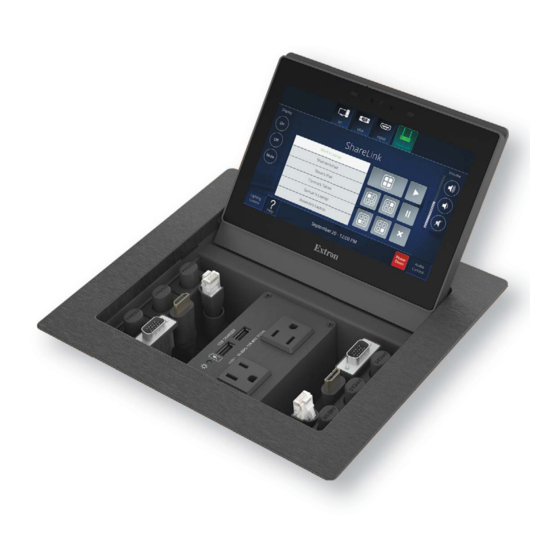
Panel Features This section describes the TLP Pro touchpanels: Front Panel and Enclosure Features • Base Features • Front Panel and Enclosure Features Figure 2 shows the TLP Pro 725C front panel and the Cable Cubby enclosure. The TLP Pro 525C is very similar. B B B C C C D D D... -
Page 16: Base Features
Communication LED (see figure 2 on the previous page) — Shows the configuration and connection status of the touchpanel: Unlit during normal operation (the touchpanel is configured and connected to an IP Link • Pro control processor). Blinks red if the touchpanel has been configured but is not connected to an IP Link Pro •... - Page 17 ATTENTION: The installation must always be in accordance with the applicable provisions of National • Electrical Code ANSI/NFPA 70, article 725 and the Canadian Electrical Code part 1, section 16. Cette installation doit toujours être conforme aux dispositions applicables du Code •...
- Page 18 Connect a straight-through Ethernet cable from the power injector to a switch or router (figure 14, ). This cable carries network information from the switch or router to the power supply input. Connect a second straight-through cable ( ) from the power injector to the touchpanel. This cable carries the network information and 48 VDC from the power injector to the touchpanel.
-
Page 19: Installation Overview
Installation Overview This section provides an overview of the installation process. Follow the links for a more detailed explanation of each step. Before starting to install the touchpanel, download and install the latest versions of the following software: … GUI Designer — For designing layouts for Extron TouchLink Pro touchpanels and third party touch interfaces. - Page 20 Run all cables to the touchpanel. These include Ethernet cable and cables for Retractors, power modules, AAPs, and MAAPs (see Running Cables on page 16). Leave enough slack to connect the cables before the enclosure is installed in the table. Set up the touchpanels for network communication: NOTE: If you use the setup menu to configure the touchpanel, configure the touchpanel before mounting (see step 8, below) as you will need access to the...
-
Page 21: Mounting
Mounting This section outlines the various options for: Planning • Tools Required for Installation • Included Parts • Ensuring Adequate Under-table Clearance for Retractors • Cutting the Table • Running Cables • Preparing MAAP or AAP Modules • Preparing Cable Pass-through Modules •... -
Page 22: Tools Required For Installation
Tools Required for Installation The following tools are required for installation and must be provided by the installer: Phillips Screw Driver Tape Measure Safety Glasses 1/4" Hex Nut Driver Marking Pen Vacuum Cleaner Figure 5. Tools Required to Install the TLP Pro 525C or 725C Series Touchpanels Included Parts Open the shipping container and verify that the following parts are present. -
Page 23: Ensuring Adequate Under-Table Clearance For Retractors
Ensuring Adequate Under-table Clearance for Retractors Retractors are optional accessories for managing cables with these touchpanels. If you are using retractors, ensure that there is sufficient room beneath the table to accommodate them. Horizontal mounting provides maximum legroom and protects the retractors from accidental •... -
Page 24: Retractor Clearance For The Tlp Pro 725C Series
Retractor Clearance for the TLP Pro 725C Series Retractor Mounting Clearance 1.60" 15.00" 41 mm 381 mm 17.00" 23.6" 432 mm 599 mm Standard Models 1.60" 21.00" 41 mm 533 mm 23.00" 584 mm 29.6" 752 mm XL Models Figure 9. Under-table Retractor Clearance Requirements for the TLP Pro 725C Series TLP Pro 525C and 725C Series Touchpanels •... -
Page 25: Cutting The Table
Cutting the Table Cut-out Dimensions There are three methods of making the hole for the touchpanel (see “Cutting the Surface” below): If using a Hand router and guide (see the next page) you must purchase the correct metal • router guide (see www.extron.com). TLP Pro 525C —... -
Page 26: Running Cables
Hand router and guide Recommended method — use the correct metal router guide for your touchpanel. It is reusable and should not be discarded when the installation is complete. TLP Pro 525C: part number 70-694-01 (see www.extron.com). TLP Pro 725C: part number 70-980-01 (see www.extron.com). Follow the instructions provided in the Routing Template User Guide (see www.extron.com). -
Page 27: Preparing Maap Or Aap Modules
Preparing MAAP or AAP Modules If required, MAAPs or AAPs must be purchased separately. Go to www.extron.com to see the full range of products that are available. The MAAP module is used with the TLP Pro 525C series only. The AAP module can be used with either touchpanel series. AAP and MAAP modules are assembled by slightly different methods. -
Page 28: Preparing Cable Pass-Through Modules
Preparing Cable Pass-through Modules The 525C five-cable pass-through module is used by the TLP Pro 525C only. The Series/2 Connectivity Bracket eight-cable pass-through module can be used by either touchpanel. The two modules are assembled by slightly different methods. Assembling the 525C Pass-through Cable Module Figure 14 shows the grommet plate attached to the bottom of the connectivity bracket. -
Page 29: Installing Modules
Installing Modules Several types of modules can be installed in either touchpanel Cable Cubby. However, the installation procedures are different, depending on modules and the touchpanel enclosure. Each 525C module, which can be used only by the TLP Pro 525C series, can contain one of the following: Up to two MAAPs •... - Page 30 Installing a 525C module with Retractors Figure 17 shows how to install a 525C module with optional retractors in the TLP Pro 525C enclosure. Extron recommends initially installing 525C bracket without Retractors and adding the Retractors once the enclosure is mounted. 525C Modules must be installed at the ends of the enclosure (see figure 17).
- Page 31 Installing a Series/2 AC, AC + USB, or Connectivity module Figure 18 shows how to install a power module in the TLP Pro 525C. Other Series/2 Connectivity modules are installed in a similar way. If you are installing Series/2 Connectivity modules, they should be assembled in advance (see Preparing MAAP or AAP Modules on page 17, or see Preparing Cable Pass-...
-
Page 32: Tlp Pro 725C
TLP Pro 725C The TLP Pro 725C has three spaces available for installing Series/2 modules. If required, AAPs, retractors, and power modules must be purchased separately. See the Cable Cubby Builder on the Extron website (www.extron.com) to select suitable products. Make sure that the power module is compatible with those used in your region. -
Page 33: Special Considerations For Power Modules
Special Considerations for Power Modules After installing the power module in the enclosure, run the power cable or conduit to a convenient junction box. Extron recommends the circuit be attached to a junction box that is directly wired to the main circuit. WARNING: Risk of electric shock. -
Page 34: Mounting The Touchpanel Enclosure
Mounting the Touchpanel Enclosure The following section describes how to mount the TLP Pro 725C enclosure. Use the same procedure to mount the TLP Pro 525C. Before mounting the touchpanel, you should use the setup menu to configure the touchpanel (see Setup Menu on page 26) and connect an Ethernet cable to the LAN/PoE port... -
Page 35: Installing Cable Retractors (Optional)
Installing Cable Retractors (Optional) Extron cable retractors retract and neatly store cables in Cable Cubby systems, preventing them from tangling underneath the table. Retractor kits are available for many cable types. They are not provided with the touchpanel and must be purchased separately. Up to two retractors can be installed in each 525C module in the TLP Pro 525C. -
Page 36: On-Screen Menus
On-screen Menus On-screen menus allow initial configuration of the touchpanels. Setup Menu To open the setup menu, use a screw driver with a fine blade to press the button. The Menu figure Menu button is located on the base of the touchpanel (see on page 6). -
Page 37: Network
Network Press the button in the navigation panel at the top of the screen to open the Network Network screen. Figure 23 shows the TLP Pro 725C Network screen. The TLP Pro 525C Network screen is very similar. Display Audio Advanced Exit Status... - Page 38 If DHCP is disabled, set the unit IP address, subnet mask, gateway address, and DNS server address. Press the button for the address to be edited. A screen opens, showing the address and a numerical keypad. IP Address Clear 1 9 2 1 6 8 2 5 4 2 5 1...
-
Page 39: Display
Display Figure 27 shows the TLP Pro 725C screen. The TLP Pro 525C screen is very Display Display similar. Press the Display button in the navigation panel at the top of the screen to open the screen. Display Display Audio Advanced Exit Status... -
Page 40: Audio
Audio Figure 28 shows the TLP Pro 725C screen. The TLP Pro 525C screen is very Audio Audio similar. Press the Audio button in the navigation panel at the top of the screen to open the screen. Audio Display Audio Advanced Exit Status... -
Page 41: Advanced
Advanced Figure 29 shows the TLP Pro 725C screen. The TLP Pro 525C screen is Advanced Advanced very similar. Press the Advanced button in the navigation panel at the top of the screen to open screen. Advanced Display Audio Advanced Exit Status Network... -
Page 42: Configuration Software
Configuration Software This section of the user guide provides information about: Configuration Software • Touchpanel Web Page • Updating the Firmware • Configuration Software NOTE: Use GUI Designer, Global Configurator Plus and Professional, and Toolbelt to configure TLP Pro touchpanels. TLP Pro touchpanels must be configured before use in order to recognize and accept commands and pass them on to the controlled device. -
Page 43: Installing Gui Designer, Global Configurator, Toolbelt, And Global Scripter
Installing GUI Designer, Global Configurator, Toolbelt, and Global Scripter NOTES: GUI Designer is used to design the layout of the touchpanel screen • Global Configurator Plus and Professional is used to configure Extron Ethernet-enabled • control products. Toolbelt is used to manage and troubleshoot Extron Pro series control products. •... -
Page 44: Using The Software
Clicking directly on the product name takes you to the product page, which provides more information about the software. Click and, on the new page, provide the Download information requested. An executable file ( ) is placed in your default folder. -
Page 45: Touchpanel Web Page
Touchpanel Web Page The touchpanel web page provides general and network information about the unit (see figure 33, below). Use the Setup Menu (see page 26) or Toolbelt to configure the touchpanel network settings. To access the touchpanel default web page, enter the IP address of the touchpanel into the web browser of a PC connected to the same subnet. -
Page 46: Updating The Firmware
Updating the Firmware Firmware for the TLP Pro 525C and 725 series touchpanels can be upgraded using Toolbelt or the touchpanel web page. Before starting, consult your IT team and ensure that the touchpanel has a unique IP address. Downloading Firmware Power on a computer that is connected to the same network as the touchpanel. -
Page 47: Reference Material
Reference Material This section describes: Network Port Requirements and Licensed Third-Party Software • Reset Modes • Secure Sockets Layer (SSL) Certificates • IEEE 802.1X Certificates • Network Port Requirements and Licensed Third-Party Software For information about network port requirements and licensed third-party software for the touchpanels described in this guide, please refer to the Pro Series Control Product Network Ports and Licenses Guide, which is available at www.extron.com. -
Page 48: Reset All Ip Settings
Reset All IP Settings This mode resets all IP settings to factory defaults. Activation To reset all IP settings: Hold down the button for about 6 seconds until the Power LED blinks twice (once at Reset 3 seconds and again at 6 seconds). Release and press Reset momentarily (for <1 second) within 1 second. -
Page 49: Enable Or Disable The Dhcp Client
Enable or Disable the DHCP Client This mode toggles between DHCP enabled and DHCP disabled. This can also be carried out from the Network screen of the Setup menu (see page 27) or the Network screen of Toolbelt (see the Toolbelt Help File at www.extron.com). Activation To enable or disable the DHCP client for the LAN port: Press the... -
Page 50: Ieee 802.1X Certificates
IEEE 802.1X Certificates IEEE 802.1X is a standard that enables port-based network access control via an authentication server. The protocol requires that all devices must be authenticated before gaining privileges to access the secure part of the network. The Extron implementation of 802.1X supports PEAP - MSCHAPV2 and EAP - TLS methods of authentication. - Page 51 Extron Electronics makes no further warranties either expressed or implied with respect to the product and its quality, performance, merchantability, or fitness for any particular use. In no event will Extron Electronics be liable for direct, indirect, or consequential damages resulting from any defect in this product even if Extron Electronics has been advised of such damage.
Need help?
Do you have a question about the TouchLink TLP Pro 525C Series and is the answer not in the manual?
Questions and answers