Extron electronics TouchLink TLP 1000MV Setup Manual
Hide thumbs
Also See for TouchLink TLP 1000MV:
- User manual (60 pages) ,
- Setup manual (4 pages) ,
- User manual (54 pages)
Table of Contents
Advertisement
Quick Links
TLP 1000MV and TLP 1000TV • Setup Guide
Overview
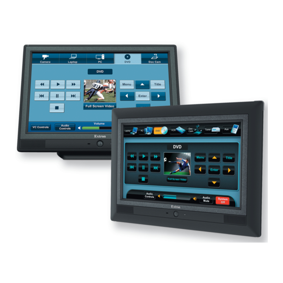
The Extron TLP 1000MV (wall-mounted) and TLP 1000TV (desk-mounted) TouchLink
configuration and control for a range of IP Link
have system control functions associated with them and the touch overlay allows you to activate or regulate those functions.
These touchpanels communicate through an Ethernet connection to a configurable IP Link control processor. Video and audio input is
provided by a twisted pair cable connected to an MTP transmitter.
NOTES:
The network output must be connected to a network switch, hub, or router that is connected to an Ethernet LAN or the
•
Internet.
An Extron IP Link control processor must also be connected to the same network. These touchpanels are not compatible with
•
the IP Link Pro control processors. See
Extron strongly recommends that power is provided by a Power over Ethernet (PoE) power supply.
This guide provides basic instructions for experienced installers to mount and perform initial configuration on the TLP 1000 series of
touchpanels. Full instructions and reference material can be found in the TLP 1000MV and TLP 1000TV User Guide, which is available
at www.extron.com.
Front Panel Features
A A A
B B B
C C C
Extron TLP 1000MV
A
Motion Sensor — when no motion has been detected for a user-defined period of time, the unit goes into sleep mode. When
motion is detected by the sensor, the screen display is restored and active.
B
Microphone — is located below the LCD screen.
C
Connection status LED — is unlit during normal operation. The LED blinks red if the connection to the IP Link controller is lost.
D
Programmable LEDs — one on each top corner can be programmed to provide system feedback. They light red or green and
can blink or light solid.
E
LCD screen — has a 1024x600 resolution with a touch overlay. Extron software is used to design and configure a graphic user
interface to display buttons, text, or icons, which have user-defined functions associated with them.
F
Speakers — Two speakers placed under the screen, on either side of the panel, provide audible feedback for the user.
G
Light Sensor — (can only be seen from above the unit) monitors ambient light level and adjusts screen brightness.
control systems. Graphic and text objects are displayed on the screen. These objects
®
www.extron.com
G G G
D D D
E E E
F F F
Panels provide simple and versatile
™
for a list of compatible models.
G G G
A A A
B B B
C C C
Extron TLP 1000TV
D D D
E E E
F F F
1
Advertisement
Table of Contents

Related Manuals for Extron electronics TouchLink TLP 1000MV


Summary of Contents for Extron electronics TouchLink TLP 1000MV
- Page 1 TLP 1000MV and TLP 1000TV • Setup Guide Overview The Extron TLP 1000MV (wall-mounted) and TLP 1000TV (desk-mounted) TouchLink Panels provide simple and versatile ™ configuration and control for a range of IP Link control systems. Graphic and text objects are displayed on the screen. These objects ®...
- Page 2 TLP 1000MV and TLP 1000TV • Setup Guide (Continued) TLP 1000MV Reset Buttons and LED The TLP 1000MV Menu button, Reset button, and Reset LED are on the front panel, underneat the front bezel. Use the Extron pry tool to remove the bezel.
- Page 3 Product Category Initial Configuration Before use, configure the touchpanel, using the on-screen menus. Main Sleep timer: 300 Sec Auto Backlight Press the Menu button once. (See TLP 1000MV Reset Buttons and LED Active Volume page 2 for the TLP 1000MV or Rear Panel Features on page 2 for the Down...
- Page 4 For information on safety guidelines, regulatory compliances, EMI/EMF compatibility, accessibility, and related topics, see the on the Extron website. Extron Safety and Regulatory Compliance Guide © 2011 - 2020 Extron Electronics — All rights reserved. www.extron.com All trademarks mentioned are the property of their respective owners.
Need help?
Do you have a question about the TouchLink TLP 1000MV and is the answer not in the manual?
Questions and answers