Advertisement
TLC Pro 526M, 726M and 1026M Series • Setup Guide
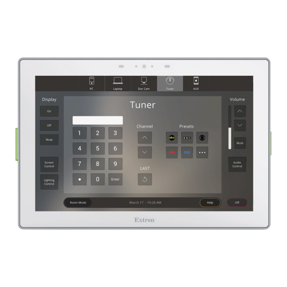
Overview
The Extron TLC Pro 526M, TLC Pro 726M, and TLC Pro 1026M are wall mounted capacitive TouchLink
combine a touchpanel with an internal control processor.
The TLC Pro 526M series touchpanels have a 5-inch screen with a 800x480 resolution and 24-bit color depth.
•
The TLC Pro 726M series touchpanels have a 7-inch screen with a 1024x600 resolution and 24-bit color depth.
•
The TLC Pro 1026M series touchpanels have a 10.1-inch screen with a 1280x800 resolution and 24-bit color depth.
•
Each model has a USB adapter with control ports that can be configured by Extron software. The Touchlink Pro control system
acts as an all-in-one module combining touchpanel asthetics with the internal control processor, eliminating the need for an
external control processor. This guide provides instructions for experienced installers to mount and install these touchpanels.
Setup Checklist
Get Ready
…
Download and install the latest version of the following software:
…
GUI Designer — for designing layouts for Extron TouchLink
Global Configurator
…
Toolbelt — for discovering the control products on the network, for managing core settings, and for upgrading firmware
…
when needed.
NOTE:
All three software programs are available from
…
IP Link Pro Device Drivers — to allow the control ports to interact with the devices they are controlling.
Obtain the following network information from your network administrator:
…
DHCP status (on or off). If DHCP is off, you will also require
…
…
IP address
User name — this can be either admin or user.
…
…
Password — the factory configured passwords are the serial number of the touchpanel (for either admin or user).
NOTE:
The factory configured passwords for all accounts on this device have been set to the device serial number. If the
device is reset, the password reverts to extron. Passwords are case sensitive.
…
Make a note of the touchpanel MAC address (see the rear panel label).
…
Obtain model names and setup information for the devices that will be monitored or controlled by the TouchLink Pro control
system.
…
The TLC Pro Control System comes with a factory-installed Secure Sockets Layer (SSL) security certificate. To install a
different SSL certificate, contact your IT department to obtain the certificate or for instructions on how to obtain one. See
"Secure Sockets Layer (SSL) Certificates" in the TLC Pro 526M, 726M, and 1026M Series User Guide.
IEEE 802.1X authentication is also supported once enabled (see "IEEE 802.1X Certificates" in the TLC Pro 526M, 726M and
…
1026M Series User Guide for details).
Mount and Cable All Devices
…
Connect cables and power cords to the touchpanel and the USB adapter.
ATTENTION:
•
Do not power on the touchpanels until you have read the Attention in the "Rear Panel Features" section of the
TLC Pro 526M, 726M, and 1026M User Guide.
•
Ne branchez pas les écrans tactiles avant d'avoir lu la mise en garde dans la section « Rear Panel Features » du
TLC Pro 526M, 726M, and 1026M User Guide.
…
Connect control ports to the devices they are controlling or monitoring.
Mount the units. There are several mounting options for TLC Pro Control Systems (see
…
unit is mounted, the rear panel is not accessible. Ensure all cables have been connected before mounting.
…
Power on all devices.
Plus and Professional (GC) — for configuring the control system.
®
…
Subnet mask
Pro touchpanels and third party touch interfaces.
®
www.extron.com
.
…
Gateway
Pro control systems that
®
Mounting
on page 7). Once the
1
Advertisement
Table of Contents

Related Manuals for Extron electronics TLC Pro 526M Series


Summary of Contents for Extron electronics TLC Pro 526M Series
- Page 1 ® combine a touchpanel with an internal control processor. The TLC Pro 526M series touchpanels have a 5-inch screen with a 800x480 resolution and 24-bit color depth. • The TLC Pro 726M series touchpanels have a 7-inch screen with a 1024x600 resolution and 24-bit color depth.
-
Page 2: Front Panel Features
Light sensor — Monitors ambient light level and adjusts screen brightness. Capacitive touchscreen — The TLC Pro 526M series has a 5-inch screen with a 800x480 resolution • The TLC Pro 726M series has a 7-inch screen with a 1024x600 resolution •... -
Page 3: Product Category
Product Category Rear Panel Features NOTES: • The panels in figure 2 are for illustration only and are not to the same scale. • For clarity, the first three rear panels in figure 2 are shown with the USB adapter removed. •... - Page 4 TLC Pro 526M, 726M, and 1026M Series • Setup Guide (Continued) Menu Button (see figure 2 on the previous page)— Activates the setup menu (see Setup Menu on page 10). Reset Button — Pressing the Reset button allows the unit to be reset in any of four different modes and can also be used to toggle between enabling and disabling the DHCP client (for an overview, see Reset Modes: a Brief Summary on page 9).
- Page 5 Product Category Control Ports — Touchpanel Digital Input Monitoring Port This port monitors digital input from external devices. Connect a two wires as follows: Ground Control Signal Digital Input Monitoring Port Figure 5. Pin 1 = signal • Pin 2 (G) = ground. •...
- Page 6 TLC Pro 526M, 726M, and 1026M Series • Setup Guide (Continued) Contact closure The contact closure port is used to monitor switches, sensors, or similar devices and trigger events in response to changes to the monitored device. Insert the wires from the monitored device into the contact closure port. A 1k ohm pull-up resistor in a TTL (5 VDC) circuit senses the contact closure.
- Page 7 Product Category Relays There are two relay ports, which share a common ground. These ports may be used to control any equipment as long as the contact specifications of a total of 24 V at 1 A are not exceeded for each port. These relays are normally open by default. When activated, the open contacts close.
- Page 8 TLC Pro 526M, 726M, and 1026M Series • Setup Guide (Continued) With a wall box Figure 13 shows the TLC Pro 726M. Installation for the TLC Pro 526M or TLC Pro 1026M is very similar. Install a junction box or wall box (see figure 13, ), following the instructions provided by the manufacturer.
- Page 9 Allow adequate space to accommodate the USB adapter: • For the TLC Pro 526M series, allow a minimum of 1.00" (26 mm) behind the mounting plate. • For the TLC Pro 726M series, allow a minimum of 1.37" (35 mm) behind the mounting plate.
-
Page 10: Setup Menu
Extron Safety and Regulatory Compliance Guide on the Extron website. www.extron.com © 2019 Extron Electronics — All rights reserved. All trademarks mentioned are the property of their respective owners. 68-3385-50 Rev. A Worldwide Headquarters: Extron USA West, 1025 E. Ball Road, Anaheim, CA 92805, 800.633.9876...
Need help?
Do you have a question about the TLC Pro 526M Series and is the answer not in the manual?
Questions and answers