Mitsubishi Electric MELSEC-L SERIES Basic User Manual
Melsec-l ethernet interface module
Hide thumbs
Also See for MELSEC-L SERIES:
- User manual (168 pages) ,
- Programming manual (196 pages) ,
- Safety manuallines (54 pages)
Table of Contents
Advertisement
Quick Links
Advertisement
Table of Contents
Troubleshooting

Related Manuals for Mitsubishi Electric MELSEC-L SERIES


Summary of Contents for Mitsubishi Electric MELSEC-L SERIES
- Page 1 MELSEC-L Ethernet Interface Module User's Manual (Basic) -LJ71E71-100...
-
Page 3: Safety Precautions
SAFETY PRECAUTIONS (Read these precautions before using this product.) Before using this product, please read this manual and the relevant manuals carefully and pay full attention to safety to handle the product correctly. In this manual, the safety precautions are classified into two levels: " WARNING"... - Page 4 [Design Precautions] WARNING ● For the operating status of each station after a communication failure, refer to relevant manuals for each network. Incorrect output or malfunction due to a communication failure may result in an accident. ● To prevent the malfunction of the programmable controller system due to harmful e-mails, take preventive measures (such as antivirus measures) so that the mail server for this module does not receive harmful e-mails.
- Page 5 ● Use the programmable controller in an environment that meets the general specifications in the Safety Guidelines included with the MELSEC-L series CPU module. Failure to do so may result in electric shock, fire, malfunction, or damage to or deterioration of the product.
- Page 6 [Operating Precautions] CAUTION ● When changing data and operating status, and modifying program of the running programmable controller from a personal computer connected to an intelligent function module, read relevant manuals carefully and ensure the safety before operation. Incorrect change or modification may cause system malfunction, damage to the machines, or accidents.
-
Page 7: Conditions Of Use For The Product
CONDITIONS OF USE FOR THE PRODUCT (1) Mitsubishi programmable controller ("the PRODUCT") shall be used in conditions; i) where any problem, fault or failure occurring in the PRODUCT, if any, shall not lead to any major or serious accident; ii) where the backup and fail-safe function are systematically or automatically provided outside of the PRODUCT for the case of any problem, fault or failure occurring in the PRODUCT. -
Page 8: Introduction
INTRODUCTION Thank you for purchasing the Mitsubishi MELSEC-L series programmable controllers. This manual describes the operating procedure, system configuration, parameter settings, functions, programming, and troubleshooting of the LJ71E71-100 Ethernet interface module (hereafter referred to as E71). Before using this product, please read this manual and the relevant manuals carefully and develop familiarity with the functions and performance of the MELSEC-L series programmable controller to handle the product correctly. -
Page 9: Relevant Manuals
RELEVANT MANUALS The manuals related to this product are listed below. Please place an order as needed. (1) E71 relevant manual Manual name Description <manual number (model code)> E-mail function, communication function (communications via CC-Link IE Controller Network, CC-Link IE Field Network, MELSEC-Q/L Ethernet Interface Module User's Manual (Application) MELSECNET/H, or MELSECNET/10, and communications by <SH-080010, 13JL89>... -
Page 10: Table Of Contents
CONTENTS CONTENTS SAFETY PRECAUTIONS ............. 1 CONDITIONS OF USE FOR THE PRODUCT . - Page 11 7.2.3 Active open procedure ............75 7.2.4 Passive open procedure .
- Page 12 12.6 Data Format ............. . 133 12.6.1 Header .
- Page 13 14.4.4 Differences in functions according to the remote password check status (enabled/disabled) ............... .186 14.4.5 Precautions .
- Page 14 16.6.12 An e-mail cannot be sent........... .255 16.6.13 An e-mail cannot be received.
-
Page 15: Manual Page Organization
MANUAL PAGE ORGANIZATION In this manual, pages are organized and the symbols are used as shown below. The following illustration is for explanation purpose only, and should not be referred to as an actual documentation. "" is used for window names and items. - Page 16 Pages describing instructions are organized as shown below. The following illustration is for explanation purpose only, and should not be referred to as an actual documentation. Instruction name Execution condition of the instruction Structure of the instruction in the ladder mode A device with applicable to the instruction.
- Page 17 For details on each device, refer to the following. User's manual (function explanation, program fundamentals) for the CPU module used The following data types can be used. Data type Description Bit data or the start number of bit data BIN 16-bit 16-bit binary data or the start number of word device BIN 32-bit 32-bit binary data or the start number of double-word device...
-
Page 18: Terms
TERMS Unless otherwise specified, this manual uses the following terms. Term Description The abbreviation for Address Resolution Protocol. This protocol is used to obtain the MAC address of Ethernet from an IP address. A memory in an intelligent function module, where data (such as setting values and monitoring Buffer memory values) exchanged with a CPU module are stored An address that indicates the storage location of data assigned to the buffer memory in an... - Page 19 Term Description A function of GX Works2. Predefined protocol support function This function sets protocols appropriate to each external device and reads/writes protocol setting data from/to the flash ROM of the E71. Programming tool Another term for GX Works2 READ The abbreviation for JP.READ and GP.READ RECV The abbreviation for JP.RECV and GP.RECV...
-
Page 20: Packing List
PACKING LIST The following items are included in the package of this product. Before use, check that all the items are included. LJ71E71-100 LJ71E71-100 Before Using the Product... -
Page 21: Chapter 1 Features
CHAPTER 1 FEATURES CHAPTER 1 FEATURES An Ethernet module (hereafter abbreviated as E71) is an interface module on the programmable controller side for connecting a programmable controller system to the host system, such as a personal computer and a workstation, over Ethernet. - Page 22 (1) Connection with MELSOFT products and a GOT In Ethernet, a programming tool can create programming of a programmable controller and monitor a programmable controller (MELSOFT connection), and the GOT can monitor and test a programmable controller. Remote operations making full use of the Ethernet capability, long-distance connectivity and high-speed communications, are achieved.
- Page 23 CHAPTER 1 FEATURES (4) Data communications using the predefined protocol (predefined protocol support function) Registering protocol data in advance using GX Works2 allows communications by executing only an ECPRTCL instruction program. In addition, the protocol setting required to communicate with the connected device, such as a measuring instrument or a bar code reader, can be configured easily using the Predefined Protocol Support Function of GX Works2.
- Page 24 (5) Exchange of data with connected devices (communications using a fixed buffer and random access buffer) (a) Communications using a fixed buffer Up to 1K-word data can be exchanged among programmable controllers or between a programmable controller and the host system. While MC protocol communications are passive, communications using a fixed buffer are an active protocol.
- Page 25 CHAPTER 1 FEATURES (8) E-mail sending/receiving (e-mail function) This function sends and receives e-mails to and from a connected device in a remote location via the Internet. For details, refer to the following. MELSEC-Q/L Ethernet Interface Module User's Manual (Application) (a) E-mail sending/receiving through the CPU module The following data can be sent and received using the MSEND/MRECV instructions.
- Page 26 (9) Data sending/receiving using the Web function The system administrator can monitor a CPU module in a remote location via the Internet using a Web browser. For details, refer to the following. MELSEC-Q/L Ethernet Interface Module User's Manual (Web function) HTTP MC protocol header...
-
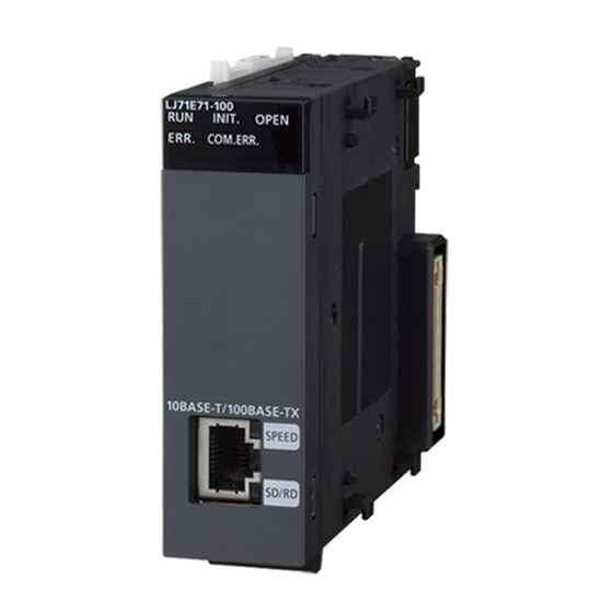
Page 27: Chapter 2 Part Names
CHAPTER 2 PART NAMES CHAPTER 2 PART NAMES This chapter describes the E71 parts. Name Application Module joint lever A lever to fix modules Indicates operating status. In normal operation An error has occurred. ( Page 242, Section 16.4.1) ... - Page 28 Name Application Indicates a transmission speed. SPEED 100Mbps 10Mbps or a cable not connected Indicates data communication status. Data communications in progress SD/RD Data not sent or not received ( Page 243, Section 16.4.3) 10BASE-T/100BASE-TX A connector to connect an E71 to the 10BASE-T or 100BASE-TX network (An E71 judges whether communication connector to connect to the 10BASE-T or 100BASE-TX network based on the hub.) (RJ45)
-
Page 29: Chapter 3 Specifications
CHAPTER 3 SPECIFICATIONS CHAPTER 3 SPECIFICATIONS This chapter describes the performance specifications, functions, CPU module I/O signals, and buffer memory areas of an E71. General Specifications For the general specifications of an E71, refer to the following. "Safety Guidelines", the manual included with the CPU module Performance Specifications The following table lists the performance specifications of an E71. - Page 30 Specifications Item LJ71E71-100 100BASE-TX 10BASE-T 6k words 1 Attachment Data size Main text 960 words 1 When sending: Send either a file as attachment or main text (select one). Data transfer method When receiving: Receive a file as attachment. Subject Us-ASCII format or ISO-2022-JP (Base64) Attachment format...
-
Page 31: Function List
CHAPTER 3 SPECIFICATIONS Function List This section lists the E71 functions. 3.3.1 Function list The following table lists the functions of the E71. (1) Basic functions The following table lists the basic E71 functions explained in this manual. Function Description Reference An E71 can be connected with MELSOFT products, such as Connecting with MELSOFT products and a GOT... - Page 32 Function Description Reference If different stations in the same network use the same IP IP address in use detection function Page 192, Section 14.6 address, the address in use can be detected. Whether a connected device is normally operating after a Alive check function Page 194, Section 14.7 connection is established (open process) can be checked.
-
Page 33: Use With Other Functions
CHAPTER 3 SPECIFICATIONS 3.3.2 Use with other functions The following table lists the relationships between functions that can be used together. : Available, : Not available or this function does not correspond to the functions in the "Communication function" column. CC-Link IE Controller Network, Communication... -
Page 34: List Of I/O Signals
List of I/O Signals The following table lists the I/O signals for an E71. The I/O signal assignment of when the start I/O number of an E71 is 0000 is listed below. Device Device Signal name Signal name number number For fixed buffer communication of connection No.1 (ON: Connection No.1 (ON: At sending request or reception complete Sending normal completion or reception completion, OFF: -) - Page 35 CHAPTER 3 SPECIFICATIONS Device Device Signal name Signal name number number Initial normal completion signal Initial request signal (ON: Normal completion, OFF: -) (ON: At request, OFF: -) Initial abnormal end signal Use prohibited (ON: Abnormal end, OFF: -) Use prohibited Use prohibited COM.ERR.
-
Page 36: Buffer Memory
Buffer Memory This section describes the E71 buffer memory. 3.5.1 Configuration of the buffer memory This section describes a buffer memory configuration. (1) Buffer memory address configuration A buffer memory area consists of 16 bits per address. b15 b14 b13 b12 b11 b10 b8 b7 b6 b5 b4 b3 b2 b1 b0 (2) Buffer memory area configuration Buffer memory consists of user areas and system areas. -
Page 37: List Of Buffer Memory Addresses
CHAPTER 3 SPECIFICATIONS 3.5.2 List of buffer memory addresses The following table lists the buffer memory addresses of an E71. Address Programming Application Name Initial value tool setting Decimal applicability (Hexadecimal) 0 and 1 C00001FE Own station E71 IP address and 1 2 and 3 ... - Page 38 Address Programming Application Name Initial value tool setting Decimal applicability (Hexadecimal) TCP Maximum Segment Transmission setting area • 0 : Enable TCP Maximum Segment Size Option transmission 8000 • 8000 : Disable TCP Maximum Segment Size Option transmission Re-initialization makes the set value effective. Communication condition setting (Ethernet Operation Setting) area Communication data code setting (b1) •...
- Page 39 CHAPTER 3 SPECIFICATIONS Address Programming Application Name Initial value tool setting Decimal applicability (Hexadecimal) Connection No.1 Usage of fixed buffer (b0) • 0: For sending, or communications using a fixed buffer are not performed • 1: For receiving Destination existence confirmation (b1) •...
- Page 40 Address Programming Application Name Initial value tool setting Decimal applicability (Hexadecimal) 61 to 67 Connection No.4 (The bit configuration is the same as Connection No.1.) to 43 68 to 74 Connection No.5 (The bit configuration is the same as Connection No.1.) to 4A Communica 75 to 81...
- Page 41 CHAPTER 3 SPECIFICATIONS Address Programming Application Name Initial value tool setting Decimal applicability (Hexadecimal) 130 to 139 Connection No.2 (The bit configuration is the same as Connection No.1.) to 8B 140 to 149 Connection No.3 (The bit configuration is the same as Connection No.1.) to 95 150 to 159 Connection No.4 (The bit configuration is the same as Connection No.1.)
- Page 42 Address Programming Application Name Initial value tool setting Decimal applicability (Hexadecimal) Status of settings with a programming tool Communication data code setting (b1) • 0: Communications in a binary code • 1: Communications in an ASCII code Initial/open method setting (b2) •...
- Page 43 CHAPTER 3 SPECIFICATIONS Address Programming Application Name Initial value tool setting Decimal applicability (Hexadecimal) Error code/end code Subheader Command code Connection No. Error log block Own station port No. 234 and 235 Destination IP address and EB Destination Port No.
- Page 44 Address Programming Application Name Initial value tool setting Decimal applicability (Hexadecimal) 376 and 377 Received IP packet count (178 and 179 378 and 379 Received IP packet count discarded (17A and 17B due to sumcheck error 380 and 381 ...
- Page 45 CHAPTER 3 SPECIFICATIONS Address Programming Application Name Initial value tool setting Decimal applicability (Hexadecimal) 512 and 513 Sub-net mask (200 and 201 514 and 515 Default router IP address (202 and 203 Number of registered routers (204 517 and 518 ...
- Page 46 Address Programming Application Name Initial value tool setting Decimal applicability (Hexadecimal) 944 to 949 FTP login name "LJ71E71" (3B0 to 3B5 950 to 953 Password "LJ71E71" (3B6 to 3B9 FTP setting area Command input monitoring timer (3BA ...
- Page 47 CHAPTER 3 SPECIFICATIONS Address Programming Application Name Initial value tool setting Decimal applicability (Hexadecimal) Open completion signal • 0: Open incomplete • 1: Open completed 20480 Connection No.1 (b0) (5000 Connection No.2 (b1) Connection No.16 (b15) 20481 Connection System area ...
- Page 48 Address Programming Application Name Initial value tool setting Decimal applicability (Hexadecimal) Remote password mismatch notification accumulated 20592 count designation (For user open port) (5070 • 0: No designation • 1 or higher: Notification accumulated count Remote password mismatch notification accumulated count designation (For auto-open UDP port, MELSOFT 20593 application transmission port (TCP/ UDP) and FTP...
- Page 49 CHAPTER 3 SPECIFICATIONS Address Programming Application Name Initial value tool setting Decimal applicability (Hexadecimal) 20644 to 20648 Connection No.11 (The bit configuration is the same as Connection No.1.) (50A4 to 50A8 20649 to 20653 Connection No.12 (The bit configuration is the same as Connection No.1.) (50A9 to 50AD 20654 to 20658...
- Page 50 Address Programming Application Name Initial value tool setting Decimal applicability (Hexadecimal) 20765 to 20771 Error log block 4 (The bit configuration is the same as Error log block 1.) (511D to 5123 20772 to 20778 Error log block 5 (The bit configuration is the same as Error log block 1.) (5124 to 512A 20779 to 20785...
- Page 51 CHAPTER 3 SPECIFICATIONS Address Programming Application Name Initial value tool setting Decimal applicability (Hexadecimal) 21280 to 21283 System area (5320 to 5323 21284 Protocol No. (5324 21285 Setting type (5325 Protocol setting data error information 21286 ...
- Page 52 Address Programming Application Name Initial value tool setting Decimal applicability (Hexadecimal) 21856 to 21875 Connection No.9 (The bit configuration is the same as Connection No.1.) (5560 to 5573 21876 to 21895 Connection No.10 (The bit configuration is the same as Connection No.1.) (5574 to 5587 21896 to 21915...
- Page 53 CHAPTER 3 SPECIFICATIONS Address Programming Application Name Initial value tool setting Decimal applicability (Hexadecimal) 22560 Own station port No. (5820 22561 and 22562 Destination IP address (5821 to 5822 22563 Destination Port No. (5823 22564 Open error code (5824 22565 Connection...
- Page 54 Address Programming Application Name Initial value tool setting Decimal applicability (Hexadecimal) 22640 Number of mails remaining on the server (5870 22641 Dedicated instruction normal completion count (5871 22642 Dedicated instruction abnormal end count (5872 22643 Normal receiving count (5873 22644 ...
- Page 55 CHAPTER 3 SPECIFICATIONS Address Programming Application Name Initial value tool setting Decimal applicability (Hexadecimal) 22693 to 22736 Error log block 2 (The bit configuration is the same as Error log block 1.) (58A5 to 58D0 22737 to 22780 Error log block 3 (The bit configuration is the same as Error log block 1.) (58D1 to 58FC 22781 to 22824...
- Page 56 Address Programming Application Name Initial value tool setting Decimal applicability (Hexadecimal) 23361 Error code (5B41 23362 Command code (5B42 23363 to 23370 Error log block (5B43 to 5B4A 23371 to 23374 Date (5B4B to 5B4E 23375 to 23404 ...
-
Page 57: Chapter 4 Procedures Before Operation
CHAPTER 4 PROCEDURES BEFORE OPERATION CHAPTER 4 PROCEDURES BEFORE OPERATION This chapter describes how to connect an E71 to Ethernet. For how to communicate with connected devices after the E71 is connected, refer to the communication procedure. ( Page 64, CHAPTER 7) Checkbox System consideration Page 27, CHAPTER 3,... - Page 58 Memo...
-
Page 59: Chapter 5 System Configuration
CHAPTER 5 SYSTEM CONFIGURATION CHAPTER 5 SYSTEM CONFIGURATION Overall System Configuration The following is a system configuration example of when using an E71. Display unit (optional) I/O modules Power supply module CPU module intelligent function modules END cover... -
Page 60: Network Components
Network Components This section describes the devices used for Ethernet. Connected device An E71 determines whether to use 100BASE-TX or 10BASE-T and the full-duplex or half-duplex transmission mode according to the hub. For connection to a hub without the automatic negotiation function, set the half-duplex mode on the hub side. - Page 61 CHAPTER 5 SYSTEM CONFIGURATION (2) 10BASE-T connection To configure a system for 10BASE-T connection, use devices that meet the IEEE 802.3 10BASE-T standards. Configuration device Description Straight cable Unshielded twisted pair cable (UTP) or shielded A Category 3, 4, or 5 straight cable or cross cable is usable. twisted pair cable (STP) Cross cable ...
-
Page 62: Applicable Systems
Applicable Systems This section describes MELSEC-L series systems that include an E71. (1) Applicable CPU modules and the number of connectable modules An E71 can be connected to an LCPU with an serial number (first five digits) of 14112 or later. -
Page 63: Chapter 6 Installation And Wiring
CHAPTER 6 INSTALLATION AND WIRING CHAPTER 6 INSTALLATION AND WIRING This chapter describes installation and wiring of the E71. Installation This section describes installation of the E71. (1) Installation method For the module installation environment and position, refer to the following. MELSEC-L CPU Module User's Manual (Hardware Design, Maintenance and Inspection) (2) Handling precautions... -
Page 64: Wiring
Wiring This section describes Ethernet cable wiring and wiring precautions. For a network configuration and cables and hubs used, refer to "SYSTEM CONFIGURATION". ( Page 57, CHAPTER 5) (1) Ethernet cable connection The following is how to connect and disconnect an Ethernet cable. (a) Connecting the cable Power off the E71 and the connected device. - Page 65 CHAPTER 6 INSTALLATION AND WIRING (2) Precautions This section describes wiring precautions. (a) Handling Place the Ethernet cable in a duct or clamp them. If not, dangling cable may swing or inadvertently be pulled, resulting in damage to the module or cables or malfunction due to poor contact. Do not touch the core of the cable-side or module-side connector, and protect it from dirt or dust.
-
Page 66: Chapter 7 Communication Procedure
CHAPTER 7 COMMUNICATION PROCEDURE This chapter describes the procedure for communicating with connected devices after the E71 is connected to Ethernet. For the procedure for connecting the E71 to Ethernet, refer to "PROCEDURES BEFORE OPERATION". Continued from PROCEDURES BEFORE OPERATION Page 55, CHAPTER 4) Parameter settings Page 65, Section 7.1,... -
Page 67: Setting Parameters Required For Communications
CHAPTER 7 COMMUNICATION PROCEDURE Setting Parameters Required for Communications This section describes how to set parameters to communicate between the E71 and connected devices. 7.1.1 Parameter list The following table lists parameters set through a programming tool. Item Description Reference Network Type Start I/O No. -
Page 68: Basic Setting
7.1.2 Basic setting Set items, such as a network number and station number. Project window [Parameter] [Network Parameter] [Ethernet/CC IE Field] Select "Ethernet" under "Network Type". Item Description Setting range Network Type Select "Ethernet". Within the number of I/O points of the Start I/O No. -
Page 69: Ethernet Operation Setting
CHAPTER 7 COMMUNICATION PROCEDURE 7.1.3 Ethernet Operation Setting Configure the settings, such as an IP address, to connect the E71 to Ethernet. Project window [Parameter] [Network Parameter] [Ethernet/CC IE Field] Select "Ethernet" under "Network Type". button Item Description Setting range •... - Page 70 (1) Initial Timing This setting configures the open timing of the connection where "TCP" (Passive open) or "UDP" has been selected under "Open System" in the open setting. ( Page 69, Section 7.1.4) (a) Do not wait for OPEN (Communications impossible at STOP time) Connections are opened or closed using a program.
-
Page 71: Open Setting
CHAPTER 7 COMMUNICATION PROCEDURE 7.1.4 Open Setting Configure settings to open connections for data communications with connected devices. Project window [Parameter] [Network Parameter] [Ethernet/CC IE Field] Select "Ethernet" under "Network Type". button Item Description Setting range IP Address/Port No. Input •... - Page 72 Item Description Setting range • DEC: 0.0.0.0 to 255.255.255.255 Destination IP Address Set the IP address of the connected device. • HEX: 00.00.00.00 to FF.FF.FF.FF • DEC: 1 to 65535 Destination Port No. Set port numbers for connections of connected devices. •...
- Page 73 CHAPTER 7 COMMUNICATION PROCEDURE ● Note the following points when setting port numbers. : Can be set, : Cannot be set Communication protocol Connection status Description TCP/IP UDP/IP Connected device When connecting multiple connected devices, set multiple own station port numbers. Connected device Connected device When connecting multiple connected devices, set a single...
-
Page 74: Tcp/Ip Communications
TCP/IP Communications This section describes TCP/IP communications. 7.2.1 Establishing a connection TCP/IP communications require establishing connections between communication devices. When the server-side device is in standby status after performing a Passive open process, a connection is established after the client-side device issues an open request (Active open process) to the server and a response is received. -
Page 75: Communication Process
CHAPTER 7 COMMUNICATION PROCEDURE 7.2.2 Communication process This section describes the process from establishing a connection to terminating communications. Server Client Connected device After the server performs Passive open, it will wait for an open request from the client. Passive open When the client sends Active open request and Open request... - Page 76 ● The corresponding bit of Open completion signal (address: 5000 ) automatically turns off and the communication line is closed in the following situations: • A timeout has occurred in the alive check function. ( Page 194, Section 14.7) • An E71 has received a close request and the ABORT (RST) instruction from a connected device. •...
-
Page 77: Active Open Procedure
CHAPTER 7 COMMUNICATION PROCEDURE 7.2.3 Active open procedure Active open is a connection method that performs an active open process on a connected device in Passive open wait status. The procedure that the E71 performs an Active open process is as follows. For the OPEN/CLOSE instructions, refer to "DEDICATED INSTRUCTIONS". - Page 78 If the E71 sends an SYN and the connected device returns a RST, Open abnormal detection signal (X18) turns on immediately and the open process terminates. (Open abnormal end) If an ACK and a FIN are not returned within the time specified by the TCP end timer value, the E71 forcibly closes the connection (sends a RST).
-
Page 79: Passive Open Procedure
CHAPTER 7 COMMUNICATION PROCEDURE 7.2.4 Passive open procedure The E71 has the following two connection methods for Passive open. Performs a passive open process on connections for all devices connected to the network, Unpassive regardless of the IP address and port number of the destination device. Performs a passive open process on connections for the connected device specified by the Fullpassive IP address and port number. - Page 80 (2) When "Do not wait for OPEN (Communications impossible at STOP time)" is selected for the Ethernet operation setting Executing the OPEN/CLOSE instructions is required on the E71 to make the E71 enter open/close wait status before receiving an open/close request from the connected device. When the open process is normally completed, data sending and receiving are enabled.
-
Page 81: Udp/Ip Communications
CHAPTER 7 COMMUNICATION PROCEDURE ● Change connection settings before executing the OPEN instruction. ● Once an open process is performed, an open request cannot be canceled before the open process is completed. Perform a close process (Execute the CLOSE instruction) after the open process is completed. UDP/IP Communications This section describes UDP/IP communications. -
Page 82: Open Procedure
7.3.2 Open procedure The open/close processes are performed by the procedures described below, according to the Ethernet operation setting. (1) When "Always wait for OPEN (Communication possible at STOP time)" is selected for the Ethernet operation setting After the E71-connected station is started up, the connection in UDP/IP communications automatically opens and data sending/receiving are enabled. - Page 83 CHAPTER 7 COMMUNICATION PROCEDURE (2) When "Do not wait for OPEN (Communications impossible at STOP time)" is selected for the Ethernet operation setting Executing the OPEN/CLOSE instructions is required on the E71 to make the E71 enter open/close wait status open/close wait status before receiving an open/close request from the connected device.
-
Page 84: Chapter 8 Connecting Melsoft Products And A Got
CHAPTER 8 CONNECTING MELSOFT PRODUCTS AND A GOT This chapter describes the connection of the E71 with MELSOFT products (such as a programming tool and MX Component) and the GOT. Applications This section describes applications according to a connection type. (1) Programming and monitoring over Ethernet In Ethernet, a programming tool can create programming of a programmable controller and monitor a programmable controller (MELSOFT connection), and the GOT can monitor and test a programmable controller. -
Page 85: Data Communication Procedure
CHAPTER 8 CONNECTING MELSOFT PRODUCTS AND A GOT Data Communication Procedure This section describes the data communication procedure in the MELSOFT connection. Connecting the E71 and a personal computer (programming tool) Write the parameter settings ( Page 69, Section 7.1.4) in the CPU module. To connect multiple products in the TCP/IP communications, set the connection for the second product or more in the open setting. - Page 86 Select "Ethernet Module" under "PLC side I/F" and double-click the item. The window shown to left appears. Set the station number and the IP address according to the network parameters. Set "Other Station Setting" and "Network Communication Route" when required. A Passive open process is performed on all the MELSOFT products connected to the network.
-
Page 87: Chapter 9 Mc Protocol Communications
CHAPTER 9 MC PROTOCOL COMMUNICATIONS CHAPTER 9 MC PROTOCOL COMMUNICATIONS Using MC protocol communications, connected devices that can send and receive data in accordance with the MC protocol can access a CPU module. Because an E71 processes and sends/receives data based on commands from connected devices, no programs for data communications are required on the programmable controller side. -
Page 88: Communication Structure
Communication Structure When a connected device sends a message to an E71 in the MC protocol message format, the E71 performs the process according to the message. During communications, a CPU module including the E71 operates as a server, and the connected device (a personal computer or other terminals) operates as a client. Based on the command message received from the client, the server (the E71) automatically sends an appropriate response message. -
Page 89: Data Communication Procedure
CHAPTER 9 MC PROTOCOL COMMUNICATIONS Data Communication Procedure The following is a data communication procedure for MC protocol communications. Set the parameters. ( Page 88, Section 9.4) Perform the open process and establish a connection between the E71 and the connected device. Page 72, Section 7.2, Page 79, Section 7.3) Once the connection is established, the connected device sends an MC protocol message. -
Page 90: Parameter Setting
Parameter Setting Set the following parameters for MC protocol communications. • Basic setting ( Page 66, Section 7.1.2) • Ethernet operation setting ( Page 67, Section 7.1.3) • Open setting ( Page 69, Section 7.1.4) Item Description Setting range Fixed Buffer Select the communication method for communications using a fixed buffer. -
Page 91: Chapter 10 Slmp Communications
CHAPTER 10 SLMP COMMUNICATIONS CHAPTER 10 SLMP COMMUNICATIONS SLMP is a protocol that enables connected devices to access SLMP supporting devices over Ethernet. SLMP communications are available among devices that can receive/send messages in the SLMP control procedure. This function is available only in the E71 with the serial number (first five digits) of "15042" or later. For SLMP communications, refer to the following. -
Page 92: Communication Structure
10.2 Communication Structure When a connected device sends a message to an E71 in the SLMP message format, the E71 performs the process according to the message. During communications, a CPU module including the E71 operates as a server, and the connected device (a personal computer or other terminals) operates as a client. -
Page 93: Data Communication Procedure
CHAPTER 10 SLMP COMMUNICATIONS 10.3 Data Communication Procedure The following is a data communication procedure for SLMP communications. Set the parameters. ( Page 92, Section 10.4) Perform the open process and establish a connection between the E71 and the connected device. Page 72, Section 7.2, Page 79, Section 7.3) Once the connection is established, the connected device sends an SLMP message. -
Page 94: Parameter Setting
10.4 Parameter Setting Set the following parameters for SLMP communications. • Basic setting ( Page 66, Section 7.1.2) • Ethernet operation setting ( Page 67, Section 7.1.3) • Open setting ( Page 69, Section 7.1.4) Item Description Setting range Fixed Buffer Select the communication method for communications using a fixed buffer. -
Page 95: Available Command List
CHAPTER 10 SLMP COMMUNICATIONS 10.5 Available command list The following table lists the commands that can be executed from a connected device to the E71. The part in the Subcommand column varies depending on the specified device. For details on each command, refer to the following. SLMP Reference Manual Item Command... - Page 96 Item Command Subcommand Description Type Operation Read Directory/File 1810 0000 Reads file list information from the CPU module where an E71 is connected. Reads the file number of the specified file from the CPU module where an E71 is Search Directory/File 1811 0000 connected.
-
Page 97: Chapter 11 Data Communications Using The Predefined Protocol
CHAPTER 11 DATA COMMUNICATIONS USING THE PREDEFINED PROTOCOL CHAPTER 11 DATA COMMUNICATIONS USING THE PREDEFINED PROTOCOL Data can be transferred between a connected device and the CPU module with a protocol appropriate to the connected device (such as a measuring instrument or a bar code reader). Device or buffer memory data can be taken into communication packets, and thereby this protocol communications are suitable for data that may change in each communication. - Page 98 ● The followings are the maximum numbers of protocols and packets that can be registered. • Protocols: Up to 128 • Packets: Up to 256 • Packet data area size: Up to 12288 bytes If once the number of packets reaches the upper limit, protocols cannot be added even though the number of protocols has not reached the upper limit.
-
Page 99: Data Communication Procedure
CHAPTER 11 DATA COMMUNICATIONS USING THE PREDEFINED PROTOCOL 11.1 Data Communication Procedure By using the predefined protocol support function, data can be communicated with the connected device in the following procedure. Display the "Predefined Protocol Support Function" window. [Tool] [Predefined Protocol Support Function] [Ethernet Module...] Create a new file. - Page 100 Set the items required for the data communications. • Set communication parameters in the "Protocol Detailed Setting" window. "Protocol Detailed Setting" window Select a protocol [Edit] [Protocol Detailed Setting...] • Set the configuration of packets to be sent and received in the "Packet Setting"...
- Page 101 CHAPTER 11 DATA COMMUNICATIONS USING THE PREDEFINED PROTOCOL Write the protocol setting data to the flash ROM. [Online] [Write to PLC...] Select a target module and write the protocol setting data to the flash ROM. When the initial process is not completed, the protocol setting data cannot be written to the flash ROM. Before writing the data, set the network parameters and check that the initial process is completed.
-
Page 102: Communication Type Of Protocols
11.2 Communication Type of Protocols Receive and send packets from/to the connected device for the process execution are registered in a protocol. Packet elements set using the predefined protocol support function correspond to the data part of the send/receive packets. The following shows an example of packet configuration. -
Page 103: Packet Elements
CHAPTER 11 DATA COMMUNICATIONS USING THE PREDEFINED PROTOCOL 11.3 Packet Elements A packet consists of packet elements. Up to 32 elements can be placed in a packet, and the maximum data length is 2046 bytes per packet. The following shows the details of the packet elements. For examples of packet element data, refer to Page 346, Appendix 8.3. - Page 104 (2) Length This element is used when an element indicating the data length is included in a packet. • When sending: The data length of the specified range is calculated and the result is added to a send packet. • When receiving: The data (setting value) corresponds to the Length in the receive data is verified as the data length of the specified range.
- Page 105 CHAPTER 11 DATA COMMUNICATIONS USING THE PREDEFINED PROTOCOL ● Multiple Length elements can be placed in a packet. ● When there is no element other than a Length element, an element error occurs. (To use a Length element, one or more element(s) other than Length is/are required.) ●...
- Page 106 (3) Non-conversion Variable This element is used to send data in the device memory of a CPU module or buffer memory as a part of a send packet, or to store a part of a receive packet to the device memory of a CPU module device or buffer memory. The following table lists the items.
- Page 107 CHAPTER 11 DATA COMMUNICATIONS USING THE PREDEFINED PROTOCOL Item Description Specify a start device to store variable value. Available devices are as follows: *1*2 • Internal user Input relay (X) Output relay (Y) Internal relay (M) Latch relay (L) Data Storage Area Link relay (B) Specification Data register (D)
- Page 108 (b) When "Fixed Length/Variable Length" is "Variable Length" An area starting from the device number which is specified in the "Element Setting" window +1 is considered as the data storage area. The data storage area to be occupied varies depending on the setting of "Unit of Stored Data". •...
- Page 109 CHAPTER 11 DATA COMMUNICATIONS USING THE PREDEFINED PROTOCOL (4) Non-verified Reception This element is used when receive data include unnecessary data. The E71 skips characters as many as the specified number if a receive packet includes a Non-verified Reception. The following table lists the items. Item Description Remark...
-
Page 110: Execution Condition Of Predefined Protocol Communication
11.4 Execution Condition of Predefined Protocol Communication Communications using the predefined protocol can be executed when Predefined protocol ready (X1D) is on. This section describes the operations of Predefined protocol ready (X1D). (1) When the power supply is on or reset The E71 checks the written protocol setting data when the power supply is on or reset. - Page 111 CHAPTER 11 DATA COMMUNICATIONS USING THE PREDEFINED PROTOCOL (b) If an error has occurred in the protocol setting data Power on/reset Check result error Checking the protocol setting data X1D stays off. Predefined protocol ready (X1D) Protocol setting data check area The error details are stored.
- Page 112 (b) If an error has occurred in the protocol setting data Start to write the protocol setting data. Check result error Writing the protocol Checking the protocol setting data setting data X1D turns on when the protocol setting data has X1D turns off.
-
Page 113: Example Of Predefined Protocol Communications
CHAPTER 11 DATA COMMUNICATIONS USING THE PREDEFINED PROTOCOL 11.5 Example of Predefined Protocol Communications This section describes an example of communications using the predefined protocol under the following system configuration. 11.5.1 System configuration example (1) System configuration LCPU-1 LCPU-2 GX Works2 (192.0.1.100) (192.0.1.101) Ethernet... -
Page 114: Parameter Setting
11.5.2 Parameter Setting (1) Sending side (LCPU-1 side) The following is an example of the parameter settings of the sending side (LCPU-1 side). (a) Basic setting The following is an example of the basic setting. (b) Ethernet operation setting The following is an example of the Ethernet operation setting. - Page 115 CHAPTER 11 DATA COMMUNICATIONS USING THE PREDEFINED PROTOCOL (c) Open setting The following is an example of the open setting.
- Page 116 (d) Protocol setting data The value in D100 to D109 of the destination station can be read by using SLMP (Device Read) command in the Predefined Protocol Library. The followings are setting examples of the protocol setting data using the Predefined Protocol Support Function.
- Page 117 CHAPTER 11 DATA COMMUNICATIONS USING THE PREDEFINED PROTOCOL • Receive Packet (Normal response) • Receive Packet (Error response)
- Page 118 (2) Receiving side (LCPU-2 side) The following is an example of the parameter settings of the receiving side (LCPU-2 side). (a) Basic setting The following is an example of the basic setting. (b) Ethernet operation setting...
- Page 119 CHAPTER 11 DATA COMMUNICATIONS USING THE PREDEFINED PROTOCOL (c) Open setting...
-
Page 120: Program Example
11.5.3 Program example The following is a program example that specifies Connection No.1 and executes a protocol by using the ECPRTCL instruction. (1) Sample program (a) Sending side (LCPU-1 side) <<Open process program>> <<Program for predefined protocol communications>>... - Page 121 CHAPTER 11 DATA COMMUNICATIONS USING THE PREDEFINED PROTOCOL <<Close process program>>...
-
Page 122: Chapter 12 Communications Using A Fixed Buffer
CHAPTER 12 COMMUNICATIONS USING A FIXED BUFFER This chapter describes communications using a fixed buffer. 12.1 Applications In communications using a fixed buffer, a programmable controller can actively send data; therefore, data can be sent from the programmable controller to the host system when an error occurs in machine equipment or some other conditions are satisfied. -
Page 123: Communication Structure
CHAPTER 12 COMMUNICATIONS USING A FIXED BUFFER 12.2 Communication Structure This section describes the structure of communications using a fixed buffer. (1) Data flow In communications using a fixed buffer, data is sent/received using dedicated instructions. • Sending data: BUFSND instruction •... - Page 124 ● When changing connected devices, do not use the pairing open or alive check function. ● When "No Procedure" is selected for a connection, the connection is dedicated to "No Procedure" communications using a fixed buffer after the open process is completed. When "Procedure Exist" is selected for a connection, the following data communications can be performed after the open process is completed.
-
Page 125: Data Sending Procedure
CHAPTER 12 COMMUNICATIONS USING A FIXED BUFFER 12.3 Data Sending Procedure This section describes how an E71 sends data to the connected device. (1) Procedure exists The following is the data send process performed in the fixed buffer number 1 area for the connection number 1. Initial process Open process Sending data Receiving a response... - Page 126 (2) No procedure The following is the data send process performed in the fixed buffer number 1 area for the connection number 1. Initial process Open process Sending data Initial normal completion signal X19 Open completion signal (address: 5000H [b0]) BUFSND instruction BUFSND instruction completion device...
-
Page 127: Data Receiving Procedure
CHAPTER 12 COMMUNICATIONS USING A FIXED BUFFER 12.4 Data Receiving Procedure This section describes how an E71 receives data from the connected device. The following methods for receiving data are offered: • Data receiving using the main program (BUFRCV instruction) •... - Page 128 ● The items configured in the open setting become enabled when Open completion signal of an E71 is started up. ● When the buffer memory area that stores Fixed buffer reception status signal is turned off and on, execute the BUFRCV instruction.
- Page 129 CHAPTER 12 COMMUNICATIONS USING A FIXED BUFFER (2) No procedure The following is the receive process performed in the fixed buffer number 1 area for the connection number 1. Receiving data Initial process Open process Initial normal completion signal X19 Open completion signal (address: 5000 [b0])
-
Page 130: Data Receiving Using An Interrupt Program (Bufrcvs Instruction)
12.4.2 Data receiving using an interrupt program (BUFRCVS instruction) A receive process in an interrupt program is performed using the BUFRCVS instruction. An interrupt program is started up when data is received from a connected device, and receive data for a CPU module can be read. The following settings are required to use an interrupt program: ( Page 131, Section 12.5.1) •... - Page 131 CHAPTER 12 COMMUNICATIONS USING A FIXED BUFFER (2) No procedure The following is the receive process performed in the fixed buffer number 2 area for the connection number 2. Initial Open process process Receiving data Initial normal completion signal X19 Open completion signal (address: 5000 [b1])
-
Page 132: Parameter Setting
12.5 Parameter Setting Set the following parameters to perform communications using a fixed buffer. • Basic setting ( Page 66, Section 7.1.2) • Ethernet operation setting ( Page 67, Section 7.1.3) • Open setting ( Page 69, Section 7.1.4) Item Description Setting range Select whether to use the fixed buffer for connection with the connected device for... -
Page 133: Parameter Setting When Using An Interrupt Program
CHAPTER 12 COMMUNICATIONS USING A FIXED BUFFER 12.5.1 Parameter setting when using an interrupt program Configure the parameter setting on a programming tool to start up an interrupt program. CPU module Control <Program> Connection No.1 number Interrupt interrupt pointer Connection No.2 Z.BUFRCVS (SI) No. - Page 134 (2) Interrupt settings The following is a setting example. Project window [Parameter] [Network Parameter] [Ethernet/CC IE Field] Select "Ethernet" under "Network Type". button Item Description Setting range Input Format The input format of each data is decimal number only. Device Code Select a device code.
-
Page 135: Data Format
CHAPTER 12 COMMUNICATIONS USING A FIXED BUFFER 12.6 Data Format Communication data consists of a header and application data. 12.6.1 Header The header for TCP/IP or UDP/IP is used. Because an E71 automatically adds and deletes a header, the user setting is not required. - Page 136 (a) Format • Communications using a binary code Application data area (command message) Maximum of 2 bytes 1017 words 2 bytes Data length Text Communication Subheader request source (command) setting Communication Subheader End code request destination 1 byte 1 byte Application data area (Response) •...
- Page 137 CHAPTER 12 COMMUNICATIONS USING A FIXED BUFFER (b) Subheader Because an E71 automatically adds and deletes a header, the user setting is not required. Command Response Communications using a binary code Subheader Subheader "6" "0" "E" "0" Communications using an ASCII code Subheader Subheader (c) Data length setting...
- Page 138 (d) Text (command) The following is the format of a command/response. • Communications using a binary code Command format Maximum of 1017 words Subheader Data specifying/ storing device for sending/ receiving instructions Data length setting n + 1 n + 2 Send/ n + 3 receive data...
- Page 139 CHAPTER 12 COMMUNICATIONS USING A FIXED BUFFER (e) End codes An error code is stored in the end code added to a response. For the error codes, refer to the error code list. Page 268, Section 16.7.1) End codes are stored in the complete status area (in the control data) of the BUFSND and BUFRCV instructions, as well as the communication status storage area of the buffer memory.
- Page 140 (2) No procedure In the application data for communications in the "No Procedure" control method, the following data code is expressed in a binary code. Communications are performed using a binary code regardless of the communication data code setting. Text (command) Maximum of 2046 bytes In communications in the "No Procedure"...
-
Page 141: Pairing Open
CHAPTER 12 COMMUNICATIONS USING A FIXED BUFFER 12.7 Pairing Open Pairing open is an opening method that connects the own station with the connected device using only one port by pairing the receive and send connections for communications using a fixed buffer. 12.7.1 Applications Enabling the pairing open allows data communications to be performed with two connections by performing the open... -
Page 142: Parameter Setting
12.7.2 Parameter setting The following is the pairing open setting. Item Description Setting range Set "Pairing Open" of the receive connection to "Enable". The next connection is Pairing Open automatically set as a send connection. When "Enable" has been set in "Pairing Open" for a send connection, the following window appears. When the button is selected, the applicable connection becomes a receive connection, and the next connection is automatically set as a send connection. -
Page 143: Broadcast Communications
CHAPTER 12 COMMUNICATIONS USING A FIXED BUFFER 12.8 Broadcast Communications Broadcast communications mean that the same data is sent to all E71-connected stations in the same Ethernet network and to the connected devices without specifying destinations. Broadcast communications can be performed when the following conditions are met. - Page 144 Remark The following is the outline of the internal process of an E71 when data is received in the "No Procedure" control method or by broadcast communications. (The values specified in the buffer memory addresses 0 and 28 to 5F are used for the IP addresses and port numbers of the E71 in the own station as well as those of connected devices.) Data received...
-
Page 145: Parameter Setting
CHAPTER 12 COMMUNICATIONS USING A FIXED BUFFER 12.8.2 Parameter setting The following is the parameter setting for broadcast communications. (1) When sending data The following is the parameter setting for data sending. Item Description Setting range Protocol Select "UDP". ... - Page 146 (2) When receiving data The following is the parameter setting for data receiving. Item Description Setting range Protocol Select "UDP". Fixed Buffer Select "Receive". Fixed Buffer Communication Select "No Procedure". Existence Confirmation Select "No Confirm". Set FFFFFFFF Destination IP Address ...
-
Page 147: Precautions
CHAPTER 12 COMMUNICATIONS USING A FIXED BUFFER 12.8.3 Precautions This section describes the precautions for broadcast communications. (1) Port number To perform broadcast communications, the user needs to determine the port numbers dedicated for data sending/receiving for broadcast communications and specify these port numbers. (2) Size of send/receive data per sending/receiving A maximum of 2046 bytes of data in the application data can be processed per sending/receiving. -
Page 148: Example Of Communications Using A Fixed Buffer
12.9 Example of Communications Using a Fixed Buffer This section describes an example of communications using a fixed buffer in the "Procedure Exist" control method between an E71 and the connected device. 12.9.1 System configuration The following system configuration is used for explanation purpose. LCPU-1 LCPU-2 (10.97.85.222) - Page 149 CHAPTER 12 COMMUNICATIONS USING A FIXED BUFFER (b) Ethernet operation setting The following is an example of the Ethernet operation setting. (c) Open setting The following is an example of the open setting.
- Page 150 (2) Receiving side (LCPU-2 side) The following is an example of the parameter settings of the receiving side (LCPU-2 side). (a) Basic setting The following is an example of the basic setting. (b) Ethernet operation setting The following is an example of the Ethernet operation setting.
- Page 151 CHAPTER 12 COMMUNICATIONS USING A FIXED BUFFER (c) Open setting The following is an example of the open setting.
-
Page 152: Program
12.9.3 Program (1) Sample program procedures This section describes the procedures for a sample program. (a) Sending side (LCPU-1 side) The following describes how communications are processed on the sending side (LCPU-1 side). Set each parameter on a programming tool and write the set parameters to the CPU module. Then reset the CPU module and check that the initial process is completed. - Page 153 CHAPTER 12 COMMUNICATIONS USING A FIXED BUFFER (2) Sample program (a) Program on the sending side (LCPU-1 side) The following is a program on the sending side (LCPU-1 side). <<Open process program>> <<Fixed buffer No.1 send program>> Process upon completion Process upon abnormal end...
- Page 154 <<Close processing program>>...
- Page 155 CHAPTER 12 COMMUNICATIONS USING A FIXED BUFFER (b) Receiving side (LCPU-2 side) The following is a program on the receiving side (LCPU-2 side). <<Fixed buffer No.1 receive program>> Process upon completion Process upon abnormal end ● Secure sufficient device areas according to the maximum length of data sent from the send source to prevent the device areas used for other purposes from being overwritten by the receive data.
-
Page 156: Chapter 13 Communications Using A Random Access Buffer
CHAPTER 13 COMMUNICATIONS USING A RANDOM ACCESS BUFFER This section describes communications using a random access buffer. 13.1 Applications In communications using a random access buffer, data can be freely read from and written to any connected device (not including an E71). A random access buffer is used as a common buffer area for all the connected devices in the Ethernet network. -
Page 157: Communication Structure
CHAPTER 13 COMMUNICATIONS USING A RANDOM ACCESS BUFFER 13.2 Communication Structure This section describes the structure of communications using a random access buffer. (1) Data flow The data flow in communications using a random access buffer is as follows. The FROM/TO instructions or intelligent function module devices are used to access a random access buffer from a CPU module. -
Page 158: How Data Is Read From A Connected Device
13.2.1 How data is read from a connected device The following figure shows how an E71 sends data in response to a read request sent from a connected device. Read request (command) CPU module ACK (TCP only) Random access Writing using buffer Response/data read the TO instruction... -
Page 159: Parameter Setting
CHAPTER 13 COMMUNICATIONS USING A RANDOM ACCESS BUFFER 13.3 Parameter Setting Set the following parameters to perform communications using a random access buffer. • Basic setting ( Page 66, Section 7.1.2) • Ethernet operation setting ( Page 67, Section 7.1.3) •... -
Page 160: Data Format
13.4 Data Format Communication data consists of a header and application data. 13.4.1 Header The header for TCP/IP or UDP/IP is used. Because an E71 automatically adds and deletes a header, the user setting is not required. (1) Detailed header sizes (a) TCP/IP Ethernet (14 bytes) -
Page 161: Application Data
CHAPTER 13 COMMUNICATIONS USING A RANDOM ACCESS BUFFER 13.4.2 Application data In the application data for communications with the "Procedure Exist" control method, the following data code is expressed in a binary code or an ASCII code. To switch between a binary code and an ASCII code, use the Ethernet operation setting. - Page 162 (2) Subheader Because an E71 automatically adds and deletes a header, the user setting is not required. b7 b6 b5 b4 b3 b2 b1 b0 Only for command (none at response) Command/response type (When communications are performed using the random access buffer, this format is used.) For data reading: 61 For data writing: 62...
- Page 163 CHAPTER 13 COMMUNICATIONS USING A RANDOM ACCESS BUFFER (3) Start address Use a logical address to set the start address of a random access buffer that reads/writes data. Page 167, Section 13.6) (a) Communications using a binary code Specify the start address using a binary value. 2 bytes (b) Communications using an ASCII code Specify the start address using an ASCII code value expressed in hexadecimal.
- Page 164 (5) Text Text is a data written to and read from a random access buffer. (a) Communications using a binary code Data length (maximum of 1017 words) Random access buffer Specified address n + 1 n + 2 n + set number of words to be read 1 word (2 bytes) (b) Communications using an ASCII code...
-
Page 165: Examples Of Command And Response Formats
CHAPTER 13 COMMUNICATIONS USING A RANDOM ACCESS BUFFER (6) End code An error code is stored in the end code added to a response. For the error codes, refer to the error code list. Page 268, Section 16.7.1) End codes are stored in the communication status storage area of the buffer memory. - Page 166 (b) Communications using an ASCII code • Command format (from the connected device to the E71) Subheader Start address Data length Text (20 words) ASCII-binary conversion Random access buffer Physical address Logical address 2680 ( 9856) ( 0) 2681 ( 9857) ( 1) 2682 ( 9858)
- Page 167 CHAPTER 13 COMMUNICATIONS USING A RANDOM ACCESS BUFFER (2) Reading data from a random access buffer upon a read request from a connected device (a) Communications using a binary code • Command format (from the connected device to the E71) Subheader Start address Data length...
- Page 168 (b) Communications using an ASCII code • Command format (from the connected device to the E71) Subheader Start address Data length • Command format (from the connected device to the E71) Subheader End code Text (20 words) ASCII-binary conversion Random access buffer Physical address Logical address 2680...
-
Page 169: Precautions When Creating Programs
CHAPTER 13 COMMUNICATIONS USING A RANDOM ACCESS BUFFER 13.5 Precautions when Creating Programs This section describes the precautions when creating programs for communications using a random access buffer. (1) Completion of the initial and open processes The initial process and the connection open process need to be completed. (2) Send request from a CPU module A CPU module cannot issue send requests. -
Page 170: Example Of Communications Using A Random Access Buffer
13.7 Example of Communications Using a Random Access Buffer The following figure shows an example of a write operation from a connected device. Connected device CPU module Random access buffer Device memory R20000 11710 Data received Data received 11719 R20009 11720 Receive process program Receive completion flag... -
Page 171: Chapter 14 Other Functions
CHAPTER 14 OTHER FUNCTIONS CHAPTER 14 OTHER FUNCTIONS This chapter describes basic functions of the E71 other than those described in the preceding chapters. 14.1 Router Relay Function This section describes the router relay function. 14.1.1 Applications This function allows the E71 to communicate with connected devices on other Ethernet networks via a router and gateway. - Page 172 Item Description Setting range Router Relay Function Select whether to use the router relay function. Not Used/Use C0000000 to FFFFFFFC Subnet Mask Pattern Refer to (1) in this section. A value other than 00000000 Default Router IP Address Refer to (2) in this section. FFFFFFFF Input Format Select the input format of router information.
- Page 173 CHAPTER 14 OTHER FUNCTIONS (2) Default router IP address Set the IP address of the router (default router) when the E71 communicates with the connected devices on other Ethernet networks via a router other than the one specified in the router information. Set the value that satisfies the following conditions.
- Page 174 When the network addresses differ between the E71 on the own station and the connected device Network address Own station E71 IP address (Class B) 1 0 0 0 0 0 0 1 0 0 0 0 0 1 0 1 0 0 1 0 1 1 1 1 0 0 0 0 0 0 0 1 Connected device 1...
- Page 175 CHAPTER 14 OTHER FUNCTIONS (b) Router IP address Set the IP addresses of the routers when the E71 communicates with the connected devices on other Ethernet networks via a router other than the default router. Set the value that satisfies the following conditions. •...
-
Page 176: Communications Using An Auto-Open Udp Port
14.2 Communications Using an Auto-open UDP Port This section describes communications using the auto-open UDP port. 14.2.1 Application The auto-open UDP port is a UDP/IP port that automatically opens and closes at the following timing. Using this port makes the E71 ready for communications upon completion of an initial process, thus enabling communications without using any programs regardless of the open status of connection numbers 1 to 16. -
Page 177: Ip Filter Function
CHAPTER 14 OTHER FUNCTIONS 14.3 IP Filter Function This section describes the IP filter function. This function is available only in the E71 with the serial number (first five digits) of "18072" or later. 14.3.1 Application This function identifies the IP address of the access source, and prevents unauthorized access performed by IP address specification. -
Page 178: Setting Method
14.3.2 Setting method This section describes the setting method of IP filter. (1) Setting procedure The IP filter settings become enabled after the reinitialization process. The following is a procedure for IP filter settings. Confirm the normal completion of the initial process. (Initial normal completion signal (X19): ON) Terminate all data communications with the connected devices and perform a close process on all connections. - Page 179 CHAPTER 14 OTHER FUNCTIONS (2) Buffer memory areas used The following buffer memory areas are used for IP filter settings. Address Buffer memory name Decimal Description (Hexadecimal) Ethernet operation setting upon reinitialization process is set. Communication data code setting (b1) •...
- Page 180 Address Buffer memory name Decimal Description (Hexadecimal) The number of times an access is denied by the IP filter function. • 0 : None (default) 22306 to 22307 Number of access denied by the IP • 1 to FFFFFFFF (1 to 4294967295): Number of access denied (When (5722 to 5723 filter function...
-
Page 181: Program Example
CHAPTER 14 OTHER FUNCTIONS 14.3.3 Program example The following is a program example that allows access only from the IP addresses 192.168.3.1 to 192.168.3.5. (When the I/O signals of the E71 are X/Y00 to X/Y1F) (1) Sample program Set the IP filter function to "Use". Set "Allow". -
Page 182: Precautions
Process upon completion Process upon abnormal end IP filter function enabled Remark This is a sample program for communications using connection numbers 1 and 2. When using another connection number, specify the corresponding signals and bits. 14.3.4 Precautions • If there is a proxy server in the LAN line, deny access from the IP address of the proxy server. If it is allowed, it will not be possible to prevent access from personal computers that access the proxy server. -
Page 183: Remote Password
CHAPTER 14 OTHER FUNCTIONS 14.4 Remote Password The CPU module can be protected by a remote password. A remote password is one method of preventing unauthorized access (such as program or data destruction) from external devices. However, this function does not guarantee prevention of all unauthorized access. To have the programmable controller system fully secured against unauthorized access from the external devices, take additional measures. -
Page 184: Remote Password Setting Processes (Unlock And Lock Processes)
14.4.2 Remote password setting processes (unlock and lock processes) This section describes the processes that enable/disable access from the connected devices to the programmable controller. (1) Access permission process (unlock process) To access the specified CPU module, the connected device performs a remote password unlock process for the remote password-protected E71 on the station in direct connection (own station). -
Page 185: Remote Password Check Procedure
CHAPTER 14 OTHER FUNCTIONS 14.4.3 Remote password check procedure This section describes the procedure of the remote password check performed by the E71. (1) Communications in which an entered remote password is checked When the following parameters have been set for the E71 on the LCPU station, the E71 checks a remote password for communication requests listed below. - Page 186 (3) Stations that can be accessed when the remote password check is performed When the CPU module is protected with a remote password, the stations accessible by the connected device and the LCPU stations that can perform the remote password unlock/lock processes are limited to those in the same network.
- Page 187 CHAPTER 14 OTHER FUNCTIONS When a remote password and the remote password check have been set in multiple LCPU stations Station 1-2 Station A LCPU Network No.1 Ethernet Station 1-1 Station 3-2 Remote Remote Remote Remote password password password password check check Station B...
-
Page 188: Differences In Functions According To The Remote Password Check Status (Enabled/Disabled)
14.4.4 Differences in functions according to the remote password check status (enabled/disabled) The following table lists the behavior of the functions according to the remote password check status (enabled/disabled). Remote password check setting Function Disabled Enabled After an initial process is completed, After the remote password is entered, Connection with MELSOFT products and a communications are enabled by... - Page 189 CHAPTER 14 OTHER FUNCTIONS Remote password check setting Function Disabled Enabled After an open process is completed, Within Ethernet, communications are communications are enabled from the time File transfer (FTP server) function enabled with the connected device that that the unlock command is received until has completed an open process.
-
Page 190: Precautions
14.4.5 Precautions The precautions for using the remote password function of the E71 are provided below. (1) Timing of activating a remote password To enable the remote password setting, power off or reset the CPU module. After a remote password has been set, restart the CPU module. - Page 191 CHAPTER 14 OTHER FUNCTIONS (7) When the unlock process or lock process fails If the remote password unlock/lock process fails, check the remote password of the CPU module then perform the unlock/lock process again. (a) E71 operation in case of a process failure If the number of process failures exceeds the notification accumulated count set in the buffer memory area, the E71 performs the following operations.
-
Page 192: Parameter Settings
14.4.6 Parameter settings The remote password setting of the E71 is described. Project window [Parameter] [Remote Password] Item Description Setting range Password Setting Enter a password set for the CPU module. Select the module model that checks an Model Name entered remote password against the remote LJ71E71-100 Remote... -
Page 193: Hub Connection Status Monitor Function
CHAPTER 14 OTHER FUNCTIONS 14.5 Hub Connection Status Monitor Function The current connection status and transmission speed of an E71 and a hub and the number of times that the E71 detected disconnection can be checked using the following buffer memory areas. For details on buffer memory areas, refer to the list of buffer memory addresses. -
Page 194: Ip Address In Use Detection Function
14.6 IP Address in Use Detection Function If different stations in the same network use the same IP address, the address in use can be detected. This prevents a network from stopping due to incorrect IP address. When the connected device with the same IP address does not support the IP address in use detection function, the error is not detected. - Page 195 CHAPTER 14 OTHER FUNCTIONS Remark When the MAC address of the station that has been already connected to the network is 00.26.92.89.2E.89, the IP address already in use is 10.97.24.01, and the MAC address of the station connected to the network later is 00.26.92.DE.26.90, the value stored in each buffer memory area is as follows.
-
Page 196: Alive Check Function
14.7 Alive Check Function When the E71 has not communicated with the connected device for a certain period of time while the connection is open, this function checks whether the connected device is alive by sending an alive check message to the connected device and waiting for the response. - Page 197 CHAPTER 14 OTHER FUNCTIONS (3) If a response message cannot be received from the connected device If a response message cannot be received from the connected device (or if an error has been detected) using the alive check function, the following processes are performed. •...
-
Page 198: Chapter 15 Dedicated Instructions
CHAPTER 15 DEDICATED INSTRUCTIONS Dedicated instructions facilitate programming for using intelligent function modules. This chapter describes dedicated instructions that can be used in the E71. 15.1 List of Dedicated Instructions (1) Dedicated instructions for using basic functions The following table lists dedicated instructions for using the functions explained in this manual. Instruction Description Reference... -
Page 199: Parameter Settings For Using Dedicated Instructions
CHAPTER 15 DEDICATED INSTRUCTIONS 15.2 Parameter Settings for Using Dedicated Instructions When using dedicated instructions, set the parameters of each function. 15.2.1 When using data link instructions When using data link instructions, set the following parameters. • Station No. <-> IP information setting •... -
Page 200: Precautions For Dedicated Instructions
15.3 Precautions for Dedicated Instructions This section describes precautions for using dedicated instructions. (1) When changing data specified by dedicated instructions Do not change any data (e.g. control data) until execution of the dedicated instruction is completed. (2) When the dedicated instruction is not completed Check that "Online"... -
Page 201: Zp.open
CHAPTER 15 DEDICATED INSTRUCTIONS 15.5 ZP.OPEN This instruction establishes (opens) a connection with the connected device to perform data communications. Command ZP.OPEN ZP.OPEN (S1) (S2) (D1) Available device Internal device Link direct device Intelligent Index Constant Setting data File (system, user) J\... - Page 202 (2) Control data Device Item Setting data Setting range Set by To open a connection, specify whether to use the parameter settings of a programming tool or to use the settings stored in the following control data Execution starting from (S2)+2. 0000 (S2)+0 type/completion...
- Page 203 CHAPTER 15 DEDICATED INSTRUCTIONS (3) Functions • This instruction performs the open process for a connection specified by (S1) for the module specified by Un. The setting value used for the open process is selected by (S2)+0. • Completion of the OPEN instruction can be checked with Completion device (D1)+0 and (D1)+1. Item Description Turns on at the END process of the scan where the OPEN instruction is completed and...
- Page 204 (5) Program example The following shows a sample program that performs an Active open process on the connection number 1 for TCP/IP communications (when the I/O signals of the E71 are X/Y00 to X/Y1F). Necessary when the open setting of the programming tool is used. (In this case, the program marked with *2 is unnecessary.) Necessary when the open setting of the program is used.
-
Page 205: Zp.close
CHAPTER 15 DEDICATED INSTRUCTIONS 15.6 ZP.CLOSE This instruction disconnects (closes) a connection with the connected device performing data communications. Command ZP.CLOSE ZP.CLOSE (S1) (S2) (D1) Available device Internal device Link direct device Intelligent Index Constant Setting data File (system, user) J\... - Page 206 (3) Functions • This instruction performs the close process for a connection specified by (S1) for the module specified by Un (connection closed). • Completion of the CLOSE instruction can be checked with Completion device (D1)+0 and (D1)+1. Item Description Turns on at the END process of the scan where the CLOSE instruction is completed and Completion device (D1)+0: turns off at the next END process.
- Page 207 CHAPTER 15 DEDICATED INSTRUCTIONS (5) Program example The following shows a sample program that closes the connection number 1 (when the I/O signals of the E71 are X/Y00 to X/Y1F).
-
Page 208: Gp.ecprtcl
15.7 GP.ECPRTCL This instruction executes the protocols registered in the flash ROM of the E71 using the predefined protocol support function of GX Works2. Command GP.ECPRTCL GP.ECPRTCL Available device Internal device Link direct device Intelligent Index Constant Setting data File (system, user) J\... - Page 209 CHAPTER 15 DEDICATED INSTRUCTIONS (2) Control data Device Item Setting data Setting range Set by Stores the number of protocols which are executed by using the ECPRTCL instruction. Execution count (S)+0 Protocols with errors are included in the count. 0, 1 to 8 System result When settings of the setting data or control data...
- Page 210 Device Item Setting data Setting range Set by When the communication type of the third protocol executed includes receiving, the matched receive packet number is stored. When the communication Matched receive type is "Send Only", "0" is stored. (S)+12 0, 1 to 16 System packet No.3 If an error occurs to the third protocol executed, "0"...
- Page 211 CHAPTER 15 DEDICATED INSTRUCTIONS (3) Functions • The module specified by Un executes the protocol setting data written to the flash ROM. The protocol is executed according to the control data of the device specified by (S) and the following devices.
- Page 212 • Completion of the ECPRTCL instruction can be checked with Completion device (D) and (D1)+1. Item Description Turns on at the END process of the scan where the ECPRTCL instruction is completed Completion device (D1)+0 and turns off at the next END process. Turns on and off depending on the completion status of the ECPRTCL instruction.
- Page 213 CHAPTER 15 DEDICATED INSTRUCTIONS (4) Errors Completion device (D)+1 turns on and the error code is stored in Completion status (S)+1 in the following cases. • When the setting value of the control data is abnormal • When an error is detected in the protocol setting data registered in GX Works2 •...
- Page 214 (b) Operations after execution of cancel request [Operations of the ECPRTCL instruction] • The ECPRTCL instruction ends abnormally and Protocol cancel request error (error code: C404 ) is stored in Completion status (S)+1. • When cancel request is executed to the nth protocol while multiple protocols are being executed consecutively, the E71 terminates the nth protocol forcibly and the following protocols are not executed.
- Page 215 CHAPTER 15 DEDICATED INSTRUCTIONS (c) Timing chart The E71 performs the following process according to the timing of cancel request. Protocol execution status E71 operations at cancel request (address: 54C0 0: Unexecuted No process 1: Waiting for transmission The E71 cancels the sending and terminates the dedicated instruction forcibly. 2: Sending The E71 terminates the dedicated instruction forcibly at sending completion.
- Page 216 • When the cancel request is performed before sending completion (when "2" (Sending) is set in Protocol execution status (address: 54C0 ) and the sending has not been completed) ECPRTCL instruction Completion device The device turns on upon abnormal end. Completion device + 1 Connection No.n Protocol cancellation specification...
- Page 217 CHAPTER 15 DEDICATED INSTRUCTIONS • When the cancel request is performed before receiving (when "3" (Waiting for data reception) is set in Protocol execution status (address: 54C0 ECPRTCL instruction Completion device The device turns on upon abnormal end. Completion device + 1 Connection No.n Protocol cancellation specification 1: Cancellation request...
-
Page 218: Zp.bufsnd
15.8 ZP.BUFSND This instruction sends data to the connected device through communications using a fixed buffer. Command ZP.BUFSND ZP.BUFSND (S1) (S2) (S3) (D1) Available device Internal device Link direct device Intelligent Index Constant Setting data File (system, user) J\ function module register Others register... - Page 219 CHAPTER 15 DEDICATED INSTRUCTIONS (3) Send data Setting Device Item Setting data Set by range Specify send data Procedure exists (communications using length. (Depending on 1 to 1017 a binary code): Number of words the procedure of fixed Send data (S3)+0 buffer communications,...
- Page 220 • Completion of the BUFSND instruction can be checked with Completion device (D1)+0 and (D1)+1. Item Description Turns on at the END process of the scan where the BUFSND instruction is completed and Completion device (D1)+0: turns off at the next END process. Turns on and off depending on the completion status of the BUFSND instruction.
- Page 221 CHAPTER 15 DEDICATED INSTRUCTIONS (6) Program example The following shows a sample program that sends data stored on the fixed buffer of the connection number 1 (when the I/O signals of the E71 are X/Y00 to X/Y1F). Process upon completion Process upon abnormal end...
-
Page 222: Zp.bufrcv
15.9 ZP.BUFRCV This instruction reads data received from the connected device through communications using a fixed buffer (used in the main program). Command ZP.BUFRCV ZP.BUFRCV (S1) (S2) (D1) (D2) Available device Internal device Link direct device Intelligent Index Constant Setting data File (system, user) J\... - Page 223 CHAPTER 15 DEDICATED INSTRUCTIONS (3) Receive data Setting Device Item Setting data Set by range Stores the data length of the data read from Procedure exists (communications using a 1 to 1017 the fixed buffer data binary code): Number of words area.
- Page 224 • Completion of the BUFRCV instruction can be checked with Completion device (D2)+0 and (D2)+1. Item Description Turns on at the END process of the scan where the BUFRCV instruction is completed and Completion device (D2)+0: turns off at the next END process. Turns on and off depending on the completion status of the BUFRCV instruction.
- Page 225 CHAPTER 15 DEDICATED INSTRUCTIONS (6) Program example The following shows a sample program that reads the receive data from the fixed buffer of connection number 1 (when the I/O signals of the E71 are X/Y00 to X/Y1F). Process upon completion Process upon abnormal end...
-
Page 226: Z.bufrcvs
15.10 Z.BUFRCVS This instruction reads data received from the connected device through communications using a fixed buffer (used in an interrupt program). Command Z.BUFRCVS (S1) (D1) Z.BUFRCVS Available device Internal device Link direct device Intelligent Index Constant Setting data File (system, user) J\... - Page 227 CHAPTER 15 DEDICATED INSTRUCTIONS (3) Functions • This instruction reads the receive data (for fixed buffer communications) of the connection specified by (S1) for the module specified by Un. CPU module Fixed buffer data area (D1) No.1 Receive data length Receive data BUFRCVS No.n...
-
Page 228: Zp.errclr
15.11 ZP.ERRCLR This instruction turns off LEDs of the E71 or clears error information stored in the buffer memory. Command ZP.ERRCLR ZP.ERRCLR (S1) (D1) Available device Internal device Link direct device Intelligent Index Constant Setting data File (system, user) J\ function module register Others... - Page 229 CHAPTER 15 DEDICATED INSTRUCTIONS (2) Control data Device Item Setting data Setting range Set by (S1)+0 System area Stores the status at completion. • 0000 : Normal completion Completion (S1)+1 System status • Values other than 0000 : Abnormal end (error code) Specify error information to be cleared.
- Page 230 • Completion of the ERRCLR instruction can be checked with Completion device (D1)+0 and (D1)+1. Item Description Turns on at the END process of the scan where the ERRCLR instruction is completed and Completion device (D1)+0: turns off at the next END process. Turns on and off depending on the completion status of the ERRCLR instruction.
- Page 231 CHAPTER 15 DEDICATED INSTRUCTIONS (5) Program example The following shows a sample program that clears the open error code of the connection number 1 (when the I/O signals of the E71 are X/Y00 to X/Y1F). Specify the open abnormal code of connection 1.
-
Page 232: Zp.errrd
15.12 ZP.ERRRD This instruction reads error information stored in the buffer memory of the E71. Command ZP.ERRRD ZP.ERRRD (S1) (D1) Available device Internal device Link direct device Intelligent Index Constant Setting data File (system, user) J\ function module register Others register device U\G... - Page 233 CHAPTER 15 DEDICATED INSTRUCTIONS (2) Control data Device Item Setting data Setting range Set by (S1)+0 System area Stores the status at completion. Completion • 0000 : Normal completion (S1)+1 System status • Values other than 0000 : Abnormal end (error code) Specify error information to be read.
- Page 234 (4) Errors If a dedicated instruction ends with an error, Completion device (D1)+1 turns on, and the error code is stored in Completion status (S1)+1. (5) Program example The following shows a sample program that reads the open error code of the connection number 1 (when the I/O signals of the E71 are X/Y00 to X/Y1F).
-
Page 235: Zp.uini
CHAPTER 15 DEDICATED INSTRUCTIONS 15.13 ZP.UINI This instruction changes the setting, such as the Ethernet operation setting, and re-initializes the E71. Command ZP.UINI ZP.UINI (S1) (D1) Available device Internal device Link direct device Intelligent Index Constant Setting data File (system, user) J\... - Page 236 (2) Control data Device Item Setting data Setting range Set by (S1)+0 System area Stores the status at completion. • 0000 : Normal completion (S1)+1 Completion status System • Values other than 0000 : Abnormal end (error code) Specify 0000 to update the address information on the connected devices retained by the E71.
- Page 237 CHAPTER 15 DEDICATED INSTRUCTIONS The E71 enables data exchange to be resumed by clearing the address information of the connected device retained in the E71 and performing a reinitialization process. (Initial normal completion signal (X19) turns on.) (3) Functions • This instruction re-initializes the module specified by Un. •...
- Page 238 (4) Errors If a dedicated instruction ends with an error, Completion device (D1)+1 turns on, and the error code is stored in Completion status (S1)+1. (5) Program example The following pages show sample programs that change the following setting items using the UINI instruction. •...
- Page 239 CHAPTER 15 DEDICATED INSTRUCTIONS (a) Changing the Ethernet operation setting The following page provides a sample program that changes the Ethernet operation setting (enables writing during RUN) (when the I/O signals of the E71 are X/Y00 to X/Y1F). Specify the change in the operation setting.
- Page 240 (b) Changing the transmission speed and communication mode The following page provides a sample program that changes the Ethernet operation setting (enables writing during RUN) (when the I/O signals of the E71 are X/Y00 to X/Y1F). Change the settings to 10Mbps and half-duplex.
-
Page 241: Chapter 16 Troubleshooting
CHAPTER 16 TROUBLESHOOTING CHAPTER 16 TROUBLESHOOTING This chapter describes how to identify causes of problems that occur when an E71 is used and take corrective action. 16.1 Before Troubleshooting Check that the POWER LED of the power supply module and the MODE LED of the CPU module are on. If either or both are off, troubleshoot the CPU module. - Page 242 The "Module's Detailed Information" window is displayed. Clicking the button displays the error details and corrective action. If the error details cannot be obtained in the step above, perform the troubleshooting below. Checking the LEDs ( Page 242, Section 16.4) ...
-
Page 243: Checking With The Module Error Collection Function
CHAPTER 16 TROUBLESHOOTING 16.3 Checking with the Module Error Collection Function With the module error collection function, the errors that have occurred in the E71 are saved into the CPU module. This allows error details to be held even if the power is turned off or the CPU module is reset. Check the E71's errors collected by the CPU module on the "Error History"... -
Page 244: Checking The Leds
16.4 Checking the LEDs The following describes how to troubleshoot the problem by checking the LEDs. The on/off status of the INIT. LED, OPEN LED, ERR. LED, and COM.ERR. LED can be also checked with a programming tool and in buffer memory. •... -
Page 245: If The Sd/Rd Led Does Not Flash When Data Is Sent
CHAPTER 16 TROUBLESHOOTING 16.4.3 If the SD/RD LED does not flash when data is sent The following table lists the items to be checked and the actions to be taken if the SD LED does not flash when data is sent. -
Page 246: Checking With A Display Unit
16.5 Checking with a Display Unit With the buffer memory monitor/test of a display unit, a value in the buffer memory can be checked without a programming tool, and a problem can be troubleshot. For how to monitor buffer memory with a display unit, refer to the following. MELSEC-L CPU Module User's Manual (Function Explanation, Program Fundamentals) -
Page 247: Troubleshooting By Symptom
CHAPTER 16 TROUBLESHOOTING 16.6 Troubleshooting by Symptom The following describes how to troubleshoot for each phenomenon. When an error occurs in the E71, identify the cause with the programming tool. ( Page 239, Section 16.2) 16.6.1 Communications cannot be performed with the connected device. - Page 248 Devices on an Ethernet network contain the IP to Mac address mapping, called an "ARP cache". If a device on a line is replaced by another device with the same IP address, the MAC address contained in the "ARP cache" and the MAC address of the replaced device do not match;...
-
Page 249: The E71 Frequently Fails To Receive A Message Sent From The Connected Device
CHAPTER 16 TROUBLESHOOTING 16.6.2 The E71 frequently fails to receive a message sent from the connected device. The following table lists how to troubleshoot the problem when the E71 frequently fails to receive a message sent from the connected device. Check item Action There may be a heavy load on the Ethernet line due to data sending and... -
Page 250: Mc Protocol Communications Cannot Be Performed
16.6.4 MC protocol communications cannot be performed. The following table lists how to troubleshoot the problem when the E71 cannot perform MC protocol communications. Check item Action • Open the connection with the connected device. Has the connection with the connected device been opened? •... -
Page 251: Communications Using Slmp Cannot Be Performed
CHAPTER 16 TROUBLESHOOTING 16.6.5 Communications using SLMP cannot be performed. If communications cannot be performed with a connected device using SLMP, refer to the troubleshooting in the following and take corrective action. SLMP Reference Manual 16.6.6 Communications using the predefined protocol cannot be performed. -
Page 252: The Protocol Setting Data Cannot Be Read Or Written
16.6.7 The protocol setting data cannot be read or written. The following table lists how to troubleshoot the problem when the protocol setting data cannot be read or written. Check that GX Works2 and the CPU module are connectable on the Transfer Setup of GX Works2 before troubleshooting the problem. -
Page 253: Data Cannot Be Sent With Communications Using A Fixed Buffer
CHAPTER 16 TROUBLESHOOTING 16.6.8 Data cannot be sent with communications using a fixed buffer. The following table lists how to troubleshoot the problem when an E71 cannot send data with communications using a fixed buffer. Check item Action • Open the connection with the connected device. •... -
Page 254: Data Cannot Be Received With Communications Using A Fixed Buffer
16.6.9 Data cannot be received with communications using a fixed buffer. The following table lists how to troubleshoot the problem when an E71 cannot receive data with communications using a fixed buffer. Check item Action If the amount of the actually received data is smaller than the receive data Does the receive data length match with the amount of data length, receive the remaining data. -
Page 255: Communications Using A Random Access Buffer Cannot Be Performed
CHAPTER 16 TROUBLESHOOTING 16.6.10 Communications using a random access buffer cannot be performed. The following table lists how to troubleshoot the problem when an E71 cannot perform communications using a random access buffer. Check item Action • Open the connection with the connected device. Has the connection with the connected device been opened? •... -
Page 256: The Access Cannot Be Allowed/Denied Correctly By The Ip Filter
16.6.11 The access cannot be allowed/denied correctly by the IP filter. The following table lists how to troubleshoot the problem when the access cannot be allowed/denied correctly by the IP filter. Check item Action Is the setting value in IP filter function type setting (address: Correct the value in IP filter function type setting (address: 5701 ) and 5701... -
Page 257: An E-Mail Cannot Be Sent
CHAPTER 16 TROUBLESHOOTING 16.6.12 An e-mail cannot be sent. The following table lists how to troubleshoot the problem when an E71 cannot send an e-mail. (1) When sending an e-mail with a program Check item Action Was the MSEND instruction executed? Correct the execution conditions of the MSEND instruction. -
Page 258: An E-Mail Cannot Be Received
16.6.13 An e-mail cannot be received. The following table lists how to troubleshoot the problem when an E71 cannot receive an e-mail. Check item Action Was the MRECV instruction executed? Correct the execution conditions of the MSEND instruction. Check the error code in the MRECV instruction completion status area and Was the MRECV instruction completed normally? correct the error. -
Page 259: Communications Using Data Link Instructions Cannot Be Performed
CHAPTER 16 TROUBLESHOOTING 16.6.14 Communications using data link instructions cannot be performed. The following table lists how to troubleshoot the problem when an E71 cannot perform communications using data link instructions. Check item Action Is the communication status of the connected device Correct the error of the connected device. -
Page 260: Error Code List
16.7 Error Code List This section describes the error codes (abnormal codes) of the errors that may occur in each process for performing communications between the E71 and a connected device as well as errors caused by process requests issued from the CPU module of the own station, the error details, and the actions to be taken. - Page 261 CHAPTER 16 TROUBLESHOOTING (1) Initial error code (address: 69 The error codes generated when the initial process is executed are stored. Error codes are stored in binary when Initial abnormal end signal (X1A) is on. The error codes are cleared when Initial normal completion signal (X19) turns on, but can be also cleared by the following processes: •...
- Page 262 (5) Error log area (address: E0 to 1FF The following table lists the details of the error log area. The buffer memory addresses of the error log block are those of the error log block 1. For the addresses of the error log block 2 and later, refer to the list of buffer memory addresses.
- Page 263 CHAPTER 16 TROUBLESHOOTING (6) Protocol setting data check area (address: 5320 to 533F The following table lists the details of the protocol setting data check area. Buffer memory name Address Description When an error is detected in the protocol setting data, the protocol No. where an error has been detected is stored.
- Page 264 Buffer memory name Address Description The information about whether protocol setting data has been registered is shown by on/off status of the corresponding bit. When the check results include any error, 0 is stored in all bits. Registration status of Registration status of protocol No.16 protocol No.1...
- Page 265 CHAPTER 16 TROUBLESHOOTING (7) Predefined protocol support function execution status check area (address: 54C0 to 55FF The following table lists the details of the predefined protocol support function execution status check area. The buffer memory addresses are those of Connection No.1. For the addresses of the Connection No.2 and later, refer to the list of buffer memory addresses.
- Page 266 (8) HTTP status storage area (address: 5101 to 5177 The following table lists the HTTP status storage areas. The buffer memory addresses of the error log block are those of the error log block 1. For the addresses of the error log block 2 and later, refer to the list of buffer memory addresses.
- Page 267 CHAPTER 16 TROUBLESHOOTING (9) E-mail status storage area (address: 5870 to 5FFF When the stored count exceeds FFFF , the count starts from 0 again. The following table lists the details of the e-mail status storage area. The buffer memory addresses of the error log block are those of the error log block 1. For the addresses of the error log block 2 and later, refer to the list of buffer memory addresses.
- Page 268 Buffer memory name Address Description 5879 Error code An error code indicating the error details is stored. 587A Command code The system command code of the error message is stored. The first eight words of the sender's e-mail address of the error e-mail in the communications with the mail server are stored in the ASCII code.
- Page 269 CHAPTER 16 TROUBLESHOOTING (b) Send area Buffer memory name Address Description The cumulative number of normal completions of the dedicated instruction (MSEND) is stored. Dedicated instruction normal • 0: The MSEND instruction has not been executed or no executions have 5B39 completion count resulted in normal completion.
-
Page 270: End Codes Returned To A Connected Device During Data Communications
16.7.1 End codes returned to a connected device during data communications The following table lists the error codes stored in the end code appended to a response during data communications. : Stored in the end code appended to a response Data communication type Error Communications... - Page 271 CHAPTER 16 TROUBLESHOOTING Data communication type Error Communications Communications Error description Action MC protocol code using a fixed using a random communications buffer access buffer • When "ASCII Code" has been selected in the communication data • Check and correct the code setting in the Ethernet operation ...
- Page 272 Data communication type Error Communications Communications Error description Action MC protocol code using a fixed using a random communications buffer access buffer • The number of points for a command specified by a connected device exceeds the maximum number of processing points (number of •...
- Page 273 CHAPTER 16 TROUBLESHOOTING Data communication type Error Communications Communications Error description Action MC protocol code using a fixed using a random communications buffer access buffer • An extension file register cannot be • Correct the device specified. specification. • The CPU module and the E71 cannot •...
-
Page 274: Abnormal Codes Returned During Communications Using An A-Compatible 1E Frame
16.7.2 Abnormal codes returned during communications using an A- compatible 1E frame The following table lists the error codes stored in the abnormal code appended to a response in the A-compatible 1E frame in MC protocol communications. (An abnormal code is appended only when an end code is 5B Response format Subheader End code Abnormal code... -
Page 275: Error Codes Stored In The Buffer Memory
CHAPTER 16 TROUBLESHOOTING 16.7.3 Error codes stored in the buffer memory The following table lists the error codes stored in each buffer memory area when an error occurs. For the buffer memory areas where these error codes are stored, refer to the descriptions of the corresponding buffer memory area. Page 35, Section 3.5.2) Error code Error description... - Page 276 Error code Error description Action • Correct the subnet mask and perform the initial process C004 The setting value of the subnet mask field is incorrect. again. • The setting value of the default router IP address for the router relay function is incorrect. •...
- Page 277 CHAPTER 16 TROUBLESHOOTING Error code Error description Action The setting value of the IP address of the connected C018 • Correct the IP address. device is incorrect. • Correct the data length. C020 The data length exceeds the allowable range. •...
- Page 278 Error code Error description Action On the ARP table, there is no connected device with the IP C034 Decrease the number of communication destinations. address that has been set. • Check the operation of the connected device. The existence of the connected device could not be C035 •...
- Page 279 CHAPTER 16 TROUBLESHOOTING Error code Error description Action • Check the operation of the connected device. Because there may be congestion of packets on the line, An IP assembly timeout error has occurred. (The send data after a certain period of time. C04B remaining part of the divided data could not be received •...
- Page 280 Error code Error description Action • Increase the CPU monitoring timer value. • Check that the programmable controller CPU is operating normally. The communication time between the Ethernet module • Correct the network number or PC number. C05E and the programmable controller CPU exceeded the CPU •...
- Page 281 CHAPTER 16 TROUBLESHOOTING Error code Error description Action • Check if the relay station/connected station is operating normally. (If the communication is alive, no action for this error is required.) The communication process was abnormally ended in the • Check if there is an error with the cable connection following communications.
- Page 282 Error code Error description Action • Perform the open process. • Check the operation of the connected device. The open process of the TCP connection has not been C0B9 • After sending a close request (FIN) from the connected completed. device to the E71, perform the open process again and wait for 500ms or more.
- Page 283 CHAPTER 16 TROUBLESHOOTING Error code Error description Action • Follow the procedure below. Check if the Ethernet module, the power supply module, and the CPU module are properly connected. Check if the operating environment of the Ethernet module conforms to the general specifications of the C0C2 System error (The OS detected an error.) CPU module.
- Page 284 Error code Error description Action • Follow the procedure below. Check if the Ethernet module, the power supply module, and the CPU module are properly connected. Check if the operating environment of the Ethernet module conforms to the general specifications of the C0C8 System error (The OS detected an error.) CPU module.
- Page 285 CHAPTER 16 TROUBLESHOOTING Error code Error description Action • Follow the procedure below. Check if the Ethernet module, the power supply module, and the CPU module are properly connected. Check if the operating environment of the Ethernet module conforms to the general specifications of the C0CF System error (The OS detected an error.) CPU module.
- Page 286 Error code Error description Action • Follow the procedure below. Check if the Ethernet module, the power supply module, and the CPU module are properly connected. Check if the operating environment of the Ethernet module conforms to the general specifications of the C0DD System error (The OS detected an error.) CPU module.
- Page 287 CHAPTER 16 TROUBLESHOOTING Error code Error description Action • Check that the programmable controller CPU and each intelligent function module are properly connected. • Check that the programmable controller CPU is not in the reset status. An error was detected in the programmable controller C0E3 •...
- Page 288 Error code Error description Action • Check that the programmable controller CPU and each intelligent function module are properly connected. • Check that the programmable controller CPU is not in the reset status. An error was detected in the programmable controller C0E9 •...
- Page 289 CHAPTER 16 TROUBLESHOOTING Error code Error description Action • Check that the programmable controller CPU and each intelligent function module are properly connected. • Check that the programmable controller CPU is not in the reset status. An error was detected in the programmable controller C0EF •...
- Page 290 Error code Error description Action • Follow the procedure below. Check if the Ethernet module, the power supply module, and the CPU module are properly connected. Check if the operating environment of the Ethernet module conforms to the general specifications of the C0F8 System error (The OS detected an error.) CPU module.
- Page 291 CHAPTER 16 TROUBLESHOOTING Error code Error description Action • Follow the procedure below. Check if the Ethernet module, the power supply module, and the CPU module are properly connected. Check if the operating environment of the Ethernet module conforms to the general specifications of the C105 System error (The OS detected an error.) CPU module.
- Page 292 Error code Error description Action • Check if the file extension of the attachment is "bin" or "asc" on the sending side. An e-mail that was received has an attachment with an • Check that the e-mail is not compressed or encrypted. C114 invalid name.
- Page 293 CHAPTER 16 TROUBLESHOOTING Error code Error description Action • Check that the e-mail is not compressed or encrypted. • Check if the e-mail specifications, such as the C11A The received mail failed to be converted. encoding/decoding style and file format, on the sending side are the same as those for the Ethernet module.
- Page 294 Error code Error description Action • Follow the procedure below. Check if the Ethernet module, the power supply module, and the CPU module are properly connected. Check if the operating environment of the Ethernet module conforms to the general specifications of the C135 System error (The OS detected an error.) CPU module.
- Page 295 CHAPTER 16 TROUBLESHOOTING Error code Error description Action • Follow the procedure below. Check if the Ethernet module, the power supply module, and the CPU module are properly connected. Check if the operating environment of the Ethernet module conforms to the general specifications of the C13C System error (The OS detected an error.) CPU module.
- Page 296 Error code Error description Action • Follow the procedure below. Check if the Ethernet module, the power supply module, and the CPU module are properly connected. Check if the operating environment of the Ethernet module conforms to the general specifications of the C162 System error (The OS detected an error.) CPU module.
- Page 297 CHAPTER 16 TROUBLESHOOTING Error code Error description Action • Check if the IP address of the DNS server is correct. • Check if the mail server names (SMTP server names and POP server names) are correct. C176 An error was returned from the DNS server. •...
- Page 298 Error code Error description Action • Check if the IP address of the DNS server is correct. • Check if the mail server names (SMTP server names and POP server names) are correct. C17F An error was returned from the DNS server. •...
- Page 299 CHAPTER 16 TROUBLESHOOTING Error code Error description Action The OPEN instruction cannot be executed for the specified C1B9 • Correct the connection number. connection. The dedicated instruction was executed with the • Execute the dedicated instruction after the initial process C1BA initialization not completed.
- Page 300 Error code Error description Action • Do not execute dedicated instructions which do not support simultaneous execution. C403 Simultaneous dedicated instructions execution error • Correct the specified connection number and execute the dedicated instruction again. • Check the canceled protocol in the control data of the C404 Protocol cancel request error ECPRTCL instruction (execution count result) and...
- Page 301 CHAPTER 16 TROUBLESHOOTING Remark The error codes listed in the table include those returned to the connected device. Each buffer memory may also store the error numbers of the response messages returned from the connected device. If an error code other than those listed is stored, check the manual for the connected device and the response message from the connected device.
-
Page 302: Ethernet Diagnostics
16.8 Ethernet Diagnostics Items such as the module status, parameter settings, communication status, and error history of an E71 can be checked. Perform the diagnostics in the "Ethernet Diagnostics" window of the programming tool. [Diagnostics] [Ethernet Diagnostics...] Item Description Specify the E71 to be monitored. The number of other network modules is not Target Module Setting (Module No.) included. -
Page 303: Checking The Status Of The E71 With The System Monitor
CHAPTER 16 TROUBLESHOOTING 16.9 Checking the Status of the E71 with the System Monitor Open the system monitor window of a programming tool to check the LED status, connection status, and operating status of the E71. Open the "System Monitor" window. [Diagnostics] [System Monitor] Select the module to diagnose in the "Main Block"... - Page 304 Item Description Display Format Switches the input format of "H/W LED Information" and "H/W SW Information". INIT. Indicates the statuses of the LEDs on the E71. OPEN 0000: Off ERR. 0001: On H/W LED COM. ERR. Information Indicates the connection statuses of the connection numbers 1 to 16. BUF1 to 0000: Open not completed BUF16...
-
Page 305: How To Turn Off The Com.err. Led
CHAPTER 16 TROUBLESHOOTING 16.10 How to Turn Off the COM.ERR. LED The COM.ERR. LED turns on when an error occurs during communications with the connected device. The COM.ERR. LED does not turn off even after the error cause is removed. Turn it off using the following methods. (1) Using an I/O signal Turn off the COM.ERR. -
Page 306: Appendices
APPENDICES Appendix 1 Processing Time Calculate the minimum processing time for each function using the expressions below. Note that the processing time may become longer depending on the load factor on the network (how congested the line is), the window size of each connected device, the number of connections, and system configuration. - Page 307 APPENDICES (2) Minimum processing time of communications using a random access buffer Trs = Kr + (Kdr Df) + ACK processing time of a connected device (added only for TCP/IP communications) The time between the E71 receiving request data from a personal computer and it completing the process (unit: ms) Kr, Kdr Constant (Refer to the table below.)
- Page 308 (3) Minimum processing time of MC protocol communications (batch reading and batch writing) Tfs = Ke + (Kdt Df) + Scr number of scans required for the process + ACK processing time of the connected device The time between the E71 receiving request data from a personal computer and it completing the process (unit: ms) Ke, Kdt...
- Page 309 APPENDICES [Calculation example 1] The time between the E71 receiving request data from a personal computer and it completing reading when the E71 communicates with the personal computer in TCP/IP and reads 100-point data of an ASCII code from the data register (D) in the own station (unit: ms) Assume that the scan time of the E71-connected station is 10ms, the command data length is 21 words, and the response data length is 211 words.
- Page 310 (4) Processing time of the dedicated instructions The following table lists approximate operation processing time of each dedicated instruction. The operation processing time differs depending on the system configuration and the scan time on the sending/receiving stations. Processing time (unit: ms) Number of access points Instruction LCPU...
-
Page 311: Appendix 2 Port Numbers Used For The E71
APPENDICES Appendix 2 Port Numbers Used for the E71 The following table lists port numbers reserved for an E71 system. Port number Application 1388 (5000) Auto-open UDP port (Default value) 1389 (5001) MELSOFT application transmission port (UDP) 138A (5002) MELSOFT application transmission port (TCP) The port number can be changed. -
Page 312: Appendix 3 New And Improved Functions
Appendix 3 New and Improved Functions The following table lists the new and improved functions in the E71 and supported versions of modules and programming tool. [How to see the table] • Numbers in quotation marks in the table represent the first five digits of the serial number of each module. : Available (No version restriction), : Not available Function Version of E71... -
Page 313: Appendix 4 Initial Process
The initial process is for enabling data communications with connected devices by setting the minimum number of parameters for the E71. In the MELSEC-L series, the initial process is performed automatically. (1) Checking the initial process result The results of the initial process can be checked using the LEDs and I/O signals. - Page 314 Item Description Setting range TCP ULP Timer Set Time to Live during packet sending in TCP/IP. 2 to 32767 Set the receive buffer value on the recipient. If the receive buffer on the recipient has no free space (window size = 0), data sending is waited until the recipient has free receive TCP Zero Window Timer 2 to 32767...
- Page 315 APPENDICES (1) Precautions for settings • Specify the setting value of each timer on the E71 side so that the following formula is met. Response TCP ULP TCP end monitoring resend assembly timer value timer value timer value timer value timer value TCP zero window resend...
- Page 316 • When a communication failure occurs due to a problem such as noise, change the value so that the number of retries may increase. The number of retries is obtained using the following formula. (When using the default values, 3 = (60 20)) Number of retries = TCP ULP timer value TCP resend timer value When the number of retries is three and data sending fails, a data sending error occurs at the timing shown in the figure below (in communications using the fixed buffer).
-
Page 317: Appendix 4.2 Reinitialization Process
APPENDICES Appendix 4.2 Reinitialization process The reinitialization process sets the E71 to the status after startup without restarting the programmable controller (or resetting the CPU module). Perform the reinitialization process using a program. (1) The purpose of a reinitialization process The purpose of a reinitialization process is described. - Page 318 (2) Program for the reinitialization process Perform the reinitialization process using a program. The following shows the process timing and sample programs. (a) Process timing Close process Program Scan Scan Scan Scan Scan process process process process Initial normal completion signal (X19) Open completion signal (address: 5000...
- Page 319 APPENDICES (c) Using the dedicated instruction (UINI instruction) The following shows an example where the reinitialization process is performed using the UINI instruction and the OPEN instruction is executed after the process is completed. (When the I/O signals of the E71 are X/Y00 to X/Y1F) Process upon completion Process upon abnormal end...
- Page 320 Process upon completion Process upon abnormal end Process upon completion Communications enabled Process upon abnormal end...
- Page 321 APPENDICES (d) Writing directly to the buffer memory The following shows an example where the stored values in the TCP Maximum Segment Transmission setting area and Communication condition setting (Ethernet Operation Setting) area is changed (when the I/O signals of the E71 are X/Y00 to X/Y1F). Create a program with a contact (such as a flag for user) indicating the status of the open completion signal storage area.
- Page 322 Process upon completion Process upon abnormal end Communications enabled Remark This is a sample program for communications using connection numbers 1 and 2. When using another connection number, specify the corresponding signals and bits.
- Page 323 APPENDICES (3) Precautions (a) Buffer memory area settings The following parameters operate according to the settings of the corresponding buffer memory areas configured when a reinitialization process is performed. Therefore, do not change the settings of the buffer memory areas. •...
-
Page 324: Appendix 5 Line Status Check
Appendix 5 Line Status Check The E71 line status, parameter settings, and progress of the initial process can be checked. The following two methods can be used to check the line status. • PING test • Loopback test Appendix 5.1 PING test This section describes the PING test. - Page 325 APPENDICES (b) Operating procedure Use the following procedure. Click the button in the "Ethernet Diagnostics" window. [Diagnostics] [Ethernet Diagnostics] "Target Module Setting" under "Module No." Configure the settings and click the button. Click the button.
- Page 326 The test results are displayed. (c) Action for abnormal end If the test fails, check the following and perform the test again. • Whether the E71 is properly connected • Connection to the Ethernet network • Parameter settings written in the CPU module •...
- Page 327 APPENDICES (2) Performing a test with direct connection to the CPU module *1*2 This test is to check the existence of an E71 , that has completed the initial process on the same Ethernet network where a station connected to the programming tool exists or to check the existence of a connected device, such as a personal computer, having a specified IP address, by directly connecting the programming tool and the CPU module.
- Page 328 Configure the settings and click the button. Click the button. The test results are displayed. (c) Action for abnormal end If the test fails, take the same action as that for the method using direct connection to the E71. ( Page 322, Appendix 5.1 (1))
- Page 329 APPENDICES (3) Performing a test with the PING command The PING test can be also executed using the PING command. The following shows an example of checking whether the initial process has been completed by issuing a PING command to the E71 of the own station from a connected device in the same Ethernet network.
-
Page 330: Appendix 5.2
Appendix 5.2 Loopback test This section describes the loopback test. (1) Performing a test using a programming tool This test is to check whether the initial process for each module has been completed. The test is executed on the network of stations connected to the programming tool, and loopback test messages are sent sequentially to each E71 on the network and in the station number range specified for the loopback test request designation. - Page 331 APPENDICES (b) Operating procedure Use the following procedure. Click the button in the "Ethernet Diagnostics" window. [Diagnostics] [Ethernet Diagnostics] "Target Module Setting" under "Module No." Configure the settings and click the button to display the test results. If the same IP address or station number is assigned to multiple stations, only the results of the station that responds first are displayed.
- Page 332 (c) Action for abnormal end If the loopback test fails, "No response" or an error code is displayed. Displayed test Status of the Cause Action result target E71 Initial processing normal completion IP address Normal completion status (INIT. LED turns on.) Correct the following parameter settings.
- Page 333 APPENDICES (2) Performing a test using the MC protocol The loopback test can be also executed using MC protocol communications. Note, however, that only the E71 in the own station can be used. The test cannot be executed on E71 modules in other stations over the network. For details, refer to the following.
-
Page 334: Appendix 6 Self-Diagnostic Tests
Appendix 6 Self-Diagnostic Tests This section describes the self-diagnostic tests to check data communications and hardware of an E71. Appendix 6.1 Self-loopback test Hardware including the E71 communication circuit is checked. Send the test message destined to the own station of the E71 to the line. -
Page 335: Appendix 6.2 Hardware Test (H/W Test)
APPENDICES Appendix 6.2 Hardware test (H/W Test) The RAM and ROM of an E71 are checked. (1) Operating procedure Use the following procedure. Set the switch on the CPU module to "STOP". Select "H/W Test" under "Mode" and write the parameter to the CPU module. -
Page 336: Appendix 7 Differences From Ethernet Modules Of Other Series
Appendix 7 Differences from Ethernet Modules of Other Series This section describes the differences between an E71 and Ethernet modules of other series. Appendix 7.1 Differences from a built-in Ethernet port LCPU For comparison of the specifications and functions between an LJ71E71-100 and a Built-in Ethernet port LCPU, refer to the following. - Page 337 APPENDICES (1) Functional comparison The following table lists the functional comparison. : Supported, : Not supported QE71(N) AJ71E71-S3, Function AJ71E71 9706 or 9706B or AJ71E71N earlier later Initial process with the program Initial process ...
- Page 338 For the E71, the number of connections for the open process from the CPU module has increased to 16 connections. Compatible with the I/O signal and QE71(N) buffer memory Data of up to 960 words can be read from/written to an E71, and up to 480 words in a QE71(N). Availability depends on the CPU module and programming tool version.
- Page 339 APPENDICES The response performance of the E71 to connected devices is faster than that of the A/QnA series modules. When the E71 is used, the compatibility with the A/QnA series modules cannot be precisely maintained. If there is a problem due to the performance of the connected device, create a timing similar to that of the existing system using the CPU module constant scan setting.
- Page 340 (b) QE71(N) Program of connected devices Programs of the connected devices for a QE71(N) can be used for communications with the E71 except for the following programs. • Program for file operation-related commands • Program to access the data link system (A QCPU (Q Mode) cannot be connected to MELSECNET (II).) However, because the response speed of an E71 is different from that of a QE71(N), the program may not be used as is.
-
Page 341: Appendix 8 Operation Image And Data Structure Of Predefined Protocol
APPENDICES Appendix 8 Operation Image and Data Structure of Predefined Protocol Appendix 8.1 Operation image of each communication type of protocol In the predefined protocol function, communications with connected devices is performed through the communication type "Send Only", "Receive Only", or "Send&Receive". This section describes the operation images of each communication type. - Page 342 (b) When the instruction ends abnormally at TCP (timeout error) An error has occurred. ECPRTCL instruction Completion device The device turns on upon abnormal end. Completion device + 1 Waiting time t: TCP ULP timer to send Send packet The packet cannot be sent or no response is received from the connected device.
- Page 343 APPENDICES (2) When the communication type is "Receive Only" The receive process completes when the data received from a connected device match the receive packet (expected packet). If they do not match, the data are discarded. Receive data 1 Not matched Header Data Receive packet...
- Page 344 (b) When the instruction ends abnormally (timeout error) An error has occurred. ECPRTCL instruction Completion device The device turns on upon abnormal end. Completion device + 1 t: waiting time to receive or the time specified by the destination alive check timer The receive data did not match the receive packet...
- Page 345 APPENDICES (3) When the communication type is "Send&Receive" When the packet is sent once and the sending completes normally, the status of the E71 changes to the receive wait status. The process completes when the data received from a connected device match the receive packet (expected packet) and the receive process is performed.
- Page 346 (b) When the instruction ends abnormally (timeout error at sending) An error has occurred. ECPRTCL instruction Completion device The device turns on upon abnormal end. Completion device + 1 Waiting time t: TCP ULP timer to send Send packet The packet cannot be sent or no response is Discarded received from the...
-
Page 347: Appendix 8.2 Verification Operation Of Receive Packet
APPENDICES Appendix 8.2 Verification operation of receive packet This section describes the verification operation for a receive packet (expected packet) when the E71 communicates with a connected device with protocols whose communication type includes receiving. (1) When received data are matched to a receive packet (expected packet) The receive process is completed when the receive data are compared with the receive packet (expected packet), and they are matched. -
Page 348: Appendix 8.3 Data Examples Of Packet Elements
Appendix 8.3 Data examples of packet elements This section describes the procedures for the processing and practical data examples of each element placed in a packet. (1) Length (a) Procedures The E71 processes a Length element as follows. [When sending] Data flow Forward direction Sending... - Page 349 APPENDICES (b) Data flow Data Flow is used to specify the order of send data and receive data. "Forward Direction (Upper ByteLower Byte)", "Reverse Direction (Lower ByteUpper Byte)", and "Byte Swap (by Word)" can be used as the Data Flow. •...
- Page 350 (2) Non-conversion Variable (a) Procedures The E71 processes a Non-conversion Variable element as follows. When the setting for "Unit of Stored Data" is "Lower Byte + Upper Byte" • When the data length of a send packet is an odd number, the upper byte (lower byte for "Byte Swap") of the last device is not sent.
- Page 351 APPENDICES (3) Non-verified Reception The following shows the usage example for a Non-verified Reception element. Example of a packet format of the connected device Necessary information for users Variable number of 1 byte 2 bytes 2 bytes 5 bytes 5 bytes 1 byte characters Identification...
-
Page 352: Appendix 9 Sample Program On The Connected Device Side
Appendix 9 Sample Program on the Connected Device Side The following shows a sample program for the connected device on the same Ethernet network as the E71. Each program example describes only the minimum programming that is required to perform a communication test. Change the IP address, port number and other values according to the system configuration used. - Page 353 APPENDICES (2) When the receive process of the connected device is not supported When the receive process of the connected device is not the one shown in (1), the following may occur when "Enable TCP Maximum Segment Size Option transmission" is set for communications. •...
-
Page 354: When Visual C++ (R) .Net Is Used
Appendix 9.1 When Visual C++ .NET is used This section describes the program execution environment, data communication details, and a sample program for when Visual C++ .NET is used on the program of a connected device. (1) Execution environment of the program example (a) CPU module side Item Description... - Page 355 APPENDICES (3) Programming tool setting Set the parameters using the programming tool as shown below. (a) Ethernet operation setting (b) Open setting...
- Page 356 (4) Sample program on the connected device side The program example of the connected device accessing the L02CPU in the E71-connected station is described. When this program is executed, the contents of the following communication messages are displayed in order: •...
- Page 357 /** connection test between the E71 and target device. **/ /** This program accesses the data register (D) of **/ /** the PLC CPU installed together with the E71 **/ /** **/ /** Copyright(C) 2005 Mitsubishi Electric Corporation **/ /** All Rights Reserved **/ /**************************************************************************/ #include <stdio.h>...
- Page 358 int nErrorStatus; // Error information storage variable int Dmykeyin; // Dummy key input int Closeflag; // Connection completion flag int socketno; int main() WORD wVersionRequested=MAKEWORD(1,1); // Winsock Ver 1.1 request WSADATA wsaData; int length; // Communication data length unsigned char s_buf[BUF_SIZE]; // Send buffer unsigned char r_buf[BUF_SIZE];...
- Page 359 APPENDICES hostdata.sin_family=AF_INET; hostdata.sin_port=sc.my_port; hostdata.sin_addr.s_addr=sc.my_addr.s_addr; if(bind(socketno,(LPSOCKADDR)&hostdata,sizeof(hostdata))!=SOCK_OK){ // Bind Sockerror(ERROR_BIND); // Error handling return(SOCK_NG); aj71e71.sin_family=AF_INET; aj71e71.sin_port=sc.aj_port; aj71e71.sin_addr.s_addr=sc.aj_addr.s_addr; if(connect(socketno,(LPSOCKADDR)&aj71e71,sizeof(aj71e71))!=SOCK_OK){ // Connection (Active open) Sockerror(ERROR_CONNECT); // Error handling return(SOCK_NG); Closeflag=FLAG_ON; // Connection completion flag ON // Set to non-blocking mode ulCmdArg = 1; ioctlsocket(socketno, FIONBIO, &ulCmdArg); // Set to non-blocking mode strcpy((char *)(s_buf), "03FF000A4420000000000500112233445566778899AA");...
- Page 360 // Perform receiving size check and receiving processing simultaneously rbuf_idx = 0; // Receive data storage head index initialization recv_size = 0; // Initialize the number of receive data while(1) { length = recv(socketno, (char*) (&r_buf[rbuf_idx]), (BUF_SIZE - rbuf_idx), 0); // Response data receiving if(length == 0) { // Is connection cut off? Sockerror(ERROR_RECEIVE);...
- Page 361 APPENDICES // Perform receiving size check and receiving processing simultaneously rbuf_idx = 0; // Receive data storage head index // initialization recv_size = 0; // Initialize the number of receive data while(1) { length = recv(socketno, (char*)(&r_buf[rbuf_idx]), (BUF_SIZE - rbuf_idx), 0); // Response data receiving if(length == 0) { // Is connection cut off?
- Page 362 void Sockerror(int error_kind) // Error handling function if(error_kind==ERROR_INITIAL){ printf("Initial processing is abnormal."); else{ nErrorStatus=WSAGetLastError(); switch(error_kind){ case ERROR_SOCKET: printf("Failed to create socket."); break; case ERROR_BIND: printf("Failed to bind."); break; case ERROR_CONNECT: printf("Failed to establish connection."); break; case ERROR_SEND: printf("Sending failed."); break; case ERROR_RECEIVE: printf("Receiving failed.");...
-
Page 363: Appendix 9.2 When Visual Basic (R) .Net Is Used
APPENDICES Appendix 9.2 When Visual Basic .NET is used This section describes the program execution environment, data communication details, and a sample program for when Visual Basic .NET is used on the program of the connected device. (1) Execution environment of the program example (a) CPU module side Item Description... - Page 364 (3) Programming tool setting Set the parameters using the programming tool as shown below. (a) Ethernet operation setting (b) Open setting...
- Page 365 APPENDICES (4) Sample program on the connected device side The program example of the connected device accessing the L02CPU in the E71-connected station is described. In this program, data of D0 to D4 (five points) in the L02CPU in the E71-connected station are read with an A- compatible 1E frame command (01: Batch read in word units).
- Page 366 [Sample program (Form 1.vb)] Option Strict Off Option Explicit ON Imports System Imports System.Text Imports System.Net Friend Class Form1 Inherits System. Windows. Forms. Form #Region "Windows Form Designer generated code" Public Sub New() MyBase.New() If m_vb6FormDefInstance Is Nothing Then If m_InitializingDefInstance Then m_vb6FormDefInstance = Me Else ‘For the start-up form, the first instance created is the default instance.
- Page 367 APPENDICES 'Form overrides dispose to clean up the component list. Protected Overloads Overrides Sub Dispose(ByVal Disposing As Boolean) If Disposing Then If Not components Is Nothing Then components.Dispose() End If End If MyBase.Dispose(Disposing) End Sub ‘Required by the Windows Form Designer. Private components As System.ComponentModel.IContainer Public WithEvents Command5 As System.Windows.Forms.Button Public WithEvents Command4 As System.Windows.Forms.Button...
- Page 368 Me.Command4.BackColor = System.Drawing.SystemColors.Control Me.Command4.Cursor = System.Windows.Forms.Cursors.Default Me.Command4.ForeColor = System.Drawing.SystemColors.ControlText Me.Command4.Location = New System.Drawing.Point(144, 152) Me.Command4.Name = "Command4" Me.Command4.RightToLeft = System.Windows.Forms.RightToLeft.No Me.Command4.Size = New System.Drawing.Size(73, 32) Me.Command4.TabIndex = 3 Me.Command4.Text = "Close" 'Command3 Me.Command3.BackColor = System.Drawing.SystemColors.Control Me.Command3.Cursor = System.Windows.Forms.Cursors.Default Me.Command3.ForeColor = System.Drawing.SystemColors.ControlText Me.Command3.Location = New System.Drawing.Point(64, 96) Me.Command3.Name = "Command3"...
- Page 369 APPENDICES 'Form1 Me.AutoScaleBaseSize = New System.Drawing.Size(5, 12) Me.BackColor = System.Drawing.SystemColors.Control Me.ClientSize = New System.Drawing.Size(280, 214) Me.Controls.Add(Me.Command5) Me.Controls.Add(Me.Command4) Me.Controls.Add(Me.Command3) Me.Controls.Add(Me.Command2) Me.Controls.Add(Me.Command1) Me.Cursor = System.Windows.Forms.Cursors.Default Me.Location = New System.Drawing.Point(329, 189) Me.Name = "Form1" Me.RightToLeft = System.Windows.Forms.RightToLeft.No Me.StartPosition = System.Windows.Forms.FormStartPosition.Manual Me.Text = "Form1" Me.ResumeLayout(False) End Sub #End Region...
- Page 370 Private Sub Command1_Click(ByVal eventSender As System.Object, ByVal eventArgs As System.EventArgs) Handles Command1.Click 'Connect to the Ethernet interface module. Dim sock As New Sockets.Socket(Sockets.AddressFamily.InterNetwork, _ Sockets.SocketType.Stream, Sockets.ProtocolType.Tcp) Ajsock = sock Dim ip As IPAddress = Dns.Resolve("192.0.1.253").AddressList(0) Dim ipend As IPEndPoint = New IPEndPoint(ip, "8192") Me.Ajsock.Connect(ipend) MsgBox("Connection Completed") State = Me.Ajsock.Connected()
- Page 371 APPENDICES Private Sub Command4_Click(ByVal eventSender As System.Object, ByVal eventArgs As System.EventArgs) Handles Command4.Click 'End the program. End Sub Private Sub Command5_Click(ByVal eventSender As System.Object, ByVal eventArgs As System.EventArgs) Handles Command5.Click 'Check the connection state. If State Then MsgBox("Connected") Else MsgBox("Closed") End If End Sub End Class...
-
Page 372: Appendix 10 Checking The Serial Number, Function Version, And Mac Address
Appendix 10 Checking the Serial Number, Function Version, and MAC address (1) Checking the serial number and function version The serial number and function version can be checked on the rating plate or with the system monitor. Refer to the following. MELSEC-L CPU Module User's Manual (Hardware Design, Maintenance and Inspection) (2) Checking the MAC address The MAC address can be checked on the rating plate or with the Ethernet diagnostics. -
Page 373: Appendix 11 External Dimension Diagram
APPENDICES Appendix 11 External Dimension Diagram This appendix provides the external dimension diagrams of an E71. DIN rail center 28.5 (Unit: mm) -
Page 374: Appendix 12 Ascii Code List
Appendix 12 ASCII Code List The following is the ASCII code table. Higher 4 bits Hexadecimal 8–F Binary 0010 0111 0100 0101 0110 0111 1000–1111 0000 0001 0000 (SP) 0001 0010 " 0011 0100 0101 Lower 0110 & 4 bits 0111 ‘... -
Page 375: Index
INDEX 0 to 9 ....58 ......133,158 100BASE-TX connection Data format . - Page 376 ......69 Open system ......169 Other functiona .
- Page 377 ..... . . 57 System configuration ... . . 67 TCP existence confirmation setting .
-
Page 378: Revisions
This manual confers no industrial property rights or any rights of any other kind, nor does it confer any patent licenses. Mitsubishi Electric Corporation cannot be held responsible for any problems involving industrial property rights which may occur as a result of using the contents noted in this manual. -
Page 379: Warranty
WARRANTY Please confirm the following product warranty details before using this product. 1. Gratis Warranty Term and Gratis Warranty Range If any faults or defects (hereinafter "Failure") found to be the responsibility of Mitsubishi occurs during use of the product within the gratis warranty term, the product shall be repaired at no cost via the sales representative or Mitsubishi Service Company. -
Page 380: Trademarks
TRADEMARKS Microsoft, Microsoft Access, Excel, SQL Server, Visual Basic, Visual C++, Visual Studio, Windows, Windows NT, Windows Server, Windows Vista, and Windows XP are either registered trademarks or trademarks of Microsoft Corporation in the United States and/or other countries. Ethernet is a registered trademark of Fuji Xerox Corporation in Japan. The company names, system names and product names mentioned in this manual are either registered trademarks or trademarks of their respective companies. - Page 382 SH(NA)-081105ENG-E(1607)MEE MODEL: LJ71E71-U-KI-E MODEL CODE: 13JZ73 HEAD OFFICE : TOKYO BUILDING, 2-7-3 MARUNOUCHI, CHIYODA-KU, TOKYO 100-8310, JAPAN NAGOYA WORKS : 1-14 , YADA-MINAMI 5-CHOME , HIGASHI-KU, NAGOYA , JAPAN When exported from Japan, this manual does not require application to the Ministry of Economy, Trade and Industry for service transaction permission.
Need help?
Do you have a question about the MELSEC-L SERIES and is the answer not in the manual?
Questions and answers