Table of Contents
Advertisement
Quick Links
Advertisement
Table of Contents

Subscribe to Our Youtube Channel
Related Manuals for Balluff MATRIX VISION mvBlueNAOS


Summary of Contents for Balluff MATRIX VISION mvBlueNAOS
- Page 1 mvBlueNAOS Technical Manual English - Version 2.14...
-
Page 3: Table Of Contents
1.1 About this manual ..........1.1.1 Goal of the manual . - Page 4 1.8.3.2 Setting Up The Camera ....... . 1.8.3.3 About Settings .
- Page 5 1.13.5 Counter And Timer Control ........1.13.6 Analog Control .
- Page 6 1.18.1.1 Acquiring a number of images ......123 1.18.1.2 Generating very long exposure times .
- Page 7 1.20.1.1 NVIDIA Jetson AGX Xavier ......275 1.20.1.2 NVIDIA Jetson Xavier NX .
-
Page 9: About This Manual
1.1 About this manual 1.1 About this manual 1.1.1 Goal of the manual This manual gives you an overview of the mvBlueNAOS, MATRIX VISION's compact PCI Express camera family compliant to GenICam GenTL Producer, its technical data and basic operation of the mvBlueNAOS. Programming the device is detailed in a separate documentation, which will be available in an online format. -
Page 10: Imprint
1.2 Imprint MATRIX VISION GmbH Talstrasse 16 DE - 71570 Oppenweiler Telephone: +49-7191-9432-0 Fax: +49-7191-9432-288 Website: http://www.matrix-vision.de E-Mail: • info@matrix-vision.de • jobs@matrix-vision.de Author U. Lansche Date 2020 This document assumes a general knowledge of PCs and programming. Since the documentation is published electronically, an updated version may be available online. For this reason we recommend checking for updates on the MATRIX VISION website. -
Page 11: Legal Notice
1.3 Legal notice 1.3 Legal notice 1.3.1 Introduction The firmware running on MATRIX VISION devices make use of a couple of third party software packages that come with various licenses. This section is meant to list all these packages and to give credit to those whose code helped in the creation of this software: The mvBlueNAOS Kernel module was released under the terms of GPL v2.0 and is available as source code in the installer:... - Page 12 GNU GENERAL PUBLIC LICENSE TERMS AND CONDITIONS FOR COPYING, DISTRIBUTION AND MODIFICATION 0. This License applies to any program or other work which contains a notice placed by the copyright holder saying it may be distributed under the terms of this General Public License. The "Program", below, refers to any such program or work, and a "work based on the Program"...
- Page 13 1.3 Legal notice a storage or distribution medium does not bring the other work under the scope of this License. 3. You may copy and distribute the Program (or a work based on it, under Section 2) in object code or executable form under the terms of Sections 1 and 2 above provided that you also do one of the following: a) Accompany it with the complete corresponding machine-readable source code, which must be distributed under the terms of Sections...
- Page 14 may not distribute the Program at all. For example, if a patent license would not permit royalty-free redistribution of the Program by all those who receive copies directly or indirectly through you, then the only way you could satisfy both it and this License would be to refrain entirely from distribution of the Program.
-
Page 15: Cjson
1.3 Legal notice PROGRAMS), EVEN IF SUCH HOLDER OR OTHER PARTY HAS BEEN ADVISED OF THE POSSIBILITY OF SUCH DAMAGES. END OF TERMS AND CONDITIONS How to Apply These Terms to Your New Programs If you develop a new program, and you want it to be of the greatest possible use to the public, the best way to achieve this is to make it free software which everyone can redistribute and change under these terms. -
Page 16: Unity
Permission is hereby granted, free of charge, to any person obtaining a copy of this software and associated documentation files (the "Software"), to deal in the Software without restriction, including without limitation the rights to use, copy, modify, merge, publish, distribute, sublicense, and/or sell copies of the Software, and to permit persons to whom the Software is furnished to do so, subject to the following conditions: The above copyright notice and this permission notice shall be included in... -
Page 17: Revisions
1.4 Revisions 1.4 Revisions Date Rev. Author Description Driver / Firmware version Add mvBlueNAOS4 (p. 19) . 24. May 2022 V2.14 9. May 2022 V2.13 New sensors for mvBlueNAOS4 (p. 57) added. Added OCuLink (p. 46) 31. March 2022 V2.12 Added temperatures Summary of com- ponents (p. -
Page 18: Symbols And Conventions
1.5 Symbols and Conventions Note This symbol indicates general notes. 1.5.1 Explanation of the warnings Always observe the warnings in these instructions and the measures described to avoid hazards. The warnings used here contain various signal words and are structured as follows: Attention SIGNAL WORD "Type and source of the hazard"... -
Page 19: Important Information
1.6 Important Information 1.6 Important Information 1.6.1 Important Safety Instructions • We cannot and do not take any responsibility for the damage caused to you or to any other equipment connected to a MATRIX VISION device. Similarly, warranty will be void, if a damage is caused by not following the manual. -
Page 20: Handling And Cleaning
1.6.2.2 Handling And Cleaning • Do not attempt to disassemble camera. • When installing or removing a lens, take care that water or dust does not enter the inside of the camera. 1.6.2.3 Installing Avoid installing or storing the camera in the following environments: •... -
Page 21: Conformity
1.6 Important Information 1.6.3 Conformity The mvBlueNAOS is in conformity with all applicable essential requirements necessary for CE mark- ing. MATRIX VISION corresponds to the EU guideline WEEE 2002/96/EG on waste electrical and elec- tronic equipment and is registered under WEEE-Reg.-No. DE 25244305. MATRIX VISION GmbH... - Page 22 MATRIX VISION GmbH...
-
Page 23: Additional Notices
1.6 Important Information 1.6.4 Additional notices 1.6.4.1 For customers in the U.S.A. Class B This equipment has been tested and found to comply with the limits for a Class B digital device, pursuant to Part 15 of the FCC Rules. These limits are designed to provide reasonable protection against harmful interference when the equipment is operated in a residential environment. -
Page 24: Introduction
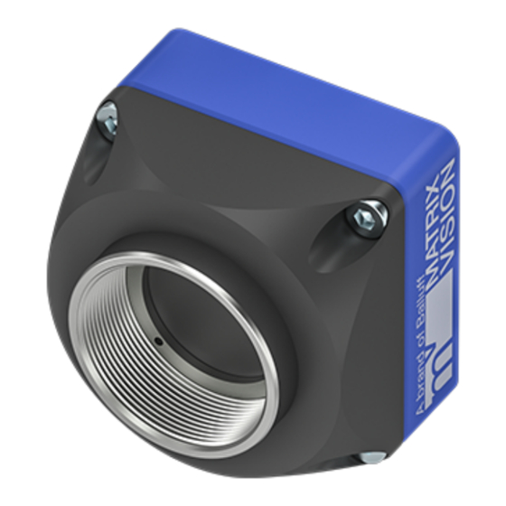
1.7 Introduction Figure 1: mvBlueNAOS The mvBlueNAOS is a PCI Express board-level camera family compliant to the GenICam GenTL Producer (p. 113) standard. The camera family combines the Sony IMX sensor with up to 16 LVDS lanes with a 4 lane PCI Express interface including Generation 2 performance. - Page 25 1.7 Introduction Figure 2: Software concept As shown in figure 2, for the mvBlueNAOS the mvIMPACT_Acquire (p. 119) interface is stacked on the Genicam (p. 113) layers. The mvIMPACT_Acquire (p. 119) interface internally uses the GenICam (p. 113) runtime libraries, so that it can be considered as a user application written with the GenICam (p.
-
Page 26: Order Code Nomenclature
1.7.2 Order code nomenclature 1.7.2.1 mvBlueNAOS2 The mvBlueNAOS2 nomenclature scheme is as follows: Sensor Model name 1.6 Mpix, 1456 x 1088, 1/2.9'', IMX273, CMOS BVS CA-BN2-0016ZG/C 3.2 Mpix, 2064 x 1544, 1/1.8'', IMX252, CMOS BVS CA-BN2-0032ZG/C 5.1 Mpix, 2464 x 2056, 2/3'', IMX250, CMOS BVS CA-BN2-0051ZG/C 8.9 Mpix, 4112 x 2176 (G) 4096 x 2176 (C), 1'', IMX255, CMOS BVS CA-BN2-0089ZG/C... -
Page 27: Mvbluenaos4
1.7 Introduction 1.7.2.2 mvBlueNAOS4 The mvBlueNAOS4 nomenclature scheme is as follows: Sensor Model name 5.1 Mpix, 2464 x 2064, 1/1.8'', IMX537, CMOS BVS CA-BN4-0051BG/C 8.1 Mpix, 2848 x 2848, 2/3'', IMX536, CMOS BVS CA-BN4-0081ZG/C 12.4 Mpix, 4128 x 3008, 1/1.1'', IMX535, CMOS BVS CA-BN4-0124BG/C 16.2 Mpix, 5328 x 3040, 1.1'', IMX532, CMOS BVS CA-BN4-0162ZG/C... -
Page 28: What's Inside And Accessories
1.7.3 What's inside and accessories Due to the varying fields of application the mvBlueNAOS is shipped without accessories. The package contents: • mvBlueNAOS For the first use of the mvBlueNAOS we recommend the following accessories to get the camera up and running: •... -
Page 29: Quickstart
1.8 Quickstart 1.8 Quickstart • System Requirements (p. 21) • Installing The mvGenTL-Acquire Package (p. 22) • Connecting The Camera (p. 30) • Driver concept (p. 33) • Relationship Between Driver, Firmware And SDK (p. 35) 1.8.1 System Requirements 1.8.1.1 Host System The mvBlueNAOS is a high-performance camera which requires a high data throughput on the host system, for example, when processing large amount of image data and high CPU resources if processing color images on the host PC. -
Page 30: Installing The Mvgentl-Acquire Package
1.8.1.2.2 Linux This following description is only valid for 64-bit ARM and Intel architectures. Please check the the 'Support' section of the MATRIX VISION website for the availability of the latest Linux driver package. See also https://matrix-vision.com/software-drivers-en.html Currently supported Kernel versions are: •... -
Page 31: Windows
1.8 Quickstart Figure 1: Connecting the rigid-flex extension cable • Select a free PCIe slot (preferably the x16 graphic card slot). Remove the slot's cover at the back of the computer and keep the screw. • Carefully insert the PCIe adapter card into the slot by holding the board at the top and gently pushing both ends into the slot at the same time. - Page 32 Figure 2: Driver installation - Start Window • Now, follow the instructions of installation program and adjust the settings to your needs: Figure 3: Driver installation - Select Installation Folder Since mvIMPACT Acquire 2.25.0 wxPropView (p. 65) is able to check if new driver version became available on a weekly basis. Deactivate the check box if wxPropView should not check for updates.
- Page 33 1.8 Quickstart Figure 4: Driver installation - Select Features • After confirmation, the installation will start and copy files and install device drivers. Figure 5: Driver installation - Installation Completed You will find all tools like • wxPropView (p. 65) and •...
- Page 34 Note You can ignore the other tools mvIPConfigure and mvGigEConfigure, because they are only necessary in combination with GigE Vision™ devices like the mvBlueCOUGAR-X. Afterwards, you can use mvDeviceConfigure (p. 65) to update the firmware if needed. The current firmware version can be read out using wxPropView (p.
-
Page 35: Linux
1.8 Quickstart 1.8.2.3 Linux The following (additional) packages will be needed to use all features of mvIMPACT Acquire: • libwxbase3.0-0v5 • libwxbase3.0-dev • libwxgtk3.0-gtk3-0v5 • libwxgtk3.0-gtk3-dev • libwxgtk-webview3.0-gtk3-0v5 • libwxgtk-webview3.0-gtk3-dev • wx3.0-headers • build-essential (meta package) • libgtk2.0-dev • gcc 4.8.5 (4.9.4 for ARM versions) environment or newer Note The names of the packages as mentioned above are the Ubuntu specific ones. - Page 36 Note If root permissions are needed, the script will ask for the permissions. There is no need to call it with root permissions. • You might need to enable the execute flag with: chmod a+x install_mvGenTL_Acquire.sh • Run the install script: ./install_mvGenTL_Acquire.sh During installation the script will ask, if it should build all tools and samples.
- Page 37 SecureBoot requires the Linux kernel and all loadable kernel modules to be signed using a digital signature saved on the system. Since the MATRIX VISION mvBlueNAOS PCIe camera makes use of a kernel module which has been individually built for the system, this kernel module must also be signed in order to be loadable.
-
Page 38: Connecting The Camera
1.8.3 Connecting The Camera To start the device please accomplish following steps: 1. Power down the host system 2. Connect the mvBlueNAOS to the host system using the appropriate adapter • PCIe or M.2 Key M and • cable 3. Power up the host system. The mvBlueNAOS will boot immediately. - Page 39 1.8 Quickstart • For the GenICam interface layout all device properties modified during a continuous acquisition will be applied at once so might affect this or the next image transmitted by the device. Depending on various parameters (the number of buffer already captured but not collected by the application, the way the device internally operates(e.g.
- Page 40 • On Windows the driver will not look for a matching XML file during start-up automatically as the native storage location for settings is the Windows Registry. This must be loaded explicitly by the user by using the appropriate API function offered by the SDK. However, under Linux XML files are the only setting formats understood by the driver framework thus here the driver will also look for them at start-up.
-
Page 41: Driver Concept
1.8 Quickstart 1.8.4 Driver concept The driver supplied with the MATRIX VISION product represents the port between the programmer and the hardware. The driver concept of MATRIX VISION provides a standardized programming interface to all image processing products made by MATRIX VISION GmbH. The advantage of this concept for the programmer is that a developed application runs without the need for any major modifications to the various image processing products made by MATRIX VISION GmbH. -
Page 42: Visionpro Support
• 4 Part of the NeuroCheck installer but requires at least one installed frame grabber driver. • 5 Part of the mvIMPACT SDK installation. However, new designs should use the .NET libs that are now part of mvIMPACT Acquire ( "mv.impact.acquire.dll"... -
Page 43: Relationship Between Driver, Firmware And Sdk
1.8 Quickstart 1.8.5 Relationship Between Driver, Firmware And SDK In order to operate an mvBlueNAOS, not only the hardware but also the corresponding software is required. This can be installed via the mvIMPACT Acquire GenTL-Acquire package and consists of the following different parts. 1. -
Page 44: Technical Data
1.9 Technical Data 1.9.1 mvBlueNAOS2 1.9.1.1 Dimensions 1.9.1.1.1 BVS CA-BN2-xxxxx-x5x110 (Standard housing with NAOS for Embedded (N4e) interface) Figure 1: Connectors BVS CA-BN2-xxxxx-x5x110 mvBlueNAOS2 Size of body (w x h x l) 40 x 40 x 27 mm MATRIX VISION GmbH... - Page 45 1.9 Technical Data 1.9.1.1.2 BVS CA-BN2-xxxxx-x00010 (Board-level) Figure 2: Connectors BVS CA-BN2-xxxxx-x00010 mvBlueNAOS Size of body (w x h x l) 37 x 37 x 6.9 mm MATRIX VISION GmbH...
-
Page 46: Mvbluenaos4
1.9.2 mvBlueNAOS4 1.9.2.1 Dimensions 1.9.2.1.1 BVS CA-BN4-xxxxx-x5x510 (Board-level) Figure 3: Connectors BVS CA-BN4-xxxxx-x5x510 mvBlueNAOS4 Size of body (w x h x l) 55 x 40 x 26.5 mm MATRIX VISION GmbH... -
Page 47: Naos For Embedded (N4E) Interface
1.9 Technical Data 1.9.3 NAOS for Embedded (N4e) Interface The NAOS for Embedded (N4e) interface provides PCIe Gen.2 and various I/O functionality on a single 70-pin Board-to-Board connector. The main features of the user I/O interface are • 4 digital inputs, •... -
Page 48: Pin Assignment
1.9.3.1 Pin assignment Note The red dot marks pin 1 of Hirose DF40GB(3.0)-70DS-0.4V. Signal Description VCC_IN Input Voltage (5V-12V) VCC3V3 Power Output, max. 10mA for customer use VCC_IN Input Voltage (5V-12V) I2C_SCL_USER I2C_USER (see details below) LVCMOS 3.3V IO level VCC_IN Input Voltage (5V-12V) I2C_SDA_USER... - Page 49 1.9 Technical Data Ground PCIe_RX0_N PCIe Receiver (differential) PCIe_PERST Reset Ground Ground Ground Ground Ground PCIe_TX2_P PCIe Transmitter (differential) PCIe_RX2_P PCIe Receiver (differential) PCIe_TX2_N PCIe Transmitter (differential) PCIe_RX2_N PCIe Receiver (differential) Ground Ground PCIe_TX3_P PCIe Transmitter (differential) PCIe_RX1_P PCIe Receiver (differential) PCIe_TX3_N PCIe Transmitter (differential) PCIe_RX1_N...
- Page 50 1.9.3.1.1 Electrical characteristics of signals Input Voltage Parameter Description Unit VCC_IN VCC_IN I per pin VCC_IO / DIGIN / DIGOUT Parameter Description Unit VCC_IO I/O voltage power Low-level input voltage DIG_IN_LOW High-level input voltage 0.7 x VCC_IO DIG_IN_HIGH Output current for VCC_IO = 3.3 V Output current for VCC_IO = 3.3 V Output voltage for VCC_IO = 3.3 V, I = -24 mA...
-
Page 51: Add-In Cards For The Naos For Embedded (N4E) Interface
1.9 Technical Data 1.9.3.2 Add-in cards for the NAOS for Embedded (N4e) Interface BNE-IF-PCIeX4-N4e-IO14 Add-in card for connecting the camera to the PCIe x4 slot of a host board. The board includes • the N4e interface (CON2) • a 14-pin I/O connector (CON3) and •... - Page 52 Pin assignments 12-pin I/O connector (CON3) Figure 7: 14-pin I/O connector (CON3 • Part type: – Wire to Bord Connector 1.25mm MOLEX PicoBlade 53048_1410 • Connecting part: – Molex 0510211400, 1.25 Wire to Board Connection Receptacle Crimp Housing, Applicable Terminal 50058-8000, 50079-8000 Series Signal Description...
- Page 53 1.9 Technical Data Note Optional user defined VCC_IO voltage 1.8 V .. 5.5 V possible. For further information please contact MATRIX VISION. "Serial interface RS232" Parameter Description Unit EIA/TIA-232E Input Voltage Range EIA/TIA-232E Input Threshold Low EIA/TIA-232E Input Threshold High EIA/TIA-232E Input Hysteresis EIA/TIA-232E Input Resistance Output Voltage Swing...
-
Page 54: Oculink
1.9.4 OCuLink The OCuLink interface provides PCIe Gen.2 functionality on a single 42-pin connector. Figure 8: OCuLink interface "Camera connector" • Amphenol type G14A42211912HRV "Matching cable" Used for accessory IO Boards or customer implementation. • OCuLink standard cable, for example Molex 2060611151/2021431003 or similar from other suppliers MATRIX VISION GmbH... -
Page 55: Pin Assignment
1.9 Technical Data 1.9.4.1 Pin assignment Note The red dot marks pin 1. Signal Description Do not connect Ground PCIe_RX0_P PCIe Receiver IN (differential) PCIe_RX0_N PCIe Receiver IN (differential) Ground PCIe_RX1_P PCIe Receiver IN (differential) PCIe_RX1_N PCIe Receiver IN (differential) Ground Do not connect WAKE_PCIE... -
Page 56: Power/Io Connector (For Oculink Model)
1.9.4.1.1 Electrical characteristics of signals Input Voltage Signal Unit V_IN VCC_IN I per pin Power Down Signal Properties Unit Voltage level PCIe_PERST_N (low level input voltage) (high level input voltage) Voltage level (low level input voltage) WAKE_PCIe (high level input voltage) Current WAKE_PCIe 1.9.4.2 Power/IO connector (for OCuLink model) Figure 9: Power/IO connector (for OCuLink model) - Page 57 1.9 Technical Data Signal Description GND (for PWR_IN) Ground for Power-In PWR_IN (p. 52) Power-In Opto DigIn_GND Ground for opto-coupler (In) DigOut_PWR_IN Power-In for the opto-coupler outputs Opto DigIn0 Digital input, opto-coupler Opto DigOut0 Digital output, opto-coupler Opto DigIn1 Digital input, opto-coupler Opto DigOut1 Digital output, opto-coupler DigOut2...
- Page 58 Characteristics of input voltage Characteristics min. nom. max. Unit Camera power supply Camera current supply Characteristics of the digital inputs Figure 10: DigIn Opto DigIn Characteristics min. nom. max. Unit (low level input voltage) Opto DigIn_LOW (high level input voltage) Opto DigIn_HIGH Switching Frequency Characteristics of the digital outputs...
-
Page 59: Signal Led
1.9 Technical Data Opto DigOut Characteristics min. nom. max. Unit (low level input voltage) Opto DIG_OUT_LOW (high level input voltage) Opto DIG_OUT_HIGH at I = 7 mA CE(sat) Load current Switching characteristics Characteristics Test Conditions Typ. Unit Turn-On time Storage time = 100 Ohm, V 10 V, I = 2 mA... - Page 60 Features mvBlueNAOS2 mvBlueNAOS4 Image Memory Flash (FPGA Configuration, Device Specific Data) 16 MByte PCIe Interface x4 Gen2 PCIe Bandwidth max. 16 Gbit/s Max. effective PCIe Bandwidth 12.8 Gbit/s Bandwidth FPGA Pipeline 800 MPixel/s 1300 MPixel/s SLVS Lanes SLVS-EC Lanes Inputs Outputs RS232 Controlling e.g.
-
Page 61: Summary Of Advanced Features
1.9 Technical Data 1.9.7 Summary of advanced features The following table shows an excerpt of the advanced features. Advanced features mvBlueNAOS2 mvBlueNAOS4 MultiFrame / SingleFrame / Continuous (p. 69) Auto Exposure Control (AEC) (p. 69) Auto Gain Control (AGC) (p. 69) Auto white balance (AWB) Binning / Decimation (p. -
Page 62: Sensor Overview
1.10 Sensor Overview 1.10.1 Image data flow The following block diagrams show the data flow of the image data after being read from the sensor chip in the camera. The transfer latency (stream controller + resend buffer + packet generator) of the data is less than 100 us. Figure 1: Block diagram Measured accord. -
Page 63: Debayering Of Color Sensors (Rgb Bayer)
1.10 Sensor Overview 1.10.3 Debayering of color sensors (RGB Bayer) For Bayer demosaicing in the camera, we use our "Adaptive Edge Sensing Plus" method. I.e. "Adaptive Edge Sensing Plus" detects edges, filters and sharpens them depending on the location. It tries to reconstruct the green channel based on a gradient. -
Page 64: Supported Image Formats
1.10.4 Supported image formats It depends on the sensor model which image formats are actually supported. The parameter PixelFormat in the ImageFormatControl (p. 68) lists all the supported image formats of the specific camera model. In wxPropView (p. 65) you can find the PixelFormat parameter in "Setting - Base - Camera - GenICam -... -
Page 65: Cmos Sensors
1.10 Sensor Overview 1.10.5 CMOS sensors Approximately 33 % of power is consumed by the sensor board and the rest by the main board. The main consumers are the FPGA and the sensor itself. Approximately 15 % of consumption is spread over various voltage regulators. Summary of CMOS sensors (p. - Page 66 IMX252 Gray 2064 1/1. 191. 40,2 71,3 Global X / X 3.45 (Sony) 1544 BN2- 0032 (3.2 Mpix [2064 1544]) (p. 215) IMX253 Color 4096 40,2 70,9 Global X / X 3.45 (Sony) 3008 BN2- 0124 (12. Mpix [4096 3008]) (p.
- Page 67 1.10 Sensor Overview IMX255 Gray 4112 40,3 71,0 Global X / X 3.45 (Sony) 2176 BN2- 0089 (8.9 Mpix [4112 2176]) (p. 220) IMX273 Color 1456 1/2. 226. 40,2 71,4 Global X / X 3.45 (Sony) 1088 BN2- 0016 (1.6 Mpix [1456 1088])
- Page 68 IMX530 Gray 5328 39,8 70,3 Global X / X 2.74 - - - (Sony) 4608 BN4- 0246 (24. Mpix [5328 4608]) (p. 240) IMX531 Color 4512 Global X / X 2.74 - - - (Sony) 4512 BN4- 0204 (20. Mpix [4512 4512]) (p.
- Page 69 1.10 Sensor Overview IMX532 Gray 5328 39,8 71,7 Global X / X 2.74 - - - (Sony) 3040 BN4- 0162 (16. Mpix [5328 3040]) (p. 235) IMX535 Color 4128 1/1. 104. 39,6 69,5 Global X / X 2.74 - - - (Sony) 3008 BN4-...
- Page 70 IMX536 Gray 2848 152. 39,7 69,6 Global X / X 2.74 - - - (Sony) 2848 BN4- 0081 (8.1 Mpix [2848 2848]) (p. 230) IMX537 Color 2464 1/1. 234. 39,8 69,6 Global X / X 2.74 - - - (Sony) 2064 BN4- 0051...
-
Page 71: Filters
1.11 Filters IMX540 Gray 5328 39,6 70,2 Global X / X 2.74 (Sony) 4608 BN2- 0246 (24. Mpix [5328 4608]) (p. 225) 1.11 Filters MATRIX VISION offers several specific filters for cameras. The hot mirror filter (p. 63) is part of the standard delivery condition. -
Page 72: Cold Mirror Filter
1.11.2 Cold mirror filter The high-quality daylight cut filter has optically polished surfaces. The polished surface allows the use of the filter directly in the path of rays in image processing applications. The filter is protected against scratches during the transport by a protection film that has to be removed before the installing the filter. -
Page 73: Gui Tools
1.12 GUI tools 1.12 GUI tools 1.12.1 Introduction MATRIX VISION provides several convenient tools with graphical user interface to set up and work with their devices. Please find a short list and description below: 1.12.2 wxPropView With wxPropView it is possible •... -
Page 74: Genicam And Advanced Features
1.13 GenICam and advanced features 1.13.1 Introduction In wxPropView (p. 65), you can see them in "Setting - Base - Camera - GenICam": Figure 1: wxPropView - GenICam controls (depends on device and FW version) As you can see, there are some controls with and without the prefix "mv". •... - Page 75 1.13 GenICam and advanced features Feature name (acc. to SFNC Property name (acc. to mvIMPACT Description (p. 121)) Acquire (p. 119)) DeviceType deviceType Returns the device type. DeviceScanType deviceScanType Scan type of the sensor of the de- vice. DeviceVendorName deviceVendorName Name of the manufacturer of the device.
-
Page 76: Image Format Control
1.13.3 Image Format Control The "Image Format Control" contains features like Feature name (acc. to SFNC Property name (acc. to mvIMPACT Description (p. 121)) Acquire (p. 119)) SensorWidth sensorWidth Effective width of the sensor in pix- els. SensorHeight sensorHeight Effective height of the sensor in pix- els. -
Page 77: Acquisition Control
1.13 GenICam and advanced features 1.13.4 Acquisition Control The "Acquisition Control" contains features like to SFNC Property name (acc. to mvIMPACT Feature name (acc. Description (p. 121)) Acquire (p. 119)) AcquisitionMode acquisitionMode Sets the acquisition mode of the device. The different modes con- figures a device to send •... - Page 78 acquisitionFrameRate Controls the acquisition rate (in AcquisitionFrameRate Hertz) at which the frames are cap- tured. Some cameras support a special internal trigger mode that allows more exact frame rates. This fea- ture keeps the frame rate constant to an accuracy of +/-0.005 fps at 200 fps.
- Page 79 1.13 GenICam and advanced features related to the image acquisition, including the triggering mode. Additionally, MATRIX VISION offers numerous additional features like: • mvShutterMode which selects the shutter mode of the CMOS sensors like rolling shutter or global shutter. • mvDefectivePixelEnable which activates the sensor's defective pixel correction.
- Page 80 • mvSmartFrameRecallFrameSkipRatio When set to a value != 0, the smaller frames get thinned out. AOI requests can still be done for all frames. • mvSmartFrameRecallTimestampLookupAccuracy is needed for the SkipRatio feature since you don't know the timestamps of the internal frames. This value defines the strictness of the timestamp-check for the recalled image (given in us).
-
Page 81: Counter And Timer Control
1.13 GenICam and advanced features 1.13.5 Counter And Timer Control The "Counter And Timer Control" is a powerful feature which MATRIX VISION customers already know under the name Hardware Real-Time Controller (HRTC). MATRIX VISION cameras provide: • 4 counters for counting events or external signals (compare number of triggers vs. number of frames; over- trigger) and •... - Page 82 • Outputting a pulse at every other external trigger (p. 164) • Generating very long exposure times (p. 124) MATRIX VISION GmbH...
-
Page 83: Analog Control
1.13 GenICam and advanced features 1.13.6 Analog Control The "Analog Control" contains features like Feature name (acc. to SFNC Property name (acc. to mvIMPACT Description (p. 121)) Acquire (p. 119)) GainSelector gainSelector Selects which gain is controlled by the various gain features. Gain[GainSelector] gain Controls the selected gain as an... - Page 84 Figure 3: Analog Control - Gain Auto See also Optimizing the color/luminance fidelity of the camera (p. 138) MATRIX VISION GmbH...
-
Page 85: Color Transformation Control
1.13 GenICam and advanced features 1.13.7 Color Transformation Control The "Color Transformation Control" contains features like Feature name (acc. to SFNC Property name (acc. to mvIMPACT Description Acquire (p. 119)) (p. 121)) ColorTransformationSelector colorTransformationEnable Activates the selected color trans- formation module. ColorTransformationSelector colorTransformationSelector Selects which color transformation... -
Page 86: Event Control
1.13.8 Event Control The "Event Control" contains features like Feature name (acc. to SFNC Property name (acc. to mvIMPACT Description Acquire (p. 119)) (p. 121)) EventSelector eventSelector Selects which Event to signal to the host application. EventNotification[EventSelector] eventNotification Activate or deactivate the notifica- tion to the host application of the occurrence of the selected Event. -
Page 87: Chunk Data Control
1.13 GenICam and advanced features 1.13.9 Chunk Data Control The "Chunk Data Control" contains features like Feature name (acc. to SFNC Property name (acc. to mvIMPACT Description Acquire (p. 119)) (p. 121)) ChunkModeActive chunkModeActive Activates the inclusion of chunk data in the payload of the image. ChunkSelector chunkSelector Selects which chunk to enable or... -
Page 88: File Access Control
1.13.10 File Access Control The "File Access Control" contains features like Feature name (acc. to SFNC Property name (acc. to mvIMPACT Description Acquire (p. 119)) (p. 121)) FileSelector fileSelector Selects the target file in the device. FileOperationSelector[File fileOperationSelector Selects the target operation for the Selector] selected file in the device. -
Page 89: Transport Layer Control
1.13 GenICam and advanced features 1.13.12 Transport Layer Control The "Transport Layer Control" contains features like to SFNC Property name (acc. to mvIMPACT Feature name (acc. Description (p. 121)) Acquire (p. 119)) PayloadSize payloadSize Provides the number of bytes trans- ferred for each image or chunk on the stream channel. -
Page 90: User Set Control
1.13.13 User Set Control The "User Set Control" contains features like Feature name (acc. to SFNC Property name (acc. to mvIMPACT Description Acquire (p. 119)) (p. 121)) UserSetSelector userSetSelector Selects the feature user set to load, save or configure. UserSetLoad[UserSetSelector] userSetLoad Loads the user set specified by UserSetSelector to the device and... -
Page 91: Mv Logic Gate Control
1.13 GenICam and advanced features 1.13.14 mv Logic Gate Control The "mv Logic Gate Control" contains features like Feature name (acc. to SFNC Property name (acc. to mvIMPACT Description (p. 121)) Acquire (p. 119)) mvLogicGateANDSelector Selects the AND gate to configure. mvLogicGateANDSource1 Selects the first input signal of the AND gate selected by mvLogic... -
Page 92: Mv Serial Interface Control
1.13.15 mv Serial Interface Control The "mv Serial Interface Control" contains features like Feature name (acc. to SFNC Property name (acc. to mvIMPACT Description Acquire (p. 119)) (p. 121)) mvSerialInterfaceMode States the interface mode of the se- rial interface. mvSerialInterfaceEnable Controls whether the serial inter- face is enabled or not. - Page 93 1.13 GenICam and advanced features related to the automatic control of exposure, gain, and white balance. With this control you can influence the characteristic of the controller depending on certain light situations. AEC/AGC can be controlled with the new additional properties mvAutoFeatureSensitivity, mvAutoFeatureCharacteristic and mvAutoFeatureBrightnessTolerance.
-
Page 94: Developing Applications Using The Mvimpact Acquire Sdk
1.14 Developing applications using the mvIMPACT Acquire SDK mvIMPACT Acquire SDK is a comprehensive software library that can be used to develop applications using the devices described in this manual. A wide variety of programming languages is supported. For C, C++, .NET, Python or Java developers separate API descriptions can be found on the MATRIX VISION website: •... -
Page 95: Directshow Interface
1.15 DirectShow interface 1.15 DirectShow interface Note DirectShow can only be used in combination with the Microsoft Windows operating system. Since Windows Vista, Movie Maker does not support capturing from a device registered for DirectShow anymore. This is the documentation of the MATRIX VISION DirectShow_acquire interface. A MATRIX VISION specific prop- erty interface based on the IKsPropertySet has been added. -
Page 96: Registering Devices
Note Please be sure to register the MV device for DirectShow with a matching version of mvDeviceConfigure. I.e. if you have installed the 32-bit version of the VLC Media Player, Virtual Dub, etc., you have to register devices with the 32-bit version of mvDeviceConfigure ("C:\Program Files\MATRIX VISION\mv IMPACT Acquire\bin", the 64-bit version resides in "C:\Program Files\MATRIX VISION\mvIMPACT Ac- quire\bin\x64")! 1.15.3.1 Registering devices... - Page 97 1.15 DirectShow interface mvDeviceConfigure - Register All Devices 3. After a successful registration the column "Registered For DirectShow" will display "yes" for every device and the devices will be registered with a default DirectShow friendly name which is displayed in the "DirectShow Friendly Name"...
-
Page 98: Renaming Devices
1.15.3.2 Renaming devices To modify the DirectShow friendly name of a device: 1. mvDeviceConfigure needs to be started(with elevated rights). 2. right-click on the device to rename and select "Set DirectShow Friendly Name": mvDeviceConfigure - Set DirectShow Friendly Name 3. Then, a dialog will appear. Please enter the new name and confirm it with "OK". mvDeviceConfigure - Dialog For New Name 4. -
Page 99: Using Regsvr32
1.15 DirectShow interface mvDeviceConfigure - Renamed Device Note Please do not select the same friendly name for two different devices. In theory this is possible, however the mvDeviceConfigure GUI will not allow this to avoid confusion. 1.15.3.3 Using regsvr32 To register all devices currently recognized by the mvIMPACT Acquire driver stack with auto-assigned names, the Windows tool "regsvr32"... -
Page 100: Troubleshooting
1.16 Troubleshooting • Error code list (p. 92) • Accessing log files (p. 105) • General Issues (p. 106) • Windows (p. 110) Windows • Linux (p. 111) 1.16.1 Error code list Numerical Value String Representation Brief Description Detailed Description -2000 PROPHANDLING_NOT_ This component is not a list. - Page 101 1.16 Troubleshooting -2005 PROPHANDLING_NO_ The caller can't modify the It has been tried to mod- MODIFY_SIZE_RIGHTS size of this component. ify the size of this list or the number of values stored by a property, but the caller doesn't have the required right to do this.
- Page 102 -2012 PROPHANDLING_ It has been tried to assign an This can either happen if the INVALID_PROP_VALUE invalid value to a property. value lies above or below the min. or max. value for a property or when it has been tried to write a value to a property, which is not in the properties translation dictionary (if it defines one).
- Page 103 1.16 Troubleshooting -2016 PROPHANDLING_ An invalid value has been Although properties INVALID_PROP_VALUE_ passed to the property. quite tolerant regarding the TYPE allowed assignment for them some value types can't be used to write all properties. As an example assigning a float value to an integer property would result in this error.
- Page 104 -2025 PROPHANDLING_LIST_ The desired data can't be During loading or saving CANT_ACCESS_DATA accessed or found. data this error can occur e.g. if it has been tried to import a setting from a location where the desired setting couldn't be found. Another reason for this error might be that the current user is not allowed to perform a certain opera-...
- Page 105 1.16 Troubleshooting -2034 PROPHANDLING_CANT user tried [-2034] _SERIALIZE_DATA save(serialize) prop- erty list without having the right to do this. -2035 PROPHANDLING_ The user tried to use a file This e.g. might happen, if INVALID_FILE_CONTENT to update or create a compo- the file does not contain valid nent list, that does not con- XML data or XML data that is...
- Page 106 -2103 DMR_DEV_CANNOT_ The specified device couldn't [-2103] OPEN be initialized. -2104 DMR_NOT_INITIALIZED The device manager or an- This error occurs if the user other module hasn't been tries e.g. to close the de- initialized properly. vice manager without hav- ing initialized it before or if a library used internally or a module or device associated with that library has not been...
- Page 107 1.16 Troubleshooting -2109 DMR_EXPORTED_ more symbols In most cases this is an er- SYMBOL_NOT_FOUND needed in a detected driver ror handled internally. So the library couldn't be resolved. user will not receive this er- ror code as a result of a call to an API function.
- Page 108 -2115 DEV_REQUEST_CANT_ The unlock for a Request ob- This might happen, if the Re- BE_UNLOCKED ject failed. quest is not locked at the time of calling the unlock function. It either has been unlocked by the user already or this request has never been locked as the request so far has not been used to capture image data into its...
- Page 109 1.16 Troubleshooting -2121 DEV_INVALID_RTC_ The requested real time con- [-2121] NUMBER troller is not available for this device. -2122 DMR_INTERNAL_ERROR Some kind of internal error More information can be occurred. found in the .log-file or the debug output. [-2122] -2123 DMR_INPUT_BUFFER_ The user allocated input [-2123]...
- Page 110 -2132 DMR_CAMERA_ A function call was associ- One possible reason might DESCRIPTION_INVALID ated with a camera descrip- be, that the camera descrip- tion, that is invalid. tion has been deleted(driver closed?). 1.5.0 [-2132] -2133 DMR_NEWER_LIBRARY A suitable driver library to This might happen if two dif- _REQUIRED work with the device man-...
- Page 111 1.16 Troubleshooting -2137 DEV_REQUEST_ This request is currently This error may occur if the ALREADY_IN_USE used by the driver. user tries to send a certain request object to the driver by a call to the correspond- ing image request function. 1.10.31 [-2137] -2138...
- Page 112 -2141 DMR_PRELOAD_ A pre-load condition for load- Certain device drivers may CHECK_FAILED ing a device driver failed. depend on certain changes applied to the system in or- der to operate correctly. E.g. a device driver might need a certain environment variable to exist.
-
Page 113: Accessing Log Files
1.16 Troubleshooting -2145 DMR_ACQUISITION_ An error returned when the 2.5.3 ENGINE_BUSY user application attempts to [-2145] start the acquisition engine at a time, where it is already running. -2146 DMR_BUSY An error returned when the The log-output will provide user application attempts to additional information. -
Page 114: General Issues
For older versions: Like on Windows, log files will be generated, if the activation flag for logging called mvDebugFlags.mvd is avail- able in the same folder as the application (however, using Windows log files will be generated automatically, be- cause the applications are started from the same folder). By default, on Linux the mvDebugFlags.mvd will be installed in the installation's destination folder in the sub-folder . -
Page 115: The Error Counter Increases
1.16 Troubleshooting 1.16.3.1 The error counter increases Modern PC's, notebook's, etc. try to save energy by using a smart power management. If processor performance is not needed the processor will change to a power saving (sleep) state automatically and vice versa. Every state change will stop the processor for microseconds. -
Page 116: Which Pc Power Settings Are Useful And Possibly Necessary
Swiching off Intel SpeedShift options might improve the situation Swiching off Intel SpeedStep options might improve the situation Note Another that is always worth considering is to look for an updated version of your systems BIOS! When- ever you encounter problems like described above and you are sure that you have set up the system as perfect as possible (e.g. -
Page 117: Why Does Updating The Device List Take So Long
1.16 Troubleshooting Component Recommendation C-States EIST Disabled ASPM Disabled Windows Component Recommendation High Perfomance power plan Selected PCI Express Link State Power Management (Advanced power settings) Alternatively: Component Recommendation Ultimate Perfomance power plan Selected See also https://www.howtogeek.com/368781/how-to-enable-ultimate-performance-power-plan-in-w Linux Boot the Linux kernel with the parameter: Component Recommendation pcie_aspm... -
Page 118: Windows
Figure 1: "Missing A Device? Click here..." Now, you will see the interfaces and the detected device. 4. Finally, you can deselect the interfaces or devices which you do not want to scan for updating the device list. The following figure shows that the GigE Vision interface should be skipped: Figure 2: Skip the GigE Vision interface 1.16.4 Windows •... -
Page 119: Linux
1.16 Troubleshooting 1.16.4.1 Bluescreen On Machines Running Windows 10 Or Higher When Streaming Is Started Symptoms On systems running Windows 10 or higher a Bluescreen "DRIVER-VERIFIER-DMA-VIOLATION" shows up when the streaming is started. Cause The root cause is that on newer systems a protection mechanism is used which prevents PCIe devices accessing DMA memory per default. -
Page 120: No Genicam Devices Are Detected On A Linux System
1.16.5.1 No GenICam devices are detected on a Linux system Symptoms After starting any mvIMPACT Acquire based application no GenICam compliant devices are accessible or detected Cause The environment variables which are necessary to us the mvGenTL Acquire package are defined by two shell scripts which are set by profile.d. -
Page 121: Glossary
1.17 Glossary 1.17 Glossary Analog-to-digital converter (A/D converter). Application programming interface (API). The standard API for MATRIX VISION products is called mvIMPACT_Acquire (p. 119). Configurable monolithic application including shell and other useful BusyBox command line tools - often called the "swiss army knife" for embedded systems. - Page 122 The term Gigabit Ethernet (defined by the Gigabit Ethernet (GigE) IEEE 802.3-2008 standard) represents various technologies for transmitting Ethernet frames at a rate of a gigabit per second (1,000,000,000 bits per second). MATRIX VISION GmbH...
- Page 123 1.17 Glossary GigE Vision is a network protocol designed for the GigE Vision communication between an imaging device and an application. This proto- col completely describes: • device discovery • data transmission – image data – additional data • read/write of parameters. GigE Vision uses UDP for data transmission to reduce overhead in- troduced by TCP.
- Page 124 High Dynamic Range (HDR) The HDR (High Dynamic Range) mode increases the usable contrast range. This is achieved by dividing the integration time in two or three phases. The exposure time proportion of the three phases can be set independently. Furthermore, it can be set, how many signal of each phase is charged.
- Page 125 1.17 Glossary Logical link address (LLA) is a type of mechanism to obtain a valid IP address without a DHCP server being present. Whether an IP address is available or not is resolved using address resolution protocol (ARP) packets. If no ARP response is received on a given address it is considered unused and will be assigned to the interface.
- Page 126 In the tab "IPv4 Setting" you have to set "Link-Local Only": After saving, you will find both connections in the summary: Now, you can select the wished connection using the left mouse button in the "Network Manager" menu. In the LLA case it is just the new created connection: Media Access Control address (MAC address) is MAC address...
- Page 127 1.17 Glossary Maximum transmission unit (MTU) refers to the size (in bytes) of the largest packet that a given layer of a communications protocol can pass onwards. The default MTU for Ethernet is 1500. The optimum for Gigabit Ethernet is 8000 - 12000. Different MTU settings in the same subnet can cause package losses, i.e.
- Page 128 By default, the steps exposure and readout out of an image sensor are Overlapped / pipelined transfer done one after the other. • By design, CCD sensors support overlap capabilities also combined with trigger (see figure). • In contrast, so-called pipelined CMOS sensors only support the over- lapped mode.
- Page 129 1.17 Glossary Standard Feature Naming Convention SFNC of GenICam (p. 113). See also latest GenICam properties list found here: http://www.emva. org/standards-technology/genicam/genicam-downloads/ The file is called "GenICam Standard Features Naming Convention (PDF)" In computing, a shell is a piece of software that provides an Shell interface for users.
-
Page 130: Use Cases
1.18 Use Cases • Introducing acquisition / recording possibilities (p. 123) • Improving the acquisition / image quality (p. 133) • Working with triggers (p. 160) • Working with I/Os (p. 177) • Saving data on the device (p. 184) •... -
Page 131: Introducing Acquisition / Recording Possibilities
1.18 Use Cases 1.18.1 Introducing acquisition / recording possibilities There are several use cases concerning the acquisition / recording possibilities of the camera: • Acquiring a number of images (p. 123) • Generating very long exposure times (p. 124) • Working with multiple AOIs (mv Multi Area Mode) (p. 126) •... -
Page 132: Generating Very Long Exposure Times
Figure 2: wxPropView - Setting acquisition of a number of images started by an external signal A rising edge at line 4 will start the acquisition of 20 images. 1.18.1.2 Generating very long exposure times 1.18.1.2.1 Basics At the moment the exposure time is limited to a maximum of 1 up to 20 seconds depending on certain internal sensor register restrictions. - Page 133 1.18 Use Cases 2. set "Timer Trigger Source" = "UserOutput0". 3. set "Timer Trigger Activation" = "RisingEdge". I.e. a rising edge on UserOutput0 will start Timer1. 4. Then set the "Timer Duration" property to the desired exposure time in us. 5.
-
Page 134: Working With Multiple Aois (Mv Multi Area Mode)
ctc.timerTriggerSource.writeS("UserOutput0"); ctc.timerTriggerActivation.writeS("RisingEdge"); // Set timer duration for Timer1 to value from user input ctc.timerDuration.write(exposureSec * 1000000); // set userOutputSelector to UserOutput0 and set UserOutput0 to inactive. // We will later generate a pulse here to initiate the exposure ioc.userOutputSelector.writeS("UserOutput0"); ioc.userOutputValue.write(TBoolean.bFalse); // establish access to the AcquisitionCotrol interface GenICam.AcquisitionControl ac = new mv.impact.acquire.GenICam.AcquisitionControl(pDev);... - Page 135 1.18 Use Cases Figure 1: Multiple AOIs principle The "Resulting Offset X" and "Resulting Offset Y" indicates the starting point of the specific AOI in the output image. To complete the rectangular output image, the "missing" areas are filled up with the image data horizontally and vertically.
- Page 136 Figure 2: wxPropView - Multiple AOIs 7. Finally, start the acquisition by clicking the button "Acquire". 1.18.1.3.2.1 Using the Multi AOI wizard Since mvIMPACT Acquire 2.19.0 wxPropView (p. 65) offers a wizard for the Multi AOI usage: Figure 3: wxPropView - Wizard menu MATRIX VISION GmbH...
- Page 137 1.18 Use Cases The wizard can be used to get a comfortable overview about the settings of the AOIs and to create and set the AOIs in a much easier way: Figure 4: wxPropView - Multi AOI wizard Just • select the desired mvArea tabs, •...
-
Page 138: Working With Event Control
1.18.1.3.3 Programming multiple AOIs #include <mvIMPACT_CPP/mvIMPACT_acquire.h> #include <mvIMPACT_CPP/mvIMPACT_acquire_GenICam.h> GenICam::ImageFormatControl ifc( pDev ); ifc.mvMultiAreaMode.writeS( "mvMultiAreasCombined" ); ifc.mvAreaSelector.writeS( "mvArea0" ); ifc.mvAreaEnable.write( bTrue ); ifc.mvAreaOffsetX.write( 0 ); ifc.mvAreaOffsetY.write( 0 ); ifc.mvAreaWidth.write( 256 ); ifc.mvAreaHeight.write( 152 ); ifc.mvAreaSelector.writeS( "mvArea1" ); ifc.mvAreaEnable.write( bFalse ); ifc.mvAreaSelector.writeS( "mvArea2" ); ifc.mvAreaEnable.write( bFalse );... - Page 139 1.18 Use Cases 3. click on "Attach Callback". Figure 1: wxPropView - "Attach Callback" to Event Exposure End Frame ID Now, you can track the property modifications in the output window: MATRIX VISION GmbH...
- Page 140 Figure 2: wxPropView - Output window with the Event notifications You can find a detailed Callback code example in the C++ API manual MATRIX VISION GmbH...
-
Page 141: Improving The Acquisition / Image Quality
1.18 Use Cases 1.18.2 Improving the acquisition / image quality There are several use cases concerning the acquisition / image quality of the camera: • Correcting image errors of a sensor (p. 133) • Optimizing the color/luminance fidelity of the camera (p. 138) •... - Page 142 1.18.2.1.2 Defect pixel detection using mvIMPACT Acquire As mentioned, the defect pixel list can be gener- ated using mvIMPACT Acquire. Since there are three types of defects, mvIMPACT Acquire offers three calibration methods for detection: 1. leaky pixel (in the dark) which indicates pixels that produce a higher read out code than the average 2.
- Page 143 1.18 Use Cases The filter checks: Pixel > T[hot] // (default value: 15 %) // T[hot] = deviation of the average gray value Pixel < T[cold] // (default value: 15 %) // T[cold] = deviation of the average gray value Note Repeating the defective pixel corrections will accumulate the correction data which leads to a higher value in...
- Page 144 The section "Setting - Base - ImageProcessing - DefectivePixelsFilter" was also extended (see Figure 2). First, "DefectivePixelsFound" indicates the number of found defective pixels. The coordinates are available through the properties "DefectivePixelOffsetX" "DefectivePixelOffsetY" now. In addition to that it is possible to edit, add and delete these values manually (via right-click on the "DefectivePixel and select "Append Value"...
- Page 145 1.18 Use Cases Figure 3: Defective pixel data are written to the camera (since driver version 2.17.1 and firmware version 2.12.406) While opening the camera, the camera will load the defective pixel data from the camera. If there are pixels in the filter available (via calibration), nevertheless you can load the values from the camera.
-
Page 146: Optimizing The Color/Luminance Fidelity Of The Camera
1.18.2.1.5 List-based defect Pixel correction on the camera As described before, it is possible to upload lists of defect pixel onto the camera. Different algorithms can be used to determine whether a pixel is defective or not, which is dependent of how much it is allowed a pixel to deviate, temperature, gain, and exposure time. As described before, the list-based correction is deterministic, meaning it is exactly known which pixels will be corrected. - Page 147 1.18 Use Cases • camera based settings and adjustments or • host based settings and adjustments or • a combination of both. Camera based settings are advantageous to achieve highest calculating precision, independent of the transmission bit depth, lowest latency, because all calculations are performed in FPGA on the fly and low CPU load, because the host is not invoked with these tasks.
- Page 148 Figure 2: SingleFrame snap without color optimization Figure 3: Corresponding histogram of the horizontal white to black profile As you can see, • saturation is missing, • white is more light gray, • black is more dark gray, • etc. Note You have to keep in mind that there are two types of images: the one generated in the camera and the other one displayed on the computer monitor.
- Page 149 1.18 Use Cases Figure 4: The way to a perfect colored image including these process steps: 1. Do a Gamma correction (Luminance) (p. 141), 2. make a White balance (p. 146) and 3. Improve the Contrast (p. 148). 4. Improve Saturation (p. 150), and use a "color correction matrix" for both (a) the sensor and / or (b) the monitor.
- Page 150 Note mvGammaEnable can only be set if no LUT in LUTControl is active Figure 5: Gamma using AnalogControl Note To avoid artifacts while changing the Gamma value, stop Acquisition before changing values and after- wards, start Acquisition The second way is setting Gamma via LUTControl using wxPropView (p. 65), here, the following steps have to be done: 1.
- Page 151 1.18 Use Cases Figure 6: Selected LUT Selector and click on wizard will start wizard tool MATRIX VISION GmbH...
- Page 152 Figure 7: LUT Control 3. Now, click on the "Gamma..." button 4. and enter e.g. "2.2" as the Gamma value: Figure 8: Gamma Parameter Setup 5. Then, click on "Copy to..." and select "All" and 6. and click on "Enable All". 7.
- Page 153 1.18 Use Cases Figure 9: Synchronize After gamma correction, the image will look like this: Figure 10: After gamma correction Figure 11: Corresponding histogram after gamma correction The third way to set Gamma, is gamma correction via ("Setting - Base - ImageProcessing - LUTControl").
- Page 154 Figure 12: LUTControl dialog Just set "LUTEnable" to "On" and adapt the single LUTs like (LUT-0, LUT-1, etc.). 1.18.2.2.2 Step 2: White Balance As you can see in the histogram, the colors red and blue are above green. Using green as a reference, we can optimize the white balance via "Setting - Base - Camera -...
- Page 155 1.18 Use Cases Figure 13: Optimizing white balance 3. Repeat this for "Red". After optimizing white balance, the image will look like this: MATRIX VISION GmbH...
- Page 156 Figure 14: After white balance Figure 15: Corresponding histogram after white balance 1.18.2.2.3 Step 3: Contrast Still, black is more a darker gray. To optimize the contrast you can use "Setting - Base - Camera - GenICam Analog Control - Black Level Selector": 1.
- Page 157 1.18 Use Cases Figure 16: Back level adjustment The image will look like this now: MATRIX VISION GmbH...
- Page 158 Figure 17: After adapting contrast Figure 18: Corresponding histogram after adapting contrast 1.18.2.2.4 Step 4: Saturation and Color Correction Matrix (CCM) Still saturation is missing. To change this, the "Color Transformation Control" can be used ("Setting - Base - Camera - GenICam - Color Transformation Control").
- Page 159 1.18 Use Cases Figure 19: Selected Color Transformation Enable and click on wizard will start wizard tool 3. Now, you can adjust the saturation e.g. "1.1". Figure 20: Saturation Via Color Transformation Control dialog 4. Afterwards, click on "Enable". MATRIX VISION GmbH...
- Page 160 5. Since driver version 2.2.2, it is possible to set the special color correction matrices at (a) the input (sensor), (b) the output side (monitor) and (c) the saturation itself using this wizard. 6. Select the specific input and output matrix and 7.
-
Page 161: Setting A Flicker-Free Auto Expose And Auto Gain
1.18 Use Cases Figure 23: ColorTwist dialog Figure 24: Input and output color correction matrix 1.18.2.3 Setting a flicker-free auto expose and auto gain 1.18.2.3.1 Introduction In order to prevent oscillations it is important to adapt the camera frequency to the frequency of AC light. This is, for example, in MATRIX VISION GmbH... - Page 162 • Europe 50 cycles (100 fluctuations/s) whereas in • USA, Japan and other countries it is 60 Hz. This means the camera must strictly be coupled to this frequency. In conjunction with auto exposure this can only be maintained by using a timer based generation of external trigger pulses. This is a behavior of both sensor types: CCD and CMOS.
- Page 163 1.18 Use Cases Figure 1: wxPropView - Auto expose is turned on and the frame rate is set to 25 fps 1.18.2.3.2 Example of using a timer for external trigger Figure 2 shows how to generate a 25 Hz signal, which triggers the camera: •...
- Page 164 – "Timer Trigger Source" = "Timer1End" – "Timer Duration" = "40000" FPS_max = ----- = 25 40000 us • "Setting - Base - Camera - GenICam - Acquisition Control - Trigger Selector - FrameStart": – "Trigger Mode" = "On" – "Trigger Source" = "Timer1End" Figure 2: wxPropView - 25 Hz timer for external trigger MATRIX VISION GmbH...
-
Page 165: Working With Binning / Decimation
1.18 Use Cases No oscillation occurs, regardless of DC ambient vs. AC indoor light. This operation mode is known as flicker-free or flicker-less operation. What it mainly does is to adjust the frame frequency to precisely the frequency of the power line. Usually the line frequency is very stable and therefore is the harmonic frequency difference of the two signals are very slow;... - Page 166 1.18.2.4.1 Binning Possible binning modes are: • Sum: The response from the combined pixels will be added, resulting in increased sensitivity. • Average: The response from the combined pixels will be averaged, resulting in increased signal/noise ratio. Binning can be used to lighten the image at the expense of the resolution. This is a neat solution for applications with low light and low noise.
- Page 167 1.18 Use Cases Exposure [in us] Binning Gain [in dB] Averager 2500 2H 2V Averaging using 24 frames 1.18.2.4.2 Decimation Possible decimation modes are: • Discard: The value of every Nth pixel is kept, others are discarded. • Average: The value of a group of N adjacents pixels are averaged. MATRIX VISION GmbH...
-
Page 168: Working With Triggers
1.18.3 Working with triggers There are several use cases concerning trigger: • Processing triggers from an incremental encoder (p. 160) • Generating a pulse width modulation (PWM) (p. 162) • Outputting a pulse at every other external trigger (p. 164) •... - Page 169 1.18 Use Cases 1.18.3.1.2 Using Counter It is also possible to use Counter and CounterEnd as the trigger event for synchronizing images with an incremental encoder To create an external trigger event by an incremental encoder, please follow these steps: 1.
-
Page 170: Generating A Pulse Width Modulation (Pwm)
1.18.3.2 Generating a pulse width modulation (PWM) 1.18.3.2.1 Basics To dim a laser line generator, for example, you have to generate a pulse width modulation (PWM). For this, you will need • 2 timers and • the active signal of the second timer at an output line 1.18.3.2.2 Programming the pulse width modulation You will need two timers and you have to set a trigger. - Page 171 1.18 Use Cases Figure 1: Timers The timers are defined, now you have to set the digital output, e.g. "Line 0": // Set Digital I/O GenICam::DigitalIOControl io(pDev); io.lineSelector.writeS( "Line0" ); io.lineSource.writeS( "Timer2Active" ); See also Digital I/O Control (p. 80) This signal has to be connected with the digital inputs of the application.
-
Page 172: Outputting A Pulse At Every Other External Trigger
2. Setting of Timer2 (purple on the master camera): Figure 3: wxPropView - Setting of Timer2 3. Assigning timer to DigOut (orange box in Figure 2). 1.18.3.3 Outputting a pulse at every other external trigger To do this, please follow these steps: 1. - Page 173 1.18 Use Cases Figure 1: wxPropView - Setting the sample The "Timer1" appears every second image. Now, you can assign "Timer1Active" to a digital output e.g. "Line3": MATRIX VISION GmbH...
-
Page 174: Creating Different Exposure Times For Consecutive Images
Figure 2: Assigning the digital output Note You can delay the pulse if needed. 1.18.3.4 Creating different exposure times for consecutive images If you want to create a sequence of exposure times, you have to trigger the camera "externally" via pulse width: 1. - Page 175 1.18 Use Cases You can set this sample in wxPropView (p. 65). E.g. the sensor makes 22.7 frames per second in Continuous Mode (p. 69). This means that the sensor needs 44 ms to output the complete image. --------- = approx. 44 ms 22.7 We take 55 ms to be sure.
- Page 176 1.18.3.4.1 Sequence with 4 times exposure A followed by 1 time exposure B If you have an external trigger, you can use the counter and timer to create longer exposure sequences. For example, if you want a sequence with 4 times exposure A followed by 1 time exposure B you can count the trigger events.
-
Page 177: Detecting Overtriggering
1.18 Use Cases 1.18.3.5 Detecting overtriggering 1.18.3.5.1 Scenario The image acquisition of a camera consists of two steps: • exposure of the sensor and • readout of the sensor data During these steps, a trigger signal will be skipped: Figure 1: Trigger counter increases but the start exposure counter not To notice overtriggering, you can use counters (p. - Page 178 This trigger will start an acquisition after a rising edge signal on line 4 (= DigIn0 ). Now, set the two counters. Both counters ( Counter1 Counter2 ) will be reset and start after the acquisition AcquisitionStart ) has started. While Counter1 increases with every...
- Page 179 1.18 Use Cases Figure 3: Setting Counter2 Now, you can check if the trigger signal is skipped (when a rising edge signal is active during readout) or not by comparing the two counters. Enable the inclusion of the selected chunk data ( "Chunk Mode Active = 1"...
- Page 180 Figure 5: Show chunk data The following figure shows that no trigger signal is skipped: Figure 6: Trigger Signal counter equals ExposureStart counter The following figure shows that the acquisition is overtriggered: MATRIX VISION GmbH...
-
Page 181: Triggering Of An Indefinite Sequence With Precise Starting Time
1.18 Use Cases Figure 7: Trigger Signal counter is higher than ExposureStart counter 1.18.3.6 Triggering of an indefinite sequence with precise starting time 1.18.3.6.1 Scenario Especially in the medical area, there are applications where a triggered acquisition is started, for example, with a foot switch. - Page 182 Figure 1: Schematic illustration of the settings With this setting, there is still an acceptable time delay of approx. 100 to 130 us possible. 1.18.3.6.2 Creating the use case using wxPropView First of all, we have to set the timer in "Setting - Base - Camera - GenICam -...
- Page 183 1.18 Use Cases Figure 2: Sample settings MATRIX VISION GmbH...
-
Page 184: Low Latency Triggering
1.18.3.7 Low latency triggering Since Firmware revision 2.45 1.18.3.7.1 Introduction Because the exposure start is synced with the line-period, there is a jitter of the start of up to one line. Additionally, there is a latency of 2 or 4 line-periods (depending on the sensor) until the exposure actually starts. The following image shows this visually: Figure 1: Normal trigger mode The exposure time increment is a multiple of the line-period. -
Page 185: Working With I/Os
1.18 Use Cases 1.18.3.7.2 Using wxPropView To activate the LowLatency trigger mode, please follow these steps: → → → → 1. Set the TriggerSelector in "Setting Base Camera GenICam AcquisitionControl" to FrameStart . 2. Afterwards, change to TriggerMode and 3. Select mvLowLatency. Figure 3: mvLowLatency 1.18.4 Working with I/Os There are several use cases concerning I/Os:... -
Page 186: Controlling Strobe Or Flash At The Outputs
1.18.4.1 Controlling strobe or flash at the outputs Of course, MATRIX VISION devices support strobe or flash lights. However, there are several things you have to keep in mind when using strobes or flash: 1. Be sure that the illumination fits with the movement of the device under test. 2. - Page 187 1.18 Use Cases 2. Now you can select a shift value and "mvExposureAndAcquisitionActive" will be available either later (with positive values) or sooner (with negative values). Figure 2: Controlling the shift of "mvExposureAndAcquisitionActive" at the output line Note This can be combined using an external trigger. 1.18.4.1.1 Special case: Rolling shutter Starvis sensors Since Firmware version 2.24.975...
- Page 188 1. the "mvShutterMode" to "mvRollingShutterFlash" and 2. the desired "ExposureTime". Figure 3: Setting the "mvShutterMode" to "mvRollingShutterFlash" Note If you have an external trigger, please adjust the settings according to this trigger sample (p. 169). 1.18.4.1.2 Compensating delay of strobe or flash Normally, the input circuitry of flash has a delay (e.g.
-
Page 189: Creating A Debouncing Filter At The Inputs
1.18 Use Cases 2. Build flash signal with Timer, 3. trigger Timer with external trigger (e.g. "Line5"). 4. Use "Trigger Delay" to delay exposure of the sensor accordingly. In wxPropView (p. 65) it will look like this: Figure 5: Working with Timer and "Trigger Delay" 1.18.4.2 Creating a debouncing filter at the inputs In some cases, it is necessary to eliminate noise on trigger lines. - Page 190 Figure 1: wxPropView - Configuring Digital Input Debounce Times Each digital input (LineMode equals Input) that can be selected via the LineSelector property will offer its own property to configure the debouncing time for falling edge trigger signals ("mv Line Debounce Time Falling Edge") and rising edge ("mv Line Debounce Time Rising Edge") trigger signals.
- Page 191 1.18 Use Cases Figure 2: mvLineDebounceTimeRisingEdge Behaviour Figure 3: mvLineDebounceTimeFallingEdge Behaviour MATRIX VISION GmbH...
-
Page 192: Saving Data On The Device
1.18.5 Saving data on the device Note As described in "Storing, Restoring And Managing Settings" in the "mvIMPACT Acquire SDK GUI Applications" manual, it is also possible to save the settings as an XML file on the host sys- tem. You can find further information about for example the XML compatibilities of the different driver versions in the mvIMPACT Acquire SDK manuals and the according setting classes: https ://www.matrix-vision.com/manuals/SDK_CPP/classmvIMPACT_1_1acquire_1... - Page 193 1.18 Use Cases • "DeleteUserDataEntry" • "WriteDataToHardware" Figure 1: wxPropView - section "UserData - Entries" To create a user data entry, you have to • Right click on "CreateUserDataEntry" • Select "Execute" from the popup menu. An entry will be created. •...
-
Page 194: Creating User Set Entries
Figure 2: wxPropView - analysis tool "Output" 1.18.5.1.2 Coding sample If you e.g. want to use the UserData as dongle mechanism (with binary data), it is not suggested to use wxPropView (p. 65). In this case you have to program the handling of the user data. See also mvIMPACT::acquire::UserDataEntry in mvIMPACT_Acquire_API_CPP_manual.chm. - Page 195 1.18 Use Cases 1.18.5.2.2 Working with the user sets You can find the user set control in "Setting - Base - Camera - GenICam - User Set Control": Figure 1: User Set Control With "User Set Selector" you can select the user set ("Default", "UserSet1 - UserSet4"). To save or load the specific user set, you have two functions: •...
-
Page 196: Working With The Userfile Section (Flash Memory)
1.18.5.3 Working with the UserFile section (Flash memory) The mvBlueNAOS offers a 64 KByte section in the Flash memory that can be used to upload a custom file to (UserFile). To read or write this file you can use the following GenICam File Access Control (p. 80) and its interfaces: •... - Page 197 1.18 Use Cases Figure 1: wxPropView - UserFile wizard 2. Click on the "Wizard" button. Now, a dialog appears where you can choose either to upload or download a file. MATRIX VISION GmbH...
- Page 198 Figure 2: wxPropView - Download / Upload dialog 3. Make your choice and click on "OK". Now, a dialog appears where you can select the File. Figure 3: wxPropView - Download / Upload dialog 4. Select "UserFile" follow the instructions. 1.18.5.3.2 Manually control the file access from an application (C++) The header providing the file access related classes must be included into the application: #include <mvIMPACT_CPP/mvIMPACT_acquire_GenICam_FileStream.h>...
- Page 199 1.18 Use Cases A write access then will look like: const string fileNameDevice("UserFile"); // uploading a file mvIMPACT::acquire::GenICam::ODevFileStream file; file.open( pDev, fileNameDevice.c_str() ); if( !file.fail() ) // Handle the successful upload. else // Handle the error. A read access will look like: const string fileNameDevice("UserFile");...
-
Page 200: Working With Device Features
1.18.6 Working with device features • Working with the temperature sensors (p. 192) • Reset timestamp by hardware (p. 194) • Synchronizing camera timestamps (p. 195) • Working With The Serial Interface (mv Serial Interface Control) (p. 200) 1.18.6.1 Working with the temperature sensors The MATRIX VISION devices offer two different temperature sensors: •... - Page 201 1.18 Use Cases Note Avoid temperatures higher than 80 C by lowering thermal resistance of camera housing to connecting structure active cooling means. It is possible to regulate the temperature of the camera. The limits of this feature are • upper limit ( = 255 C) and •...
-
Page 202: Reset Timestamp By Hardware
1.18.6.2 Reset timestamp by hardware This feature can be used • for precise control of timestamp – for one camera or – to synchronize timestamp of multitude of cameras. The latter sample, can be achieved by following steps: 1. Define the input line ("TriggerSource") to reset the timestamp, e.g. "Line5" and 2. -
Page 203: Synchronizing Camera Timestamps
1.18 Use Cases Note Be aware of the drift of the individual timestamps. The timestamp is generated via FPGA in the camera which itself is clocked by a crystal oscillator. This is done independently in each camera and by default not synchronized among cameras or the host system. - Page 204 Figure 1: mvTimestampReset This can be elegantly used for synchronization purposes by means of wiring an input of all cameras together and reset all camera timestamps at the beginning by a defined signal edge from the process. From this reset on all cameras start at zero local time and will increment independently their timestamp so that we achieve a basic accuracy only limited by drift of the clock main frequency (e.g.
- Page 205 1.18 Use Cases An example of the chunk data attached to the image can be seen below. The timestamp is in µs and Counter1 counts the reset pulses, in this case itself generated by the camera via Timer1. Figure 3: ChunkData The task of resetting the counter at the beginning of the acquisition can be done by setting the reset property accordingly.
- Page 206 Console.WriteLine("No pulse seems to be present"); return; // No configure all the devices to reset their timestamp with each pulse coming // on the trigger line that the PPS signal is connected to. foreach(Device aDevice in pDevs) GenICam.AcquisitionControl ac = new GenICam.AcquisitionControl(aDevice); ac.triggerSelector.writeS("mvTimestampReset");...
- Page 207 1.18 Use Cases Figure 4: Setup for looped-back Timer Setting the Timer1 to 1 s seems like an easy task but due to some internal dependencies you should be carefully here. • Please use 999997 us duration since the self-triggering will consume the other 3 us •...
-
Page 208: Working With The Serial Interface (Mv Serial Interface Control)
Figure 6: mvDeviceTimeSync 1.18.6.4 Working With The Serial Interface (mv Serial Interface Control) 1.18.6.4.1 Introduction As mentioned in GenICam And Advanced Features section of this manual, the mv Serial Interface Control (p. 84) is a feature which allows an easy integration of motor lenses or other peripherals based on RS232. •... - Page 209 1.18 Use Cases Figure 1: wxPropView - mv Serial Interface Control 1. Start wxPropView (p. 65) 2. Connect to the camera 3. Under "Setting - Base - Camera - GenICam - mv Serial Interface Control" activate the serial interface by enabling "mv Serial Interface Enable"...
- Page 210 Figure 2: PuTTY - Setting up the serial interface you will see the test message: MATRIX VISION GmbH...
- Page 211 1.18 Use Cases Figure 3: PuTTY - Receiving the test message 1.18.6.4.3 Programming the serial interface #include <mvIMPACT_CPP/mvIMPACT_acquire_GenICam.h> // more code GenICam::mvSerialInterfaceControl sic( pDev ); sic.mvSerialInterfaceBaudRate.writeS( "Hz_115200" ); sic.mvSerialInterfaceASCIIBuffer.writeS( "Test Test Test" ); sic.mvSerialInterfaceWrite(); // more code MATRIX VISION GmbH...
-
Page 212: Working With Several Cameras Simultaneously
1.18.7 Working with several cameras simultaneously • Creating synchronized acquisitions using timers (p. 204) 1.18.7.1 Creating synchronized acquisitions using timers 1.18.7.1.1 Basics Getting images from several cameras exactly at the same time is a major task in • 3D image acquisitions (the images must be acquired at the same time using two cameras) or •... - Page 213 1.18 Use Cases For the master camera, there are 2 possibilities how it is triggered: 1. The master camera triggers itself logically (so called "Master - Slave", see Figure 1), or 2. the master camera uses the external trigger signal, which was created by itself, via digital input (so called "Slave - Slave", see Figure 2).
- Page 214 1.18.7.1.3.1 Start timer Two timers are used for the "start timer". Timer1 defines the interval between two triggers. Timer2 generates the trigger pulse at the end of Timer1. The following sample shows a trigger • which is generated every second and •...
- Page 215 1.18 Use Cases 1.18.7.1.3.3 Set trigger "If you want to use Master - Slave": // Set Trigger of Master camera GenICam::AcquisitionControl ac(pDev); ac.triggerSelector.writeS( "FrameStart" ); ac.triggerMode.writeS( "On" ); ac.triggerSource.writeS( "Timer1Start" ); // or ac.triggerSource.writeS( "Timer1End" ); // Set Trigger of Slave camera GenICam::AcquisitionControl ac(pDev);...
- Page 216 Figure 3: wxPropView - Setting of Timer1 on the master camera 2. Setting of Timer2 (purple box) on the master camera: Figure 4: wxPropView - Setting of Timer2 on the master camera 3. Setting the trigger slave camera(s) - The red box in Figure 5 is showing "Master - Slave"), which means that the master is triggered internally and the slave camera is set as shown in Figure 4.
- Page 217 1.18 Use Cases 4. Assigning timer to DigOut (orange box in Figure 3). Figure 5: Trigger setting of the master camera using "Master - Slave" MATRIX VISION GmbH...
-
Page 218: Working With 3Rd Party Tools
1.18.8 Working with 3rd party tools • Using VLC Media Player (p. 210) 1.18.8.1 Using VLC Media Player With the DirectShow interface (p. 87) MATRIX VISION devices become a (acquisition) video device for the VLC Media Player. Figure 1: VLC Media Player with a connected device via DirectShow 1.18.8.1.1 System requirements It is necessary that following drivers and programs are installed on the host device (laptop or PC): •... - Page 219 1.18 Use Cases Note Using Windows 10 or Windows 7: VLC Media Player with versions 2.2.0 have been tested successfully with older versions of mvIMPACT Acquire. Since version 3.0.0 of VLC at least mvIMPACT Acquire 2.34.0 will be needed to work with devices through the DirectShow interface! 1.18.8.1.2 Installing VLC Media Player 1.
-
Page 220: Appendix A. Specific Camera / Sensor Data
Figure 2: Open Capture Device... 3. Select the tab "Device Selection" . 4. In the section "Video device name" , select the friendly name of the MV device: Figure 3: Video device name 5. Finally, click on "Play" . After a short delay you will see the live image of the camera. 1.19 Appendix A. -
Page 221: Pregius Cmos (Mono)
1.19 Appendix A. Specific Camera / Sensor Data 1.19.1 A.1 Pregius CMOS (Mono) • mvBlueNAOS2 (p. 213) • mvBlueNAOS4 (p. 228) 1.19.1.1 mvBlueNAOS2 • BVS CA-BN2-0016ZG (1.6 Mpix [1456 x 1088]) (p. 213) • BVS CA-BN2-0032ZG (3.2 Mpix [2064 x 1544]) (p. 215) •... - Page 222 Figure 1: Spectral sensitivity BVS CA-BN2-0016ZG 1.19.1.1.1.3 Timings For calculating the frame rates, please use the frame rate calculator of the online manual: See also https://www.matrix-vision.com/manuals/mvBlueNAOS/mvBlue_models_BVS _CA-BN2-0016ZG_.html#mvBC_subsubsection_sensors_CMOS_models_BVS_CA- BN2-0016ZG_Calc The following trigger modes are available: Setting (GenICam) Mode / Setting (obsolete "Device Description Specific") Continuous...
- Page 223 1.19 Appendix A. Specific Camera / Sensor Data "TriggerSelector = OnLowLevel Start an exposure of a frame as AcquisitionActive" long as the trigger input is below "TriggerMode = On" the trigger threshold. (No Frame "TriggerSource = Trigger!) <desired Line>" "TriggerActivation = LevelLow"...
- Page 224 Feature Description Manufacturer Sony Sensor name IMX252 Max. frames per second 191.5 Device Structure CMOS image sensor [dB] 40,2 DNR (normal / HDR) [dB] 71,3 / - Image size 1/1.8 Number of effective pixels 2064 (H) x 1544 (V) Unit cell size 3.45µm (H) x 3.45µm (V) →...
- Page 225 1.19 Appendix A. Specific Camera / Sensor Data 1.19.1.1.2.3 Timings For calculating the frame rates, please use the frame rate calculator of the online manual: See also https://www.matrix-vision.com/manuals/mvBlueNAOS/mvBlue_models_BVS _CA-BN2-0032ZG_.html#mvBC_subsubsection_sensors_CMOS_models_BVS_CA- BN2-0032ZG_Calc The following trigger modes are available: Setting (GenICam) Mode / Setting (obsolete "Device Description Specific") "TriggerSelector =...
- Page 226 OnAnyEdge Start the exposure of a frame when "TriggerSelector = FrameStart" the trigger input level changes from "TriggerMode = On" high to low or from low to high. "TriggerSource = <desired Line>" "TriggerActivation = AnyEdge" "ExposureMode = Timed" Device Feature And Property List (p. 218) 1.19.1.1.2.4 Device Feature And Property List 1.19.1.1.3 BVS CA-BN2-0051ZG (5.1 Mpix [2464 x 2056]) 1.19.1.1.3.1 Introduction The sensor uses a global shutter, i.e.
- Page 227 1.19 Appendix A. Specific Camera / Sensor Data Figure 1: Spectral sensitivity BVS CA-BN2-0051ZG 1.19.1.1.3.3 Timings For calculating the frame rates, please use the frame rate calculator of the online manual: See also https://www.matrix-vision.com/manuals/mvBlueNAOS/mvBlue_models_BVS _CA-BN2-0051ZG_.html#mvBC_subsubsection_sensors_CMOS_models_BVS_CA- BN2-0051ZG_Calc The following trigger modes are available: Setting (GenICam) Mode / Setting (obsolete "Device Description...
- Page 228 "TriggerSelector = OnLowLevel Start an exposure of a frame as AcquisitionActive" long as the trigger input is below "TriggerMode = On" the trigger threshold. (No Frame "TriggerSource = Trigger!) <desired Line>" "TriggerActivation = LevelLow" "ExposureMode = Timed" "TriggerSelector = OnHighLevel Start an exposure of a frame as AcquisitionActive"...
- Page 229 1.19 Appendix A. Specific Camera / Sensor Data Feature Description Manufacturer Sony Sensor name IMX255 Max. frames per second 88.7 Device Structure CMOS image sensor [dB] 40,3 DNR (normal / HDR) [dB] 71,0 / - Image size Number of effective pixels 4112 (H) x 2176 (V) Unit cell size 3.45µm (H) x 3.45µm (V)
- Page 230 1.19.1.1.4.3 Timings For calculating the frame rates, please use the frame rate calculator of the online manual: See also https://www.matrix-vision.com/manuals/mvBlueNAOS/mvBlue_models_BVS _CA-BN2-0089ZG_.html#mvBC_subsubsection_sensors_CMOS_models_BVS_CA- BN2-0089ZG_Calc The following trigger modes are available: Setting (GenICam) Mode / Setting (obsolete "Device Description Specific") "TriggerSelector = Continuous Free running, no external trigger FrameStart"...
- Page 231 1.19 Appendix A. Specific Camera / Sensor Data OnAnyEdge Start the exposure of a frame when "TriggerSelector = FrameStart" the trigger input level changes from "TriggerMode = On" high to low or from low to high. "TriggerSource = <desired Line>" "TriggerActivation = AnyEdge"...
- Page 232 Figure 1: Spectral sensitivity BVS CA-BN2-0124ZG 1.19.1.1.5.3 Timings For calculating the frame rates, please use the frame rate calculator of the online manual: See also https://www.matrix-vision.com/manuals/mvBlueNAOS/mvBlue_models_BVS _CA-BN2-0124ZG_.html#mvBC_subsubsection_sensors_CMOS_models_BVS_CA- BN2-0124ZG_Calc The following trigger modes are available: Setting (GenICam) Mode / Setting (obsolete "Device Description Specific") Continuous...
- Page 233 1.19 Appendix A. Specific Camera / Sensor Data "TriggerSelector = OnLowLevel Start an exposure of a frame as AcquisitionActive" long as the trigger input is below "TriggerMode = On" the trigger threshold. (No Frame "TriggerSource = Trigger!) <desired Line>" "TriggerActivation = LevelLow"...
- Page 234 Feature Description Manufacturer Sony Sensor name IMX540 Max. frames per second 24.1 Device Structure CMOS image sensor [dB] 39,6 DNR (normal / HDR) [dB] 70,2 / - Image size Number of effective pixels 5328 (H) x 4608 (V) Unit cell size 2.74µm (H) x 2.74µm (V) →...
- Page 235 1.19 Appendix A. Specific Camera / Sensor Data 1.19.1.1.6.3 Timings For calculating the frame rates, please use the frame rate calculator of the online manual: See also https://www.matrix-vision.com/manuals/mvBlueNAOS/mvBlue_models_BVS _CA-BN2-0246AG_.html#mvBC_subsubsection_sensors_CMOS_models_BVS_CA- BN2-0246AG_Calc The following trigger modes are available: Setting (GenICam) Mode / Setting (obsolete "Device Description Specific") "TriggerSelector =...
-
Page 236: Mvbluenaos4
OnAnyEdge Start the exposure of a frame when "TriggerSelector = FrameStart" the trigger input level changes from "TriggerMode = On" high to low or from low to high. "TriggerSource = <desired Line>" "TriggerActivation = AnyEdge" "ExposureMode = Timed" Device Feature And Property List (p. 228) 1.19.1.1.6.4 Device Feature And Property List 1.19.1.2 mvBlueNAOS4 •... - Page 237 1.19 Appendix A. Specific Camera / Sensor Data 1.19.1.2.1.2 Spectral Sensitivity Figure 1: Spectral sensitivity BVS CA-BN4-0051BG 1.19.1.2.1.3 Timings For calculating the frame rates, please use the frame rate calculator of the online manual: See also https://www.matrix-vision.com/manuals/mvBlueNAOS/mvBlue_models_BVS _CA-BN4-0051BG_.html#mvBC_subsubsection_sensors_CMOS_models_BVS_CA- BN4-0051BG_Calc The following trigger modes are available: Setting (GenICam) Mode / Setting (obsolete "Device Description...
- Page 238 OnLowLevel Start an exposure of a frame as "TriggerSelector = AcquisitionActive" long as the trigger input is below "TriggerMode = On" the trigger threshold. (No Frame "TriggerSource = Trigger!) <desired Line>" "TriggerActivation = LevelLow" "ExposureMode = Timed" OnHighLevel Start an exposure of a frame as "TriggerSelector = long as the trigger input is above AcquisitionActive"...
- Page 239 1.19 Appendix A. Specific Camera / Sensor Data Feature Description Manufacturer Sony Sensor name IMX536 Max. frames per second 152.5 Device Structure CMOS image sensor [dB] 39,7 DNR (normal / HDR) [dB] 69,6 / - Image size Number of effective pixels 2848 (H) x 2848 (V) Unit cell size 2.74µm (H) x 2.74µm (V)
- Page 240 1.19.1.2.2.3 Timings For calculating the frame rates, please use the frame rate calculator of the online manual: See also https://www.matrix-vision.com/manuals/mvBlueNAOS/mvBlue_models_BVS _CA-BN4-0081ZG_.html#mvBC_subsubsection_sensors_CMOS_models_BVS_CA- BN4-0081ZG_Calc The following trigger modes are available: Setting (GenICam) Mode / Setting (obsolete "Device Description Specific") "TriggerSelector = Continuous Free running, no external trigger FrameStart"...
- Page 241 1.19 Appendix A. Specific Camera / Sensor Data OnAnyEdge Start the exposure of a frame when "TriggerSelector = FrameStart" the trigger input level changes from "TriggerMode = On" high to low or from low to high. "TriggerSource = <desired Line>" "TriggerActivation = AnyEdge"...
- Page 242 Figure 1: Spectral sensitivity BVS CA-BN4-0124BG 1.19.1.2.3.3 Timings For calculating the frame rates, please use the frame rate calculator of the online manual: See also https://www.matrix-vision.com/manuals/mvBlueNAOS/mvBlue_models_BVS _CA-BN4-0124BG_.html#mvBC_subsubsection_sensors_CMOS_models_BVS_CA- BN4-0124BG_Calc The following trigger modes are available: Setting (GenICam) Mode / Setting (obsolete "Device Description Specific") Continuous...
- Page 243 1.19 Appendix A. Specific Camera / Sensor Data "TriggerSelector = OnLowLevel Start an exposure of a frame as AcquisitionActive" long as the trigger input is below "TriggerMode = On" the trigger threshold. (No Frame "TriggerSource = Trigger!) <desired Line>" "TriggerActivation = LevelLow"...
- Page 244 Feature Description Manufacturer Sony Sensor name IMX532 Max. frames per second 82.8 Device Structure CMOS image sensor [dB] 39,8 DNR (normal / HDR) [dB] 71,7 / - Image size Number of effective pixels 5328 (H) x 3040 (V) Unit cell size 2.74µm (H) x 2.74µm (V) →...
- Page 245 1.19 Appendix A. Specific Camera / Sensor Data 1.19.1.2.4.3 Timings For calculating the frame rates, please use the frame rate calculator of the online manual: See also https://www.matrix-vision.com/manuals/mvBlueNAOS/mvBlue_models_BVS _CA-BN4-0162ZG_.html#mvBC_subsubsection_sensors_CMOS_models_BVS_CA- BN4-0162ZG_Calc The following trigger modes are available: Setting (GenICam) Mode / Setting (obsolete "Device Description Specific") "TriggerSelector =...
- Page 246 OnAnyEdge Start the exposure of a frame when "TriggerSelector = FrameStart" the trigger input level changes from "TriggerMode = On" high to low or from low to high. "TriggerSource = <desired Line>" "TriggerActivation = AnyEdge" "ExposureMode = Timed" Device Feature And Property List (p. 238) 1.19.1.2.4.4 Device Feature And Property List 1.19.1.2.5 BVS CA-BN4-0204ZG (20.4 Mpix [4512 x 4512]) 1.19.1.2.5.1 Introduction The sensor uses a global shutter, i.e.
- Page 247 1.19 Appendix A. Specific Camera / Sensor Data Figure 1: Spectral sensitivity BVS CA-BN4-0204ZG 1.19.1.2.5.3 Timings For calculating the frame rates, please use the frame rate calculator of the online manual: See also https://www.matrix-vision.com/manuals/mvBlueNAOS/mvBlue_models_BVS _CA-BN4-0204ZG_.html#mvBC_subsubsection_sensors_CMOS_models_BVS_CA- BN4-0204ZG_Calc The following trigger modes are available: Setting (GenICam) Mode / Setting (obsolete "Device Description...
- Page 248 "TriggerSelector = OnLowLevel Start an exposure of a frame as AcquisitionActive" long as the trigger input is below "TriggerMode = On" the trigger threshold. (No Frame "TriggerSource = Trigger!) <desired Line>" "TriggerActivation = LevelLow" "ExposureMode = Timed" "TriggerSelector = OnHighLevel Start an exposure of a frame as AcquisitionActive"...
- Page 249 1.19 Appendix A. Specific Camera / Sensor Data Feature Description Manufacturer Sony Sensor name IMX530 Max. frames per second 55.5 Device Structure CMOS image sensor [dB] 39,8 DNR (normal / HDR) [dB] 70,3 / - Image size Number of effective pixels 5328 (H) x 4608 (V) Unit cell size 2.74µm (H) x 2.74µm (V)
- Page 250 1.19.1.2.6.3 Timings For calculating the frame rates, please use the frame rate calculator of the online manual: See also https://www.matrix-vision.com/manuals/mvBlueNAOS/mvBlue_models_BVS _CA-BN4-0246ZG_.html#mvBC_subsubsection_sensors_CMOS_models_BVS_CA- BN4-0246ZG_Calc The following trigger modes are available: Setting (GenICam) Mode / Setting (obsolete "Device Description Specific") "TriggerSelector = Continuous Free running, no external trigger FrameStart"...
-
Page 251: Pregius Cmos (Color)
1.19 Appendix A. Specific Camera / Sensor Data OnAnyEdge Start the exposure of a frame when "TriggerSelector = FrameStart" the trigger input level changes from "TriggerMode = On" high to low or from low to high. "TriggerSource = <desired Line>" "TriggerActivation = AnyEdge"... - Page 252 Measured accord. to EMVA1288 with gray scale version of the camera 1.19.2.1.1.2 Spectral Sensitivity Figure 1: Spectral sensitivity BVS CA-BN2-0016ZC 1.19.2.1.1.3 Timings For calculating the frame rates, please use the frame rate calculator of the online manual: See also https://www.matrix-vision.com/manuals/mvBlueNAOS/mvBlue_models_BVS _CA-BN2-0016ZC_.html#mvBC_subsubsection_sensors_CMOS_models_BVS_CA- BN2-0016ZC_Calc The following trigger modes are available:...
- Page 253 1.19 Appendix A. Specific Camera / Sensor Data Setting (GenICam) Mode / Setting (obsolete "Device Description Specific") "TriggerSelector = Continuous Free running, no external trigger FrameStart" signal needed. "TriggerMode = Off" "TriggerSelector = OnDemand Image acquisition triggered by FrameStart" command (software trigger). "TriggerMode = On"...
- Page 254 Device Feature And Property List (p. 246) 1.19.2.1.1.4 Device Feature And Property List 1.19.2.1.2 BVS CA-BN2-0032ZC (3.2 Mpix [2064 x 1544]) 1.19.2.1.2.1 Introduction The sensor uses a global shutter, i.e. light exposure takes place on all pixels in paral- lel, although subsequent readout is sequential. Feature Description Manufacturer...
- Page 255 1.19 Appendix A. Specific Camera / Sensor Data Figure 1: Spectral sensitivity BVS CA-BN2-0032ZC 1.19.2.1.2.3 Timings For calculating the frame rates, please use the frame rate calculator of the online manual: See also https://www.matrix-vision.com/manuals/mvBlueNAOS/mvBlue_models_BVS _CA-BN2-0032ZC_.html#mvBC_subsubsection_sensors_CMOS_models_BVS_CA- BN2-0032ZC_Calc The following trigger modes are available: Setting (GenICam) Mode / Setting (obsolete "Device Description...
- Page 256 "TriggerSelector = OnRisingEdge Each rising edge of trigger signal FrameStart" acquires one image. "TriggerMode = On" "TriggerSource = <desired Line>" "TriggerActivation = RisingEdge" "ExposureMode = Timed" "TriggerSelector = OnAnyEdge Start the exposure of a frame when FrameStart" the trigger input level changes from "TriggerMode = On"...
- Page 257 1.19 Appendix A. Specific Camera / Sensor Data Figure 1: Spectral sensitivity BVS CA-BN2-0051ZC 1.19.2.1.3.3 Timings For calculating the frame rates, please use the frame rate calculator of the online manual: See also https://www.matrix-vision.com/manuals/mvBlueNAOS/mvBlue_models_BVS _CA-BN2-0051ZC_.html#mvBC_subsubsection_sensors_CMOS_models_BVS_CA- BN2-0051ZC_Calc The following trigger modes are available: Setting (GenICam) Mode / Setting (obsolete "Device Description...
- Page 258 "TriggerSelector = OnLowLevel Start an exposure of a frame as AcquisitionActive" long as the trigger input is below "TriggerMode = On" the trigger threshold. (No Frame "TriggerSource = Trigger!) <desired Line>" "TriggerActivation = LevelLow" "ExposureMode = Timed" "TriggerSelector = OnHighLevel Start an exposure of a frame as AcquisitionActive"...
- Page 259 1.19 Appendix A. Specific Camera / Sensor Data Feature Description Manufacturer Sony Sensor name IMX255 Max. frames per second 88.7 Device Structure CMOS image sensor [dB] 40,2 DNR (normal / HDR) [dB] 70,9 / - Image size Number of effective pixels 4096 (H) x 2176 (V) Unit cell size 3.45µm (H) x 3.45µm (V)
- Page 260 1.19.2.1.4.3 Timings For calculating the frame rates, please use the frame rate calculator of the online manual: See also https://www.matrix-vision.com/manuals/mvBlueNAOS/mvBlue_models_BVS _CA-BN2-0089ZC_.html#mvBC_subsubsection_sensors_CMOS_models_BVS_CA- BN2-0089ZC_Calc The following trigger modes are available: Setting (GenICam) Mode / Setting (obsolete "Device Description Specific") "TriggerSelector = Continuous Free running, no external trigger FrameStart"...
- Page 261 1.19 Appendix A. Specific Camera / Sensor Data OnAnyEdge Start the exposure of a frame when "TriggerSelector = FrameStart" the trigger input level changes from "TriggerMode = On" high to low or from low to high. "TriggerSource = <desired Line>" "TriggerActivation = AnyEdge"...
- Page 262 Figure 1: Spectral sensitivity BVS CA-BN2-0124ZC 1.19.2.1.5.3 Timings For calculating the frame rates, please use the frame rate calculator of the online manual: See also https://www.matrix-vision.com/manuals/mvBlueNAOS/mvBlue_models_BVS _CA-BN2-0124ZC_.html#mvBC_subsubsection_sensors_CMOS_models_BVS_CA- BN2-0124ZC_Calc The following trigger modes are available: Setting (GenICam) Mode / Setting (obsolete "Device Description Specific") Continuous...
- Page 263 1.19 Appendix A. Specific Camera / Sensor Data "TriggerSelector = OnLowLevel Start an exposure of a frame as AcquisitionActive" long as the trigger input is below "TriggerMode = On" the trigger threshold. (No Frame "TriggerSource = Trigger!) <desired Line>" "TriggerActivation = LevelLow"...
- Page 264 Feature Description Manufacturer Sony Sensor name IMX540 Max. frames per second 24.1 Device Structure CMOS image sensor [dB] 39,8 DNR (normal / HDR) [dB] 70,5 / - Image size Number of effective pixels 5328 (H) x 4608 (V) Unit cell size 2.74µm (H) x 2.74µm (V) →...
- Page 265 1.19 Appendix A. Specific Camera / Sensor Data 1.19.2.1.6.3 Timings For calculating the frame rates, please use the frame rate calculator of the online manual: See also https://www.matrix-vision.com/manuals/mvBlueNAOS/mvBlue_models_BVS _CA-BN2-0246AC_.html#mvBC_subsubsection_sensors_CMOS_models_BVS_CA- BN2-0246AC_Calc The following trigger modes are available: Setting (GenICam) Mode / Setting (obsolete "Device Description Specific") "TriggerSelector =...
-
Page 266: Mvbluenaos4
OnAnyEdge Start the exposure of a frame when "TriggerSelector = FrameStart" the trigger input level changes from "TriggerMode = On" high to low or from low to high. "TriggerSource = <desired Line>" "TriggerActivation = AnyEdge" "ExposureMode = Timed" Device Feature And Property List (p. 258) 1.19.2.1.6.4 Device Feature And Property List 1.19.2.2 mvBlueNAOS4 •... - Page 267 1.19 Appendix A. Specific Camera / Sensor Data 1.19.2.2.1 BVS CA-BN4-0051BC (5.1 Mpix [2464 x 2064]) 1.19.2.2.1.1 Introduction The sensor uses a global shutter, i.e. light exposure takes place on all pixels in paral- lel, although subsequent readout is sequential. Feature Description Manufacturer...
- Page 268 1.19.2.2.1.3 Timings For calculating the frame rates, please use the frame rate calculator of the online manual: See also https://www.matrix-vision.com/manuals/mvBlueNAOS/mvBlue_models_BVS _CA-BN4-0051BC_.html#mvBC_subsubsection_sensors_CMOS_models_BVS_CA- BN4-0051BC_Calc The following trigger modes are available: Setting (GenICam) Mode / Setting (obsolete "Device Description Specific") "TriggerSelector = Continuous Free running, no external trigger FrameStart"...
- Page 269 1.19 Appendix A. Specific Camera / Sensor Data OnAnyEdge Start the exposure of a frame when "TriggerSelector = FrameStart" the trigger input level changes from "TriggerMode = On" high to low or from low to high. "TriggerSource = <desired Line>" "TriggerActivation = AnyEdge"...
- Page 270 Figure 1: Spectral sensitivity BVS CA-BN4-0081ZC 1.19.2.2.2.3 Timings For calculating the frame rates, please use the frame rate calculator of the online manual: See also https://www.matrix-vision.com/manuals/mvBlueNAOS/mvBlue_models_BVS _CA-BN4-0081ZC_.html#mvBC_subsubsection_sensors_CMOS_models_BVS_CA- BN4-0081ZC_Calc The following trigger modes are available: Setting (GenICam) Mode / Setting (obsolete "Device Description Specific") Continuous...
- Page 271 1.19 Appendix A. Specific Camera / Sensor Data "TriggerSelector = OnLowLevel Start an exposure of a frame as AcquisitionActive" long as the trigger input is below "TriggerMode = On" the trigger threshold. (No Frame "TriggerSource = Trigger!) <desired Line>" "TriggerActivation = LevelLow"...
- Page 272 Feature Description Manufacturer Sony Sensor name IMX535 Max. frames per second 104.5 Device Structure CMOS image sensor [dB] 39,6 DNR (normal / HDR) [dB] 69,5 / - Image size 1/1.1 Number of effective pixels 4128 (H) x 3008 (V) Unit cell size 2.74µm (H) x 2.74µm (V) →...
- Page 273 1.19 Appendix A. Specific Camera / Sensor Data 1.19.2.2.3.3 Timings For calculating the frame rates, please use the frame rate calculator of the online manual: See also https://www.matrix-vision.com/manuals/mvBlueNAOS/mvBlue_models_BVS _CA-BN4-0124BC_.html#mvBC_subsubsection_sensors_CMOS_models_BVS_CA- BN4-0124BC_Calc The following trigger modes are available: Setting (GenICam) Mode / Setting (obsolete "Device Description Specific") "TriggerSelector =...
- Page 274 OnAnyEdge Start the exposure of a frame when "TriggerSelector = FrameStart" the trigger input level changes from "TriggerMode = On" high to low or from low to high. "TriggerSource = <desired Line>" "TriggerActivation = AnyEdge" "ExposureMode = Timed" Device Feature And Property List (p. 266) 1.19.2.2.3.4 Device Feature And Property List 1.19.2.2.4 BVS CA-BN4-0162ZC (16.2 Mpix [5328 x 3040]) 1.19.2.2.4.1 Introduction The sensor uses a global shutter, i.e.
- Page 275 1.19 Appendix A. Specific Camera / Sensor Data Figure 1: Spectral sensitivity BVS CA-BN4-0162ZC 1.19.2.2.4.3 Timings For calculating the frame rates, please use the frame rate calculator of the online manual: See also https://www.matrix-vision.com/manuals/mvBlueNAOS/mvBlue_models_BVS _CA-BN4-0162ZC_.html#mvBC_subsubsection_sensors_CMOS_models_BVS_CA- BN4-0162ZC_Calc The following trigger modes are available: Setting (GenICam) Mode / Setting (obsolete "Device Description...
- Page 276 "TriggerSelector = OnLowLevel Start an exposure of a frame as AcquisitionActive" long as the trigger input is below "TriggerMode = On" the trigger threshold. (No Frame "TriggerSource = Trigger!) <desired Line>" "TriggerActivation = LevelLow" "ExposureMode = Timed" "TriggerSelector = OnHighLevel Start an exposure of a frame as AcquisitionActive"...
- Page 277 1.19 Appendix A. Specific Camera / Sensor Data Feature Description Manufacturer Sony Sensor name IMX531 Max. frames per second 66.0 Device Structure CMOS image sensor [dB] DNR (normal / HDR) [dB] tbd / - Image size Number of effective pixels 4512 (H) x 4512 (V) Unit cell size 2.74µm (H) x 2.74µm (V)
- Page 278 1.19.2.2.5.3 Timings For calculating the frame rates, please use the frame rate calculator of the online manual: See also https://www.matrix-vision.com/manuals/mvBlueNAOS/mvBlue_models_BVS _CA-BN4-0204ZC_.html#mvBC_subsubsection_sensors_CMOS_models_BVS_CA- BN4-0204ZC_Calc The following trigger modes are available: Setting (GenICam) Mode / Setting (obsolete "Device Description Specific") "TriggerSelector = Continuous Free running, no external trigger FrameStart"...
- Page 279 1.19 Appendix A. Specific Camera / Sensor Data OnAnyEdge Start the exposure of a frame when "TriggerSelector = FrameStart" the trigger input level changes from "TriggerMode = On" high to low or from low to high. "TriggerSource = <desired Line>" "TriggerActivation = AnyEdge"...
- Page 280 Figure 1: Spectral sensitivity BVS CA-BN4-0246ZC 1.19.2.2.6.3 Timings For calculating the frame rates, please use the frame rate calculator of the online manual: See also https://www.matrix-vision.com/manuals/mvBlueNAOS/mvBlue_models_BVS _CA-BN4-0246ZC_.html#mvBC_subsubsection_sensors_CMOS_models_BVS_CA- BN4-0246ZC_Calc The following trigger modes are available: Setting (GenICam) Mode / Setting (obsolete "Device Description Specific") Continuous...
-
Page 281: Appendix C. Tested Arm Platforms
1.20 Appendix C. Tested ARM platforms "TriggerSelector = OnLowLevel Start an exposure of a frame as AcquisitionActive" long as the trigger input is below "TriggerMode = On" the trigger threshold. (No Frame "TriggerSource = Trigger!) <desired Line>" "TriggerActivation = LevelLow" "ExposureMode = Timed"... - Page 282 Technology Test Results System ARM-Architecture Approx. price Performance Suitable forMore information USB2. USB3. GigE 10GigE PCIe NVIDIA NVIDIA Demanding nvidia. Jetson Carmel 650- Appli- ARMv8. 700$ cations Xavier (p. 275) NVIDIA NVIDIA Demanding nvidia. Jetson Carmel 700$ Appli- Xavier ARMv8. cations (p.
-
Page 283: Arm64 Based Devices
1.20 Appendix C. Tested ARM platforms 1.20.1 C.1 ARM64 based devices • NVIDIA Jetson AGX Xavier (p. 275) • NVIDIA Jetson Xavier NX (p. 277) • i.MX8M Mini (p. 280) • Raspberry Pi Compute Module 4 (p. 281) 1.20.1.1 NVIDIA Jetson AGX Xavier NVIDIA Carmel ARMv8.2 @ 2.26GHz Cores 32GB... - Page 284 Test setup Note The mvBlueNAOS device uses 4-lane PCIe 2.0 on the NVIDIA Jetson AGX Xavier. 1.20.1.1.2.2 Results The following tests have been performed using different de-Bayering scenarios to achieve the max. FPS while maintaining 0 lost images. The CPU load during the acquisition is also documented below. Scenarios that have been tested are listed as follows: 1.
- Page 285 1.20 Appendix C. Tested ARM platforms Camera Resolution Pixel Format Frame Rate Bandwidth Load Load [Frames/s] [MB/s] With Image Without Im- Display age Display CA-BN2- 2464 x 2056 RGB8 1319.88 0051ZC camera) - RGB8 host) Camera Resolution Pixel Format Frame Rate Bandwidth Load Load...
- Page 286 Test setup (front side) MATRIX VISION GmbH...
- Page 287 1.20 Appendix C. Tested ARM platforms Test setup (back side) Note The mvBlueNAOS device uses 4-lane PCIe 2.0 on the NVIDIA Jetson Xavier NX. 1.20.1.2.2.2 Results The following tests have been performed using different de-Bayering scenarios to achieve the max. FPS while maintaining 0 lost images. The CPU load during the acquisition is also documented below. Scenarios that have been tested are listed as follows: 1.
- Page 288 Camera Resolution Pixel Format Frame Rate Bandwidth Load Load [Frames/s] [MB/s] With Image Without Im- Display age Display CA-BN2- 2464 x 2056 RGB8 1320.03 0051ZC camera) - RGB8 host) Camera Resolution Pixel Format Frame Rate Bandwidth Load Load [Frames/s] [MB/s] With Image Without Im-...
- Page 289 1.20 Appendix C. Tested ARM platforms 1.20.1.3.2.2 Results Since i.MX8M Mini has only 1 GB memory, it is difficult to receive all the images in time when Debayer is performed on the host system (Error: mvdma_irq_tasklet-0=HUNGER!). Running acquistion without Debayering on the host results in no error images, there are lost frames. Ideally the camera should run at 1 PCIe 2.0 Lane speed (i.e.
- Page 290 Test setup Note The mvBlueNAOS device uses 1-lane PCIe 2.0 on the Raspberry Pi Compute Module 4. If you are using the Raspberry Pi Compute Module 4 IO Board like us, you may need to cut out the edge of the slot to be able to insert the adapter board (like shown in the test setup above).
- Page 291 1.20 Appendix C. Tested ARM platforms CA-BN2- 2464 x 2056 BayerRG8 288.29 0051ZC (on camera) RGB8 (on host) Camera Resolution Pixel Format Frame Rate Bandwidth Load Load [Frames/s] [MB/s] With Image Without Im- Display age Display CA-BN2- 2464 x 2056 BayerRG8 375.94 0051ZC...
- Page 292 MATRIX VISION GmbH...
Need help?
Do you have a question about the MATRIX VISION mvBlueNAOS and is the answer not in the manual?
Questions and answers