Table of Contents
Advertisement
Quick Links
Advertisement
Table of Contents

Related Manuals for Balluff MATRIX VISION mvBlueFOX Series


Summary of Contents for Balluff MATRIX VISION mvBlueFOX Series
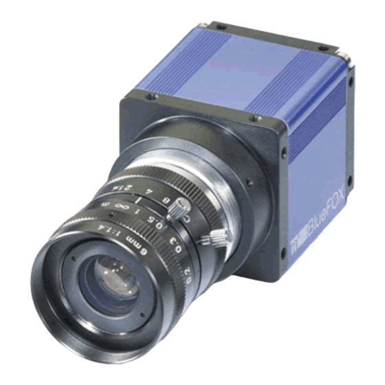
- Page 1 mvBlueFOX Technical Manual English - Version 3.02...
-
Page 3: Table Of Contents
1.1 About this manual ..........1.1.1 Goal of the manual . - Page 4 1.8.1.1 Supported Operating Systems ......1.8.2 Installing the mvIMPACT Acquire driver ......1.8.2.1 Windows .
- Page 5 1.9.5.2 LED states ........1.9.5.3 Positioning tolerances of sensor chip .
- Page 6 1.18.2.3 Working With Gain And Black-Level Values Per Color Channel ... 122 1.18.3 Saving data on the device ........130 1.18.3.1 Creating user data entries .
- Page 7 1.21.1 C.1 ARM64 based devices ........220 1.21.1.1 NVIDIA Jetson AGX Xavier .
-
Page 9: About This Manual
1.1 About this manual 1.1 About this manual 1.1.1 Goal of the manual This manual gives you an overview of the mvBlueFOX, MATRIX VISION's compact USB2 industrial camera fam- ily, its technical data and basic operation of the mvBlueFOX. Programming the device is detailed in a separate documentation, which will be available in an online format. -
Page 10: Imprint
1.2 Imprint MATRIX VISION GmbH Talstrasse 16 DE - 71570 Oppenweiler Telephone: +49-7191-9432-0 Fax: +49-7191-9432-288 Website: https://www.matrix-vision.de E-Mail: • info@matrix-vision.de • jobs@matrix-vision.de Author U. Lansche Date 2020 This document assumes a general knowledge of PCs and programming. Since the documentation is published electronically, an updated version may be available online. For this reason we recommend checking for updates on the MATRIX VISION website. -
Page 11: Legal Notice
1.3 Legal notice 1.3 Legal notice 1.3.1 Introduction The firmware running on MATRIX VISION devices make use of a couple of third party software packages that come with various licenses. This section is meant to list all these packages and to give credit to those whose code helped in the creation of this software: 1.3.2 Introduction The mvIMPACT Acuire SDK and its underlying libraries and drivers as well as some of the applications shipped with... -
Page 12: Libusbk
1.3.7 libusbK The USB3 Vision implementation currently makes use of libusbK ( http://libusbk.sourceforge.net written by Travis Lee Robinson who owns all rights for the source code of all modules belonging to the libusbK framework. 1.3.7.1 libusbK license APPLICABLE FOR ALL LIBUSBK BINARIES AND SOURCE CODE UNLESS OTHERWISE SPECIFIED. PLEASE SEE INDIVIDUAL COMPONENTS LICENSING TERMS FOR DETAILS. -
Page 13: Sha1 Algorithm
1.3 Legal notice 1.3.9 SHA1 algorithm Parts of this framework make use of an open source implementation of the SHA1 algorithm written by Dominik Reichl ( http://www.dominik-reichl.de 1.3.10 Expat Expat is used to parse XML strings within the SDK. 1.3.10.1 Expat Copyright Copyright (c) 1998, 1999, 2000 Thai Open Source Software Center Ltd Permission is hereby granted, free of charge, to any person obtaining a copy of this software and associated documentation files (the "Software"), to deal in the Software without restriction, including without limitation the rights... -
Page 14: Cjson
1.3.13 cJSON A slightly modified version of cJSON is used inside some of the modules that eventually build up the firmware. Copyright (c) 2009 Dave Gamble Permission is hereby granted, free of charge, to any person obtaining a copy of this software and associated documentation files (the "Software"), to deal in the Software without restriction, including without limitation the rights to use, copy, modify, merge, publish, distribute, sublicense, and/or sell copies of the Software, and to permit persons to whom the Software is... -
Page 15: Revisions
1.4 Revisions 1.4 Revisions Date Rev. Author Description Driver / Firmware version 06. December 2022 V3.02 Updated main page . 22. August 2022 V3.01 Removed "L" option of the digital I/Os (mvBlueFOX-MLC (p. 17)) . 03. May 2021 V3.00 Corrected Symbols and Conventions (p. -
Page 16: Symbols And Conventions
1.5 Symbols and Conventions Note This symbol indicates general notes. 1.5.1 Explanation of the warnings Always observe the warnings in these instructions and the measures described to avoid hazards. The warnings used here contain various signal words and are structured as follows: Attention SIGNAL WORD "Type and source of the hazard"... -
Page 17: Important Information
1.6 Important Information 1.6 Important Information We cannot and do not take any responsibility for the damage caused to you or to any other equipment connected to the mvBlueFOX. Similarly, warranty will be void, if a damage is caused by not following the manual. -
Page 18: High-Speed Usb Design Guidelines
1.6.1 High-Speed USB design guidelines If you want to make own High-Speed (HS) USB cables, please pay attention to following design guidelines: • Route High-Speed (HS) USB signals with a minimum number of vias and sharp edges! • Avoid stubs! •... - Page 19 1.6 Important Information MATRIX VISION GmbH...
- Page 20 MATRIX VISION GmbH...
-
Page 21: Legal Notice
1.6 Important Information 1.6.3 Legal notice 1.6.3.1 For customers in the U.S.A. Class B MATRIX VISION GmbH... -
Page 22: For Customers In Canada
This equipment has been tested and found to comply with the limits for a Class B digital device, pursuant to Part 15 of the FCC Rules. These limits are designed to provide reasonable protection against harmful interference when the equipment is operated in a residential environment. This equipment generates, uses, and can radiate radio frequency energy and, if not installed and used in accordance with the instruction manual, may cause harmful interference to radio communications. -
Page 23: Order Code Nomenclature
1.7 Introduction The mvBlueFOX is suitable for following tasks: • machine vision • robotics • surveillance • microscopy • medical imaging With the name mvBlueFOX-M1xx, the industrial camera mvBlueFOX is also available as a single-board version. 1.7.1 Order code nomenclature 1.7.1.1 mvBlueFOX The mvBlueFOX nomenclature scheme is as follows: mvBlueFOX - A B - (1) (2) (3) (4) -
Page 24: Mvbluefox-M
1.7.1.2 mvBlueFOX-M The mvBlueFOX-M nomenclature scheme is as follows: mvBlueFOX-M A B - (1) (2) (3) (4) - A: Sensor model 220: 0.3 Mpix, 640 x 480, 1/4", CCD 220a: 0.3 Mpix, 640 x 480, 1/3", CCD 200w: 0.4 Mpix, 752 x 480, 1/3", CMOS 221: 0.8 Mpix, 1024 x 768, 1/3", CCD 202a: 1.3 Mpix, 1280 x 1024, 1/2", CMOS 223: 1.4 Mpix, 1360 x 1024, 1/2", CCD... -
Page 25: Mvbluefox-Mlc
1.7 Introduction - (3): Case 1: Color blue (standard) 2: Color black, no logo, no label MATRIX VISION 9: None - (4): I/O 1: None (standard) 2: With I/O #08727 1.7.1.4 mvBlueFOX-MLC The mvBlueFOX-MLC nomenclature scheme is as follows: mvBlueFOX-MLC A B - C D E - (1) (2) (3) (4) - A: Sensor model 200w: 0.4 Mpix, 752 x 480, 1/3", CMOS 202b: 1.2 Mpix, 1280 x 960, 1/3", CMOS... -
Page 26: What's Inside And Accessories
is the standard delivery variant and for this reason it is not mentioned. -1111 1.7.2 What's inside and accessories Due to the varying fields of application the mvBlueFOX is shipped without accessories. The package contents: • mvBlueFOX • instruction leaflet For the first use of the mvBlueFOX we recommend the following accessories to get the camera up and running: •... -
Page 27: Quickstart
1.8 Quickstart 1.8 Quickstart • System Requirements (p. 19) • Installing the mvIMPACT Acquire driver (p. 20) • Connecting The Camera (p. 25) • Driver concept (p. 25) • Relationship between driver, firmware and FPGA file (p. 28) • Settings behaviour during startup (p. 32) •... -
Page 28: Installing The Mvimpact Acquire Driver
1.8.1.1.2 Linux Please check the 'Support' section of the MATRIX VISION website for the availability of the latest Linux driver package. See also https://matrix-vision.com/software-drivers-en.html Currently supported Kernel versions are: • Kernel 3.5.x or greater 1.8.2 Installing the mvIMPACT Acquire driver 1.8.2.1 Windows Note Before connecting the mvBlueFOX, please install the software and driver first! - Page 29 1.8 Quickstart mvBlueFOX installer - Select folder Since mvIMPACT Acquire 2.25.0 wxPropView (p. 68) is able to check the availability of new driver versions weekly. Deactivate the check box if wxPropView should not check for updates. You can activate this again in wxPropView (p. 68) via the help menu. mvBlueFOX installer - Select features •...
- Page 30 mvBlueFOX installer - Confirm installation • The installation is finished now you can close the window. mvBlueFOX installer - Finished installation You will find all tools like • wxPropView (p. 68) and • mvDeviceConfigure (p. 68) either as shortcuts on the desktop or in the Windows start menu under "MATRIX VISION - mvIMPACT Acquire".
-
Page 31: Linux
1.8 Quickstart 1.8.2.2 Linux The following (additional) packages will be needed to use all features of mvIMPACT Acquire: • libwxbase3.0-0v5 • libwxbase3.0-dev • libwxgtk3.0-gtk3-0v5 • libwxgtk3.0-gtk3-dev • libwxgtk-webview3.0-gtk3-0v5 • libwxgtk-webview3.0-gtk3-dev • wx3.0-headers • build-essential (meta package) • libgtk2.0-dev • gcc 4.8.5 (4.9.4 for ARM versions) environment or newer Note The names of the packages as mentioned above are the Ubuntu specific ones. - Page 32 The following example explains the installation process for the x86_64 package. The installation process for other packages will work almost identical except different names as mentioned in the previous table. • Please start a console and change into the directory where the installation script and the installation package are located e.g.
-
Page 33: Connecting The Camera
1.8 Quickstart 1.8.3 Connecting The Camera Note Before connecting the mvBlueFOX, please install the software and driver first! After the driver installation you have to connect the mvBlueFOX using a USB 2.0 cable. You can check if the driver installation was successful by using mvDeviceConfigure (p. 68). Supported device with an installed and running driver should be listed: Connected mvBlueFOX Afterwards, you can start wxPropView (p. - Page 34 Driver concept • 1 Part of any mvIMPACT Acquire driver installation package (Windows). • 2 Separately available for 32 bit and 64 bit. Requires at least one installed driver package. • 3 See 2, but requires an installed version of the mvBlueFOX driver. •...
-
Page 35: Neurocheck Support
1.8 Quickstart 1.8.4.1 NeuroCheck Support A couple of devices are supported by NeuroCheck. However between NeuroCheck 5.x and NeuroCheck 6.x there has been a breaking change in the internal interfaces. Therefore also the list of supported devices differs from one version to another and some additional libraries might be required. -
Page 36: Labview Support
MATRIX VISION devices that also comply with the GigE Vision standard don't need any software at all, but can also use HALCON's built-in GigE Vision support. As some mvIMPACT Acquire device driver packages also come with a GenTL compliant interface, these can also be operated through HALCON's built-in GenTL acquisition interface. -
Page 37: Fpga
1.8 Quickstart The firmware file is a binary part of the device driver Note As it can be seen in the image one or multiple firmware files are also a binary part of the device driver. However it is important to notice that this firmware file will NOT be used automatically but only when the user or an application explicitly updates the firmware on the device and will only become active after power-cycling the device. -
Page 38: Firmware
Note There is just a limited set of devices that offer more than one FPGA file and these additional FPGA files serve very special purposes so in almost every situation the default FPGA file will be the one used by an application. - Page 39 1.8 Quickstart During an explicit firmware update, the firmware file from inside the driver will be downloaded onto the device. In order to become active the device must be power-cycled: Firmware file will be downloaded during an firmware update... When then re-attaching the device to the host system, the new firmware version will become active: ...
-
Page 40: Settings Behaviour During Startup
wxPropView - FPGA and Firmware version numbers 1.8.6 Settings behaviour during startup A setting contains all the parameters that are needed to prepare and program the device for the image capture. Every image can be captured with completely different set of parameters. In almost every case, these parameters are accessible via a property offered by the device driver. - Page 41 1.8 Quickstart wxPropView - Device setting start procedure • Please note that each setting location step in the figure from above internally contains two search steps. First the framework will try to locate a setting with user scope and if this can't be located, the same setting will be searched with global (system-wide) scope.
-
Page 42: Optimizing Usb Performance
• A detailed description of the individual properties offered by a device will not be provided here but can be found in the C++ API reference, where descriptions for all properties relevant for the user (grouped together in classes sorted by topic) can be found. As wxPropView (p. 68) doesn't introduce new functionality but simply evaluates the list of features offered by the device driver and lists them any modification made using the GUI controls just calls the underlying function needed to write to the selected component. -
Page 43: Using Mvbluefox Cameras In A Docker Container
1.8 Quickstart SUBSYSTEM!="usb|usb_device|plugdev", GOTO="mvbf_rules_end" ACTION!="add", GOTO="mvbf_rules_end" ATTRS{idVendor}=="164c", ATTRS{idProduct}=="5531", MODE="0664", GROUP="plugdev" LABEL="mvbf_rules_end" Note The above 52-U3V.rules file provides the necessary access privileges not only for mvBlueFOX cameras, but also for any "USB3 Vision"-compliant device of other vendors. As soon as this file is into place, each time the camera is plugged to the system it acquires the set of rights that allows the user to use it without having root privileges. -
Page 44: Building A Docker Image
1.8.8.1.2.3 Start udev manually udev is needed to identify attached USB devices and to access USB3 Vision™ devices as non-root users with the help of the udev-rules shipped by the mvIMPACT Acquire driver package. How- ever, systemd, which starts udev automatically, is by default not supported in WSL2 distros. Besides, udev doesn't support containers. -
Page 45: Starting The Docker Container
1.8 Quickstart # start with slim version of actual Debian FROM debian:9-slim ENV LC_ALL C ENV DEBIAN_FRONTEND noninteractive # entrypoint of Docker CMD ["/bin/bash"] # set environment variables ENV TERM linux ENV MVIMPACT_ACQUIRE_DIR /opt/mvIMPACT_Acquire ENV MVIMPACT_ACQUIRE_DATA_DIR /opt/mvIMPACT_Acquire/data ENV container docker # update packets and install minimal requirements # after installation it will clean apt packet cache RUN apt-get update &&... -
Page 46: Validation
1.8.8.4 Validation After starting the container, the correct operation of mvBlueFOX cameras can be validated by running one of the sample programs provided by the mvIMPACT Acquire (e.g. SingleCapture): $ cd /opt/mvIMPACT_Acquire/apps/SingleCapture/x86_64 $ ./SingleCapture If the attached mvBlueFOX camera appears in the device list of the program's output, access to it in the container by using the mvIMPACT Acquire has been established. - Page 47 1.9 Technical Data Figure 2: Dimensional drawing of tripod adapter 1.9.2.1.1 D-Sub 9-pin (male) Figure 3: D-Sub 9-pin (male), digital I/O Signal Description IN0- Negative terminal of opto-isolated input OUT0- Negative terminal of opto-isolated output (emitter of npn-phototransistor) OUT1- Negative terminal of opto-isolated output (emitter of npn-phototransistor) IN1- Negative terminal of opto-isolated input IN0+...
- Page 48 Figure 4: DigIn mvBlueFOX-xxx In wxPropView (p. 68) you can change between • TTL ( "DigitalInputThreshold = 2V" ) and • PLC ( "DigitalInputThreshold = 10V" input behavior of the digital inputs using the DigitalInputThreshold property in "Digital I/O - DigitalInput Threshold": Figure 5: wxPropView - DigitalInputThreshold...
- Page 49 1.9 Technical Data Figure 6: DigOut mvBlueFOX-xxx 1.9.2.1.1.3 Connecting flash to digital output You can connect a flash in series to the digital outputs as shown in the following figure, however, you should only use LEDs together with a current limiter: Figure 7: Connecting flash (LEDs) to DIG OUT 1.9.2.1.2 USB connector, type B (USB 2.0) Figure 8: USB B connector (female)
-
Page 50: Led States
Note The mvBlueFOX is an USB device! Attention "Surge" Using both USB ports at the same time can damage the device. Do not connect both USB ports at the same time. 1.9.2.1.3 4-pin circular plug-in connector with lock (USB 2.0) Figure 9: 4-pin circular plug-in connector (female) Signal 'R' version Signal 'U' version... -
Page 51: Components
1.9 Technical Data State Camera is not connected or defect LED off Camera is connected and active Green light on 1.9.2.3 Components • FPGA for image processing • pixel clock up to 40 MHz • reliable image transfer – using bulk-mode –... -
Page 52: Board-Level Version (Mvbluefox-Mxxx)
1.9.3 Board-level version (mvBlueFOX-Mxxx) 1.9.3.1 Dimensions and connectors Figure 10: mvBlueFOX-M12x (CCD) with C-mount Figure 11: mvBlueFOX-M10x (CMOS) Lens mount Type "FB" C-Mount 17.526 MATRIX VISION GmbH CS-Mount 12.526... - Page 53 1.9 Technical Data Figure 12: Backside view of the board Note The mvBlueFOX-M has a serial I²C bus EEPROM with 64 KBit of which 512 Bytes can be used to store custom arbitrary data. See also UserDataEntry class description Signal Comment Cable USBPOWER_IN...
- Page 54 1.9.3.1.2 12-pin Wire-to-Board header (Dig I/O) Manufacturer: JST Part number: B12B-PH-K Attention "False tensions or short-circuits" The digital I/O's are connected directly via a resistor to the FPGA pins and therefore they are not protected. If you connect the digital I/Os without providing a protection you will risk damaging the device. - Provide a protection circuit to the digital I/O's of mvBlueFOX-M.
- Page 55 1.9 Technical Data Circuits Dimensions in mm (in.) Q'ty / box 6.0 (.236) 9.8 (.386) 1.000 22.0 (.866) 25.8 (1.016) 1.000 Material and finish: nylon 66, UL94V-0, natural (white) Manufacturer: JST Part number: PHR-4 / PHR-12 See also Suitable assembled cable accessories for mvBlueFOX-M: What's inside and accessories (p. 18) 1.9.3.1.5 Characteristics of the mvBlueFOX-Mxxx digital I/Os Symbol Comment...
-
Page 56: Led States
Symbol Comment Unit current at digital output +-12 +-24 DIG_OUT digital output (I =12mA) DIG_OUT_HIGH Digital output (I 2mA) digital output (I =2mA) DIG_OUT_LOW 1.9.3.1.5.3 Characteristics of the digital outputs U = 2.8 - I DIG_OUT_HIGH min Figure 16: Digital output mvBlueFOX-Mxxx Attention "False tensions or short-circuits"... -
Page 57: Accessories Mvbluefox-Mxxx
1.9 Technical Data 1.9.3.4 Accessories mvBlueFOX-Mxxx 1.9.3.4.1 mvBlueFOX-M-FC-S The mvBF-M-FC-S contains high capacity condensers with switching electron- ics for transferring stored energy of the condensers to external flash LEDs. It is possible to connect 2 pushbut- tons/switches to the 8-pin header (CON3 - Control connector). Additionally, 2 LED interfaces are available. There are two version of mvBF-M-FC-S: •... - Page 58 Figure 18: Model 2 with CON1 connector Signal Comment Flash + Flash power Flash - Switched to ground (low side switch) 1.9.3.4.1.1 CON2 - Flash connector Manufacturer: JST Part number: B-2B-PH Signal Comment LED2 cathode connector / board ground LED2 output LED2 anode connector1 LED1 cathode connector / board ground LED1 output...
-
Page 59: Single-Board Version (Mvbluefox-Mlc2Xx)
1.9 Technical Data Internal series resistance 465. 474. Forward current I at U = 2V Voltage (open contact) (low level input voltage) Input 1/2 (internal 10k pull up to 3.3V) (high level input voltage) Voltage (open contact) Flash output capacitance Flash + Internal capacitance storage energy 0.190... -
Page 60: Dimensions And Connectors
1.9.4.2 Dimensions and connectors Figure 20: mvBlueFOX-MLCxxxx-XOW-1111 Note The mvBlueFOX-MLC has a serial I²C bus EEPROM with 16 KByte of which 8 KByte are reserved for the firmware and 8 KByte can be used to store custom arbitrary data. See also UserDataEntry class description 1.9.4.2.1 Sensor's optical midpoint and orientation The sensor's optical midpoint is in the center of the board (Figure 21: intersection point of the holes diagonals). - Page 61 1.9 Technical Data 1.9.4.2.2 Mini-B USB (USB 2.0) Figure 22: Mini-B USB Signal Comment USBPOWER_IN Supply voltage USB_DATA- Data USB_DATA+ Data Not connected Ground 1.9.4.2.3 12-pin Wire-to-Board header (USB 2.0 / Dig I/O) Note If you have the mvBlueFOX-MLC variant which uses the standard Mini-B USB connector, pin 2 and 3 (USB_DATA+ / USB_DATA-) of the header won't be connected! Opto-isolated variant TTL compliant variant...
- Page 62 OUT0- Opto-isolated OUT1 TTL compliant blue blue digital output digital output 1 (Negative voltage) OUT0+ Opto-isolated OUT0 TTL compliant violet violet digital output digital output 0 (Positive voltage) IN0- Opto-isolated TTL compliant gray gray digital input digital input 1 (Negative voltage) IN0+ Opto-isolated...
- Page 63 1.9 Technical Data Note If the digital input is not connected, the state of the input will be "1" (as you can see in wxPropView (p. 68)). TTL compliant variant Comment Unit (INx) LVTTL compliant variant Comment Unit (INx) TTL input low level / high level time: Typ. 210ns Digital outputs TTL Figure 24: TTL digital outputs block diagram...
- Page 64 Figure 25: Opto-isolated digital inputs block diagram with example circuit Delay Characteristics Symbol Typ. Unit Turn-On time The inputs can be connected directly to +3.3 V and 5 V systems. If a higher voltage is used, an external resistor must be placed in series (Figure 25). Used input voltage External series resistor 3.3V ..
-
Page 65: Led States
1.9 Technical Data Figure 27: Output switching times Characteristics Symbol Test conditions Typ. Unit Turn-On time Storage time = 100 Ohm, V 10V, I = 2mA Turn-Off time Turn-On time Storage time = 1.9 kOhm, V 5V, I = 16mA Turn-Off time Comment Unit... -
Page 66: Single-Board Version With Housing (Mvbluefox-Igc2Xx)
• C(S)-mount compatibility using mvBlueCOUGAR-X flange • ambient temperature operation: 5..55 deg C / 30..80 RH • ambient temperature storage: -25..60 deg C / 20..90 RH 1.9.5 Single-board version with housing (mvBlueFOX-IGC2xx) 1.9.5.1 Dimensions and connectors Figure 28: mvBlueFOX-IGC Lens protrusion C-Mount CS-Mount 10 mm... -
Page 67: Led States
1.9 Technical Data See also UserDataEntry class description 1.9.5.1.1 Mini-B USB (USB 2.0) Figure 30: Mini-B USB Signal Comment USBPOWER_IN Supply voltage USB_DATA- Data USB_DATA+ Data Not connected Ground 1.9.5.1.2 4-pin circular plug-in connector with lock (I/O) Figure 31: 4-pin circular plug-in connector (female) Signal Comment Color (of cable) -
Page 68: Positioning Tolerances Of Sensor Chip
State Camera is not connected or defect LED off Camera is connected but not initialized or in "Power off" mode. Orange light on Camera is connected and active Green light on 1.9.5.3 Positioning tolerances of sensor chip The sensor's optical midpoint is in the center of the housing. However, several positioning tolerances in relation to the housing are possible because of: •... -
Page 69: Sensor Overview
1.10 Sensor Overview Note There are also tolerances in lens which could lead to optical offsets. 1.10 Sensor Overview By default, the steps exposure and readout out of an image sensor are done one after the other. By design, CCD sensors support overlap capabilities also combined with trigger (see figure). - Page 70 Sensors Mpixels Mpixels Mpixels Mpixels Mpixels resolution CCD resolution CCD resolution CCD resolution CCD resolution CCD sensor (-220) sensor (-220a) sensor (-221) sensor (-223) sensor (-224) Sensor supplier Sony Sony Sony Sony Sony Sensor name ICX098 AL/BL ICX424 AL/AQ ICX204 AL/AQ ICX267 AL/AQ ICX274 AL/AQ Resolution...
-
Page 71: Cmos Sensors
1.10 Sensor Overview Pipelined X / - X / - X / - X / - X / - continuous triggered mode Flash con- trol output, synchronous exposure period More specific mvBlueFOX- mvBlueFOX- mvBlueFOX- mvBlueFOX- mvBlueFOX- data [Model]220 [Model]220a [Model]221 [Model]223 [Model]224 (0.3 Mpix [640... - Page 72 Exposure 10 us - 0.46 s 100 us - 10 s 10 us - 1 s 10 us - 1 s 10 us - 1 s 10 us - 10 s time ADC resolu- 10 bit (10 / 8 10 bit (10 / 8 10 bit (10 / 8 10 bit (10 / 8 10 bit (10 / 8...
-
Page 73: Output Sequence Of Color Sensors (Rgb Bayer)
1.10 Sensor Overview Note For further information about rolling shutter, please have a look at the practical report about rolling shutter on our website: https://www.matrix-vision.com/tl_files/mv11/ Glossary/art_rolling_shutter_en.pdf For further information about image errors of image sensors, please have a look at For further information about image errors of image sensors, please have a look at Correcting image errors of a sensor (p. -
Page 74: Filters
(G1+G3+G11+G13) G7_new = 0.5 * G7 + 0.5 * --------------- 2. Interpolation of red/blue pixels: Interpolation of a red/blue pixel at a green position: the average of two adjacent pixel values in corresponding color is assigned to the interpolated pixel. For example: (B6+B8) (R2+R12) -
Page 75: Cold Mirror Filter
1.11 Filters Figure 1: FILTER IR-CUT 15,5X1,75 FE wavelengths and transmission diagram 1.11.2 Cold mirror filter The FILTER DL-CUT 15,5X1,5 is a high-quality day light cut filter and has optically polished surfaces. The polished surface allows the use of the filter directly in the path of rays in image processing applications. The filter is protected against scratches during the transport by a protection film that has to be removed before the installing the filter. -
Page 76: Glass Filter
Note For further information how to change the filter, please have a look at our website: https://www.matrix-vision.com/tl_files/mv11/Glossary/art_optical_ filter_en.pdf 1.11.3 Glass filter It is also possible to choose the glass filter "FILTER GLASS 15,5X1,75" with following characteristics: Technical data Glass thickness 1.75 mm Material Borofloat without coating... -
Page 77: Mvgigeconfigure
1.12 GUI tools 1.12.5 mvGigEConfigure With mvGigEConfigure it is possible • to install, remove or configure the MATRIX VISION GigE Vision™ capture filter driver. See also For further information about the tools, please follow the link to the separate manual describing the GUI tools in great detail on our website: https://www.matrix-vision.com/manuals/ MATRIX VISION GmbH... -
Page 78: Hrtc - Hardware Real-Time Controller
1.13 HRTC - Hardware Real-Time Controller 1.13.1 Introduction The Hardware Real-Time Controller (HRTC) is built into the FPGA. The user can define a sequence of operating steps to control the way how and when images are exposed and transmitted. Instead using an external PLC, the time critical acquisition control is directly build into the camera. - Page 79 1.13 HRTC - Hardware Real-Time Controller Figure 1: wxPropView - Setting up the HRTC usage Following trigger modes can be used with HRTC: • OnLowLevel • OnHighLevel • OnFallingEdge • OnRisingEdge • OnHighExpose Further details about the mode are described in the API documentation: See also TCameraTriggerMode and TCameraTriggerSource in •...
-
Page 80: Developing Applications Using The Mvimpact Acquire Sdk
1.14 Developing applications using the mvIMPACT Acquire SDK mvIMPACT Acquire SDK is a comprehensive software library that can be used to develop applications using the devices described in this manual. A wide variety of programming languages is supported. For C, C++, .NET, Python or Java developers separate API descriptions can be found on the MATRIX VISION website: •... -
Page 81: Directshow Interface
1.15 DirectShow interface 1.15 DirectShow interface Note DirectShow can only be used in combination with the Microsoft Windows operating system. Since Windows Vista, Movie Maker does not support capturing from a device registered for DirectShow anymore. This is the documentation of the MATRIX VISION DirectShow_acquire interface. A MATRIX VISION specific prop- erty interface based on the IKsPropertySet has been added. - Page 82 delete [] prop_array[pr].stringArray; //------------------------------------------------------------------------------ // scanning the property list props for a property with name property_name MVProperty * GetProperty( MVProperty * props, unsigned int property_count, char * property_name ) //------------------------------------------------------------------------------ for( unsigned int pr = 0; pr < property_count && props != 0; pr++ ) // please feel free to replace standard c string handling to Standard C++ Library strings if( strcmp( props[pr].propertyName, property_name ) == 0 ) return...
-
Page 83: Logging
1.15 DirectShow interface if( SUCCEEDED( hr ) ) const max_prop = 500; MVProperty props[max_prop]; unsigned int propCnt = ScanAllProperties( gcap.pVSC, props, max_prop ); // if successful we get a list something like this otherwise propCnt = 0 //... //props[0x40] {propertyName="ImagingSubsystem/Setting/Base/Camera/AutoExposeControl" value={s= "Off"... -
Page 84: Registering Devices
1.15.3.1 Registering devices To register all devices currently recognized by the mvIMPACT Acquire driver stack for access with DirectShow the following registration procedure is needed: mvDeviceConfigure needs to be started(with elevated rights). If no device has been registered the application will more or less (depending on the installed devices) look like this. - Page 85 1.15 DirectShow interface mvDeviceConfigure - Register All Devices 3. After a successful registration the column "Registered For DirectShow" will display "yes" for every device and the devices will be registered with a default DirectShow friendly name which is displayed in the "DirectShow Friendly Name"...
-
Page 86: Renaming Devices
1.15.3.2 Renaming devices To modify the DirectShow friendly name of a device: 1. mvDeviceConfigure needs to be started(with elevated rights). 2. right-click on the device to rename and select "Set DirectShow Friendly Name": mvDeviceConfigure - Set DirectShow Friendly Name 3. Then, a dialog will appear. Please enter the new name and confirm it with "OK". mvDeviceConfigure - Dialog For New Name 4. -
Page 87: Using Regsvr32
1.15 DirectShow interface mvDeviceConfigure - Renamed Device Note Please do not select the same friendly name for two different devices. In theory this is possible, however the mvDeviceConfigure GUI will not allow this to avoid confusion. 1.15.3.3 Using regsvr32 To register all devices currently recognized by the mvIMPACT Acquire driver stack with auto-assigned names, the Windows tool "regsvr32"... -
Page 88: Troubleshooting
1.16 Troubleshooting • Accessing log files (p. 80) 1.16.1 Accessing log files If you need support using our products, you can shorten response times by sending us your log files. Accessing the log files is different in Windows and Linux: 1.16.1.1 Windows Since mvIMPACT Acquire 2.11.9... -
Page 89: Glossary
1.17 Glossary user@linux-desktop:~$ // <- Starting the console window, you will be in the home directory: /home/ user@linux-desktop:~$ cd workspace/apps/ // <- Change the directory user@linux-desktop:/home/workspace/apps$ ls -l // <- List the directory insgesamt 144 drwxr-xr-x 9 user user 4096 Mai 21 15:08 Callback drwxr-xr-x 8 user user 4096 Mai 21 15:08 Callback_C... - Page 90 A group line via which the various parts of the computer communicate with one another. Configurable monolithic application including shell and other useful BusyBox command line tools - often called the "swiss army knife" for embedded systems. Even desktop distributions are sometimes relying on BusyBox due to its robustness.
- Page 91 1.17 Glossary GenTL is the transport layer interface for GenTL cameras, acquiring images from the camera, and moving them to the user application. The term Gigabit Ethernet (defined by the Gigabit Ethernet (GigE) IEEE 802.3-2008 standard) represents various technologies for transmitting Ethernet frames at a rate of a gigabit per second (1,000,000,000 bits per second).
- Page 92 GigE Vision is a network protocol designed for the GigE Vision communication between an imaging device and an application. This proto- col completely describes: • device discovery • data transmission – image data – additional data • read/write of parameters. GigE Vision uses UDP for data transmission to reduce overhead in- troduced by TCP.
- Page 93 1.17 Glossary High Dynamic Range (HDR) The HDR (High Dynamic Range) mode increases the usable contrast range. This is achieved by dividing the integration time in two or three phases. The exposure time proportion of the three phases can be set independently. Furthermore, it can be set, how many signal of each phase is charged.
- Page 94 Logical link address (LLA) is a type of mechanism to obtain a valid IP address without a DHCP server being present. Whether an IP address is available or not is resolved using address resolution protocol (ARP) packets. If no ARP response is received on a given address it is considered unused and will be assigned to the interface.
- Page 95 1.17 Glossary In the tab "IPv4 Setting" you have to set "Link-Local Only": After saving, you will find both connections in the summary: Now, you can select the wished connection using the left mouse button in the "Network Manager" menu. In the LLA case it is just the new created connection: Look-up table Table of assignments.
- Page 96 Look-up table Media Access Control address (MAC address) is MAC address a quasi-unique identifier attached to most network adapters (NICs) in computer networking. Maximum transmission unit (MTU) refers to the size (in bytes) of the largest packet that a given layer of a communications protocol can pass onwards.
- Page 97 1.17 Glossary By default, the steps exposure and readout out of an image sensor are Overlapped / pipelined transfer done one after the other. • By design, CCD sensors support overlap capabilities also combined with trigger (see figure). • In contrast, so-called pipelined CMOS sensors only support the over- lapped mode.
- Page 98 Standard Feature Naming Convention SFNC of GenICam (p. 82). See also latest GenICam properties list found here: http://www.emva. org/standards-technology/genicam/genicam-downloads/ The file is called "GenICam Standard Features Naming Convention (PDF)" In computing, a shell is a piece of software that provides an Shell interface for users.
-
Page 99: Use Cases
1.18 Use Cases 1.18 Use Cases • Introducing acquisition / recording possibilities (p. 92) • Improving the acquisition / image quality (p. 104) • Saving data on the device (p. 130) • Working with several cameras simultaneously (p. 132) • Working with HDR (High Dynamic Range Control) (p. 138) •... -
Page 100: Introducing Acquisition / Recording Possibilities
1.18.1 Introducing acquisition / recording possibilities There are several use cases concerning the acquisition / recording possibilities of the camera: • Generating very long exposure times (p. 92) • Using Video Stream Recording (p. 93) 1.18.1.1 Generating very long exposure times Since mvIMPACT Acquire 1.10.65 Very long exposure times are possible with mvBlueFOX. -
Page 101: Using Video Stream Recording
1.18 Use Cases 1.18.1.2 Using Video Stream Recording With the FFmpeg libraries it is possible to record an mvIMPACT Acquire image stream into a compressed video stream. Since 2.39.0 1.18.1.2.1 Requirements Since the mvIMPACT Acquire API internally uses FFmpeg to record video streams, the FFmpeg libraries need to be present on the target system as well. - Page 102 Figure 2: Click 'Video Stream Recording...' 3. A setup dialog will then be initialized as follows. Please read the setup hints in the text box for more informa- tion. MATRIX VISION GmbH...
- Page 103 1.18 Use Cases Figure 3: Video stream recording setup dialog 4. Enable the video stream recording mode. Choose a pixel format (e.g. 'YUV422Packed' or 'YUV422Planar') that will be generated by the device driver and used by FFmpeg for video stream encoding. Then click on 'Select an output file' to create/choose a file to hold the recorded video stream.
- Page 104 Figure 4: Enable the video stream recording mode and set up device driver related parameters 5. In the file selector, choose a file type (e.g. ' .mp4' or ' .m2v') and enter a file name. MATRIX VISION GmbH...
- Page 105 1.18 Use Cases Figure 5: Select an output file 6. Set up video stream related parameters accordingly. In the check boxes below, users are allowed to choose whether to synchronize acquisition stop with recording stop and whether to overwrite the already recorded video stream if the currently selected output file has the same file name as the previous one.
- Page 106 Figure 6: Set up video stream related parameters 7. Once the video stream recording has been set up, click 'Apply' or 'Ok' to apply the current settings. Afterwards, a log message in the analysis output will indicate whether the current settings have been applied successfully. If successful, the 'Start' control button at the top right tool-bar will be enabled.
- Page 107 1.18 Use Cases Figure 7: Apply the current settings Note When deactivating the video stream recording, uncheck the 'Enable video stream recording mode' and then click 'Apply' or 'Ok' for the settings to take effect. Once the settings have been applied, users can control the recording process via the 'Start', 'Pause' and 'Stop' buttons: •...
- Page 108 Figure 8: Start recording • Pause recording: Click the 'Pause' button to pause a running recording. The current recording status will be displayed in the analysis output. Figure 9: Pause recording MATRIX VISION GmbH...
- Page 109 1.18 Use Cases • Resume recording: Click the 'Pause' button to resume a paused recording. The current recording status will be displayed in the analysis output. Figure 10: Resume recording • Stop recording: Click the 'Stop' button to stop recording the video stream. The current recording status and information will be displayed in the analysis output.
- Page 110 Figure 11: Stop recording When recording to an output file which has the same file name as the previous one while overwriting the recorded content is not desired: 1. When clicking 'Start', a file selector will pop up to ask users to create a new output file with the same file type as the previous one.
- Page 111 1.18 Use Cases Figure 13: Start recording to an output file with the same file name as the previous one without overwriting 1.18.1.2.3 Recording Using The API Please refer to the example on how to record a video stream using mvIMPACT Acquire C++ API: Continuous or have a look at the class.
-
Page 112: Improving The Acquisition / Image Quality
1.18.2 Improving the acquisition / image quality There are several use cases concerning the acquisition / image quality of the camera: • Correcting image errors of a sensor (p. 104) • Optimizing the color/luminance fidelity of the camera (p. 113) •... - Page 113 1.18 Use Cases 1.18.2.1.2 Defect pixel detection using mvIMPACT Acquire As mentioned, the defect pixel list can be gener- ated using mvIMPACT Acquire. Since there are three types of defects, mvIMPACT Acquire offers three calibration methods for detection: 1. leaky pixel (in the dark) which indicates pixels that produce a higher read out code than the average 2.
- Page 114 The filter checks: Pixel > T[hot] // (default value: 15 %) // T[hot] = deviation of the average gray value Pixel < T[cold] // (default value: 15 %) // T[cold] = deviation of the average gray value Note Repeating the defective pixel corrections will accumulate the correction data which leads to a higher value in "DefectivePixelsFound"...
- Page 115 1.18 Use Cases The section "Setting - Base - ImageProcessing - DefectivePixelsFilter" was also extended (see Figure 2). First, "DefectivePixelsFound" indicates the number of found defective pixels. The coordinates are available through the properties "DefectivePixelOffsetX" "DefectivePixelOffsetY" now. In addition to that it is possible to edit, add and delete these values manually (via right-click on the "DefectivePixel and select "Append Value"...
- Page 116 Figure 3: Defective pixel data are written to the camera (since driver version 2.17.1 and firmware version 2.12.406) While opening the camera, the camera will load the defective pixel data from the camera. If there are pixels in the filter available (via calibration), nevertheless you can load the values from the camera. In this case the values will be merged with the existing ones.
- Page 117 1.18 Use Cases 1.18.2.1.5 List-based defect Pixel correction on the camera As described before, it is possible to upload lists of defect pixel onto the camera. Different algorithms can be used to determine whether a pixel is defective or not, which is dependent of how much it is allowed a pixel to deviate, temperature, gain, and exposure time.
- Page 118 Note Flat-field correction can also be used as a destructive watermark and works for all f-stops. To make a flat field correction following steps are necessary: 1. You need a plain and equally "colored" calibration plate (e.g. white or gray) 2.
- Page 119 1.18 Use Cases Figure 4: Image corrections: Host-based flat field correction 1.18.2.1.7.1 Host-based Flat-Field Correction With Calibration AOI In some cases it might be necessary to use just a specific area within the camera's field of view to calculate the correction values.
- Page 120 Figure 5: Image corrections: Host-based flat field correction with calibration AOI 1.18.2.1.7.2 Host-based Flat-Field Correction With Correction AOI In some cases it might be necessary to correct just a specific area in the camera's filed of view. In this case the correction values are only applied to a specific area.
-
Page 121: Optimizing The Color/Luminance Fidelity Of The Camera
1.18 Use Cases 1.18.2.2 Optimizing the color/luminance fidelity of the camera Purpose of this chapter is to optimize the color image of a camera, so that it looks as natural as possible on different displays and for human vision. This implies some linear and nonlinear operations (e.g. display color space or Gamma viewing LUT) which are normally not necessary or recommended for machine vision algorithms. - Page 122 Figure 1: Color chart as a starting point If we take a SingleFrame image without any color optimizations, an image can be like this: Figure 2: SingleFrame snap without color optimization Figure 3: Corresponding histogram of the horizontal white to black profile As you can see, •...
- Page 123 1.18 Use Cases Note You have to keep in mind that there are two types of images: the one generated in the camera and the other one displayed on the computer monitor. Up-to-date monitors offer different display modes with different color spaces (e.g. sRGB). According to the chosen color space, the display of the colors is different.
- Page 124 You can change the gain via wxPropView (p. 68) like the following way: 1. Click on "Setting - Base - Camera". There you can find (a) "AutoGainControl" and (b) "AutoExposeControl". Figure 5: wxPropView: Setting - Base - Camera You can turn them "On" or "Off". Using the auto controls you can set limits of the auto control; without you can set the exact value.
- Page 125 1.18 Use Cases Figure 6: After gamma correction Figure 7: Corresponding histogram after gamma correction Note As mentioned above, you can do a gamma correction via ("Setting - Base - ImageProcessing - LUTOperations"): MATRIX VISION GmbH...
- Page 126 Figure 8: LUTOperations dialog Just set "LUTEnable" to "On" and adapt the single LUTs like (LUT-0, LUT-1, etc.). 1.18.2.2.2 Step 2: White Balance As you can see in the histogram, the colors red and blue are below green. Using green as a reference, we can optimize the white balance via "Setting - Base - ImageProcessing"...
- Page 127 1.18 Use Cases Figure 9: After white balance Figure 10: Corresponding histogram after white balance 1.18.2.2.3 Step 3: Contrast Still, black is more a darker gray. To optimize the contrast you can use "Setting - Base - ImageProcessing - LUTControl" as shown in Figure 8. The image will look like this now: Figure 11: After adapting contrast MATRIX VISION GmbH...
- Page 128 Figure 12: Corresponding histogram after adapting contrast 1.18.2.2.4 Step 4: Saturation and Color Correction Matrix (CCM) Still saturation is missing. To change this, the "Color Transformation Control" can be used ("Setting - Base - ImageProcessing - ColorTwist"): 1. Click on "Color Twist Enable" and 2.
- Page 129 1.18 Use Cases Figure 14: Saturation via Color Transformation Control dialog 4. Afterwards, click on "Enable". 5. Since driver version 2.2.2, it is possible to set the special color correction matrices at (a) the input (sensor), (b) the output side (monitor) and (c) the saturation itself using this wizard.
-
Page 130: Working With Gain And Black-Level Values Per Color Channel
Figure 16: Corresponding histogram after adapting saturation 1.18.2.3 Working With Gain And Black-Level Values Per Color Channel In many low-lighting applications the gain needs to be increased to enhance the brighness of the images. However, while the image brightness is increased, the black-level of the image is also increased, which in many cases should be avoided. - Page 131 1.18 Use Cases 1.18.2.3.1 Configuration in wxPropView Here is how to configure the GainOffsetKnee filter in wxPropView and the impact the filter has on an image: 1. The GainOffsetKnee filter is located under "Setting - Base - ImageProcessing". Figure 2: The GainOffsetKnee filter option in wxPropView 2.
- Page 132 Figure 4: An image without the GainOffsetKnee filter Figure 5: The histogram of Figure 3 3. The overall offset can be assigned using the 'GainOffsetKneeMasterOffset_pc'. A positive offset increases the black-level of the image, whereas a negative offset reduces it. To visualize the effect, an offset of 5% is given as an example, which means that the overall black-level of the image will be increased by 5% of the max.
- Page 133 1.18 Use Cases Figure 6: Assign overall/master offset to the image Figure 7: The image with 5% overall offset MATRIX VISION GmbH...
- Page 134 Figure 8: The histogram with 5% overall offset 4. Among the GainOffsetKneeChannels there are 4 channels. For mono images, only channel 0 is used. For RGB images, channel 0-2 are used: red channel, green channel and blue channel respectively. For Bayer images, channel 0-3 are used.
- Page 135 1.18 Use Cases Figure 10: The image with 1.0625dB gain in the red channel Figure 11: The histogram with 1.0625dB gain in the red channel 5. The individual black-level can be assigned using the channel specific 'Offset_pc'. Analogous to 'GainOffset KneeMasterOffset_pc', a positive offset increases the black-level of the channel, whereas a negative offset reduces it.
- Page 136 Figure 12: Assign individual offset to the red channel Figure 13: The image with 5% offset in the red channel MATRIX VISION GmbH...
- Page 137 1.18 Use Cases Figure 14: The histogram with 5% offset in the red channel 1.18.2.3.2 Configuration Using The API Depending on the programming language you are working with the names of classes, namespaces and properties might vary slightly. For C++ please refer to the GainOffset KneeChannelParameters class and the...
-
Page 138: Saving Data On The Device
1.18.3 Saving data on the device Note As described in "Storing, Restoring And Managing Settings" in the "mvIMPACT Acquire SDK GUI Applications" manual, it is also possible to save the settings as an XML file on the host sys- tem. You can find further information about for example the XML compatibilities of the different driver versions in the mvIMPACT Acquire SDK manuals and the according setting classes: https ://www.matrix-vision.com/manuals/SDK_CPP/classmvIMPACT_1_1acquire_1... - Page 139 1.18 Use Cases • "DeleteUserDataEntry" • "WriteDataToHardware" Figure 1: wxPropView - section "UserData - Entries" To create a user data entry, you have to • Right click on "CreateUserDataEntry" • Select "Execute" from the popup menu. An entry will be created. •...
-
Page 140: Working With Several Cameras Simultaneously
Figure 2: wxPropView - analysis tool "Output" 1.18.3.1.2 Coding sample If you e.g. want to use the UserData as dongle mechanism (with binary data), it is not suggested to use wxPropView (p. 68). In this case you have to program the handling of the user data. See also mvIMPACT::acquire::UserDataEntry in mvIMPACT_Acquire_API_CPP_manual.chm. - Page 141 1.18 Use Cases Note Alternatively, it is also possible to use HRTC - Hardware Real-Time Controller (p. 70) HRTC to set the master camera. The following sample shows the HRTC - Hardware Real-Time Controller (p. 70) HRTC program which sets the trigger signal and the digital output. The sample will lead to a constant frame rate of 16 fps (50000 us + 10000 us = 60000 us for one cycle.
- Page 142 Figure 2: wxPropView - HRTC program sets the trigger signal and the digital output Do not forget to set HRTC as the trigger source for the master camera. MATRIX VISION GmbH...
- Page 143 1.18 Use Cases Figure 3: wxPropView - HRTC is the trigger source for the master camera 3. Then, set the slave with wxPropView (p. 68) : Figure 4: wxPropView - Slave camera with TriggerMode "OnHighLevel" at DigIn 0 1.18.4.1.1.1 Connection using -UOW versions (opto-isolated inputs and outputs) The connection of the mvBlueFOX cameras should be like this: MATRIX VISION GmbH...
- Page 144 Figure 5: Connection with opto-isolated digital inputs and outputs Symbol Comment Input voltage Unit External power ext. Resistor digital output kOhm 3.3 V .. 5 V kOhm Resistor digital input 12 V 0.68 kOhm 24 V kOhm You can add further slaves. 1.18.4.1.1.2 Connection using -UTW versions (TTL inputs and outputs) The connection of the mvBlueFOX cameras should be like this: Figure 6: Connection with TTL digital inputs and outputs...
-
Page 145: Synchronize The Cameras To Expose At The Same Time
1.18 Use Cases Note There a no further slaves possible. See also • Dimensions and connectors (p. 52) Figure 18 pin reference. • Dimensions and connectors (p. 52) Table of connector pin out of "12-pin through-hole type shrouded header (USB / Dig I/O)". •... -
Page 146: Working With Hdr (High Dynamic Range Control)
Figure 2: wxPropView - Setup for sync. cameras This assumes that the image acquisition shall start with the rising edge of the trigger signal. Every camera must be configured like this. Each rising edge of the external trigger signal then will start the exposure of a new image at the same time on each camera. - Page 147 1.18 Use Cases 1.18.5.1.2 Functionality Figure 1: Diagram of the -x00w sensor's HDR mode 1.18.5.1.2.1 Description • "Phase 0" – During T1 all pixels are integrated until they reach the defined signal level of Knee Point 1. – If one pixel reaches the level, the integration will be stopped. –...
- Page 148 Figure 2: Integration time of different bright pixels In the diagram you can see the signal line of three different bright pixels. The slope depends of the light intensity , thus it is per pixel the same here (granted that the light intensity is temporally constant). Given that the very light pixel is limited soon at the signal levels S1 and S2, the whole integration time is lower compared to the dark pixel.
-
Page 149: Adjusting Sensor Of Camera Models -X02D (-1012D)
1.18 Use Cases 1.18.5.1.3.1 Notes about the usage of the HDR mode with mvBlueFOX-x00w • In the HDR mode, the basic amplification is reduced by approx. 0.7, to utilize a huge, dynamic area of the sensor. • If the manual gain is raised, this effect will be reversed. •... - Page 150 1.18.5.2.2 Functionality To exceed the typical dynamic range, images are captured at 3 exposure times with given ratios for different expo- sure times. The figure shows a multiple exposure capture using 3 different exposure times. Figure 1: Multiple exposure capture using 3 different exposure times Note The longest exposure time (T1) represents the Exposure_us parameter you can set in wxPropView.
- Page 151 1.18 Use Cases Figure 2: Piece-wise linear signal 1.18.5.2.2.1 Description Exposure ratios can be controlled by the program. Two rations are used: R1 = T1/T2 and R2 = T2/T3. Increasing R1 and R2 will increase the dynamic range of the sensor at the cost of lower signal-to-noise ratio (and vice versa).
-
Page 152: Working With I2C Devices
Figure 3: wxPropView - Working with the HDR mode 1.18.6 Working with I2C devices Note Please find a detailed description of the I2C interface class I2CControl in the "mvIMPACT Acquire SDK " manuals. • Working with the I2C interface (I2C Control) (p. 145) •... -
Page 153: Working With The I2C Interface (I2C Control)
1.18 Use Cases 1.18.6.1 Working with the I2C interface (I2C Control) 1.18.6.1.1 Introduction As mentioned in the Device specific interface layout section of the "mvIMPACT Ac- quire API" manuals, the "I2CControl" is a feature which allows the mvBlueFOX device to communicate with custom-specific peripherals via the I2C interface. - Page 154 8. Navigate to the int I2COperationExecute( void ) function (2). Click on the 3 dots next to the function name or right-click on the command and then select Execute from the context menu to send the current message to the I2C device. 9.
- Page 155 1.18 Use Cases printf( "’I2COperationStatus’ after write: %s.\n", i2cc.I2COperationStatus.readS().c_str() ); // Read some data. Similar condition as for write apply const int bytesToRead = 4; i2cc.I2CDeviceAddress.write( 0xA8 ); i2cc.I2CDeviceSubAddress.write( 0x00 ); i2cc.I2CDeviceSubAddressWidth.write( 8 ); i2cc.I2CBufferLength.write( bytesToRead ); // read ’bytesToRead’ bytes i2cc.I2COperationMode.write( I2ComRead );...
-
Page 156: Using Mvbluefox-Mlc With Motorized Lenses (Motorfocuscontrol)
1.18.6.2 Using mvBlueFOX-MLC with motorized lenses (MotorFocusControl) 1.18.6.2.1 Introduction It is possible to use the -MLC with a motorized lens mount without optical filter. To control this lens mount you use either wxPropView (p. 68) or the class MotorFocusControl from mvIMPACT Acquire for your own applications. - Page 157 1.18 Use Cases Note By default, the motorized lens mount is shipped in . This means that the "closed loop mode" motor will move to and keep its absolute position in a permanent loop. Therefore you will hear a high frequent sound if you touch the lens or if you adjust the focus manually while the module is operating.
- Page 158 Figure 2: wxPropView - MotorFocusControl in section Digital I/O This is a wrapper of the MotorFocusControl class which makes the following methods and properties available in the GUI (p. 68): • Properties: – MotorFocusAbsolutePositionCurrent: An integer property (read-only) storing the current absolute position (in encoder counts).
- Page 159 1.18 Use Cases – MotorFocusAbsolutePositionDesired: An integer property storing an absolute position (in encoder counts) that will be used by subsequent calls to the MotorFocusMoveToAbsolutePosition Desired command. – An integer property storing an increment (in encoder counts) that will be MotorFocusIncrement: used by subsequent calls to MotorFocusNear and MotorFocusFar commands.
- Page 160 Note You can check, if the camera has a motorized lens mount at all via "motorFocusControl.motor FocusIncrement.valid == false" Afterwards, you can • "write()" (integer) / "writeS()" (string) and • "read()" (integer) / "readS()" (string) the properties or • "call()" the methods like // setting the increment value to 100 motorFocusControl.motorFocusIncrement.write(100);...
- Page 161 1.18 Use Cases Description Values Reserved Motor direction 0 = Reverse 1 = Forward Running 1 = Motor is running Motor interlock 1 = Motor is disconnected Numbered burst mode 1 = Fixed number of bursts in progress Timed run 1 = Timed free run in progress Multiplexed axis 1 = Multiplexed axis (e.g., SQ-2306, 2206)
- Page 162 1.18.6.2.3.2 Example 2: Motor does move (return = true) Status: Hex: 380086 Dec: 3670150 Binary: 0011 1000 0000 0000 1000 0110 23-20 19-16 15-12 11-08 07-04 03-00 => bit 2 is 1 (status & motorRunning) = 4 => return true 1.18.6.2.3.3 Example 3: Something a little more complex This shows a more complex piece of code of how the motor focus can be used.
- Page 163 1.18 Use Cases string initializeAndGetVersion( void const write( "<01>" // must be the first command written millisleep( 1500 ); // initialization takes time return getReply(); unsigned int replyToInt( const string& reply, bitNr / * < 32, or it won’t fit in an unsigned int * / const unsigned int nrOfCharactersNeeded = ( bitNr »...
- Page 164 istringstream iss( getPositionStr() ); iss » std::hex » ipos; // string returned is in hex return ipos; void moveToPosition( pos ) const ostringstream oss; oss « string( "<08 " oss « std::hex « setw( 8 ) « setfill( ’0’ ) « pos; oss «...
-
Page 165: Working With Luts
1.18 Use Cases 1.18.7 Working with LUTs There are several use cases concerning LUTs (Look-Up-Tables): • Introducing LUTs (p. 157) 1.18.7.1 Introducing LUTs 1.18.7.1.1 Introduction Look-Up-Tables (LUT) are used to transform input data into a desirable output format. For example, if you want to invert an 8 bit image, a Look-Up-Table will look like the following: Figure 1: Look-Up-Table which inverts a pixel of an 8 bit mono image I.e., a pixel which is white in the input image (value 255) will become black (value 0) in the output image. - Page 166 1.18.7.1.3 Setting the Host based LUTs via LUTOperations Host based LUTs are also available via "Setting - Base - ImageProcessing - LUTOperations"). Here, the changes will affect the 8 bit image data and the processing needs the CPU of the host system. The mvBlueFOX cameras also feature a hardware based LUT.
-
Page 167: Working With Triggers
1.18 Use Cases 1.18.7.1.3.1 Example 1: Inverting an Image To get an inverted 8 bit mono image like shown in Figure 1, you can set the LUT using wxPropView (p. 68). After starting wxPropView (p. 68) and using the device, 1. -
Page 168: Using External Trigger With Cmos Sensors
1.18.8.1 Using external trigger with CMOS sensors 1.18.8.1.1 Scenario The CMOS sensors used in mvBlueFOX cameras support the following trigger modes: • Continuous • (software trigger) OnDemand • OnLowLevel • OnHighLevel • OnHighExpose (only with mvBlueFOX-[Model]205 (5.0 Mpix [2592 x 1944]) (p. 215)) If an external trigger signal occurs (e.g. -
Page 169: Working With 3Rd Party Tools
1.18 Use Cases 1.18.8.1.2.1 External synchronized image acquisition (high active) Note Using mvBlueFOX-MLC or mvBlueFOX-IGC, you have to select DigIn0 as the trigger source, because the camera has only one opto-coupled input. Only the TTL model of the mvBlueFOX-MLC has two I/O's. •... - Page 170 Figure 1: VLC Media Player with a connected device via DirectShow 1.18.9.1.1 System requirements It is necessary that following drivers and programs are installed on the host device (laptop or PC): • Windows 7 or higher, 32-bit or 64-bit • up-do-date VLC Media Player, 32-bit or 64-bit (here: version 2.0.6) •...
- Page 171 1.18 Use Cases 1.18.9.1.3 Setting up MV device for DirectShow Note Please be sure to register the MV device for DirectShow with the right version of mvDeviceConfigure (p. 68) . I.e. if you have installed the 32 bit version of the VLC Media Player, you have to register the MV device with the 32-bit version of mvDeviceConfigure (p.
-
Page 172: Working With The Hardware Real-Time Controller (Hrtc)
Figure 3: Video device name 5. Finally, click on "Play" . After a short delay you will see the live image of the camera. 1.18.10 Working with the Hardware Real-Time Controller (HRTC) Note Please have a look at the Hardware Real-Time Controller (HRTC) (p. 70) chapter for basic information. There are several use cases concerning the Hardware Real-Time Controller (HRTC): •... - Page 173 1.18 Use Cases Note Please have a look at the Hardware Real-Time Controller (HRTC) (p. 70) chapter for basic information. With the use of the HRTC, any feasible frequency with the accuracy of micro seconds(us) is possible. The program to achieve this roughly must look like this (with the trigger mode set to ctmOnRisingEdge): 0.
-
Page 174: Delay The External Trigger Signal (Hrtc)
See also Download this sample as an file: Frequency10Hz.rtp . To open the file in wxPropView (p. 68), click on "Digital I/O - HardwareRealTimeController - Filename" and select the downloaded file. Afterwards, click on "int Load( )" to load the HRTC program. Note Please note the max. -
Page 175: Creating Double Acquisitions (Hrtc)
1.18 Use Cases Note WaitDigIn waits for a state. Between TriggerSet and TriggerReset has to be a waiting period. If you are waiting for an external edge in a HRTC sequence like WaitDigIn[On,Ignore] WaitDigIn[Off,Ignore] the minimum pulse width which can be detected by HRTC has to be at least 5 us. 1.18.10.3 Creating double acquisitions (HRTC) Note Please have a look at the Hardware Real-Time Controller (HRTC) (p. -
Page 176: Take Two Images With Different Expose Times After An External Trigger (Hrtc)
Figure 1: Take two images after one external trigger This program generates two internal trigger signals after the digital input 0 is going to low. The time between those internal trigger signals is defined by step (4). Each image is getting a different frame ID. The first one has the number 1, defined in the command (1) and the second image will have the number 2. - Page 177 1.18 Use Cases Figure 1: Take two images with different expose times after an external trigger Note Due to the internal loop to wait for a trigger signal, the WaitClocks call between "TriggerSet 1" and " TriggerReset" constitute 100. For this reason, the trigger signal cannot be missed. Before the ExposeReset, you have to call the TriggerReset otherwise the normal flow will continue and the image data will be lost! The sensor expose time after the TriggerSet is 0.
-
Page 178: Edge Controlled Triggering (Hrtc)
1.18.10.6 Edge controlled triggering (HRTC) Note Please have a look at the Hardware Real-Time Controller (HRTC) (p. 70) chapter for basic information. To achieve an edged controlled triggering, you can use HRTC. Please follow these steps: 1. First of all, you have to set the TriggerMode to OnHighLevel . 2. -
Page 179: Delay The Expose Start Of The Following Camera (Hrtc)
1.18 Use Cases Figure 2: wxPropView - Edge controller triggering using HRTC See also Download this sample as a capture settings file: MLC200wG_HRTC_TriggerFromHighLevelTo EdgeControl.xml . How you can work with capture settings in wxPropView (p. 68) is described in " Setting Up Multiple Display Support, Working With Several Capture Settings In Parallel"... - Page 180 If a defined delay should be necessary between the cameras, the HRTC can do the synchronization work. In this case, one camera must be the master. The external trigger signal that will start the acquisition must be connected to one of the cameras digital inputs. One of the digital outputs then will be connected to the digital input of the next camera.
-
Page 181: Appendix A. Specific Camera / Sensor Data
1.19 Appendix A. Specific Camera / Sensor Data Figure 2: Delay the expose start of the following camera 1.19 Appendix A. Specific Camera / Sensor Data • A.1 CCD (p. 173) • A.2 CMOS (p. 197) 1.19.1 A.1 CCD • mvBlueFOX-[Model]220 (0.3 Mpix [640 x 480]) (p. 173) •... - Page 182 – frame exposure, integrating all pixels at a time in contrast to CMOS imager which typically integrate line-by-line. – short shutter time, to get sharp images. – flash control output to have enough light for short time. Scientific applications: • long time exposure for low light conditions. •...
- Page 183 1.19 Appendix A. Specific Camera / Sensor Data 1.19.1.1.3 CCD Timing Name Description Pixel clock 12 MHz 24 MHz Time from trigger 10us trig (internal or external) to exposure start Image transfer time 64us 32us trans (move image to readout cells in CCD) time needed to readout a line 64us 32us...
- Page 184 FPS_max = ----------------------------------------------------------------------------------- 10 us + ((100 * 64 us) + ((510 - 100) * 4.85 us) + 3.15 us) + 65 us + 64 us + 64 us 0.0001266704667806700868 1 / us 126.7 Note The calculator returns the max. frame rate supported by the sensor. Please keep in mind that it will depend on the interface and the used image format if this frame rate can be transferred.
- Page 185 1.19 Appendix A. Specific Camera / Sensor Data 1.19.1.1.5.1 Characteristics These zone definitions apply to both the color and gray scale version of the sensor. 1.19.1.1.5.2 Color version 1.19.1.1.5.3 Gray scale version MATRIX VISION GmbH...
-
Page 186: Mvbluefox-[Model]220A (0.3 Mpix [640 X 480])
1.19.1.1.6 CCD Signal Processing The CCD signal is processed with an analog front-end and digitized by an 12 bit analog-to-digital converter (ADC). The analog front-end contains a programmable gain amplifier which is variable from 0db (gain=0) to 30dB (gain=255). The 8 most significant bits of the ADC are captured to the frame buffer. This will give the following transfer function (based on the 8 bit digital code): Digital_code [lsb] = ccd_signal[V] 256[lsb/V] exp(gain[bB]/20) lsb : least... - Page 187 1.19 Appendix A. Specific Camera / Sensor Data Mode Description Continuous Free running, no external trigger signal needed. OnDemand Image acquisition triggered by command (software trigger). OnLowLevel As long as trigger signal is Low camera acquires images with own timing. OnHighLevel As long as trigger signal is High camera acquires images with own timing.
- Page 188 Name Description Pixel clock 20 MHz 40 MHz Time from trigger 3.6us 1.8us trig (internal or external) to exposure start Image transfer time 42.6us 21.3us trans (move image to readout cells in CCD) time needed to readout a line 39.05us 19.525us readline time needed to shift unused lines away...
- Page 189 1.19 Appendix A. Specific Camera / Sensor Data 1.19.1.2.4 Reprogramming CCD Timing Reprogramming the CCD Controller will happen when the following changes occur • Changing the exposure time • Changing the capture window • Changing Trigger Modes Reprogram time consists of two phases 1.
- Page 190 1.19.1.2.5.1 Characteristics These zone definitions apply to both the color and gray scale version of the sensor. 1.19.1.2.5.2 Color version 1.19.1.2.5.3 Gray scale version Device Feature And Property List (p. 183) MATRIX VISION GmbH...
-
Page 191: Mvbluefox-[Model]221 (0.8 Mpix [1024 X 768])
1.19 Appendix A. Specific Camera / Sensor Data 1.19.1.2.6 Device Feature And Property List • mvBlueFOX-220aG Features (p. 183) • mvBlueFOX-220aC Features (p. 183) 1.19.1.2.6.1 mvBlueFOX-220aG Features 1.19.1.2.6.2 mvBlueFOX-220aC Features 1.19.1.3 mvBlueFOX-[Model]221 (0.8 Mpix [1024 x 768]) 1.19.1.3.1 Introduction The CCD sensor is a highly programmable imaging module which will, for example, enable the following type of applications Industrial applications: •... - Page 192 See also For detailed description about the trigger modes ( https://www.matrix-vision/manuals/ IMPACT Acquire API]) • C: TCameraTriggerMode • C++: mvIMPACT::acquire::TCameraTriggerMode 1.19.1.3.2.2 Exposure aka Integration After an active trigger, the exposure phase starts with a maximum jitter of t . If flash illumination is enabled trig in software the flash output will be activated exactly while the sensor chip is integrating light.
- Page 193 1.19 Appendix A. Specific Camera / Sensor Data To calculate the maximum frames per second (FPS ) you will need following formula (Expose mode: Sequential): FPS_max = ----------------------------------------------- t_trig + t_readout + t_exposure + t_trans + t_wait (Expose mode: Overlapped): t_trig + t_readout + t_trans + t_wait <...
- Page 194 1.19.1.3.5 CCD Sensor Data Device Structure • Interline CCD image sensor • Image size: Diagonal 6mm (Type 1/3) • Number of effective pixels: 1025 (H) x 768 (V) approx. 790K pixels • Total number of pixels: 1077 (H) x 788 (V) approx. 800K pixels •...
-
Page 195: Mvbluefox-[Model]223 (1.4 Mpix [1360 X 1024])
1.19 Appendix A. Specific Camera / Sensor Data 1.19.1.3.5.3 Gray scale version 1.19.1.3.6 CCD Signal Processing The CCD signal is processed with an analog front-end and digitized by an 12 bit analog-to-digital converter (ADC). The analog front-end contains a programmable gain amplifier which is variable from 0db (gain=0) to 30dB (gain=255). - Page 196 • image acquisition of fast moving objects due to: – frame exposure, integrating all pixels at a time in contrast to CMOS imager which typically integrate line-by-line. – short shutter time, to get sharp images. – flash control output to have enough light for short time. Scientific applications: •...
- Page 197 1.19 Appendix A. Specific Camera / Sensor Data 1.19.1.4.3 CCD Timing 1.19.1.4.3.1 Timings Note In partial scan mode (readout window ysize 1024 lines). To calculate the maximum frames per second (FPS ) you will need following formula (Expose mode: No overlap): 1.19.1.4.3.2 Example: Frame rate as function of lines &...
- Page 198 1.19.1.4.5 CCD Sensor Data Device Structure • Interline CCD image sensor • Image size: Diagonal 8mm (Type 1/2) • Number of effective pixels: 1392 (H) x 1040 (V) approx. 1.45M pixels • Total number of pixels: 1434 (H) x 1050 (V) approx. 1.5M pixels •...
- Page 199 1.19 Appendix A. Specific Camera / Sensor Data 1.19.1.4.5.3 Gray scale version 1.19.1.4.6 CCD Signal Processing The CCD signal is processed with an analog front-end and digitized by an 12 bit analog-to-digital converter (ADC). The analog front-end contains a programmable gain amplifier which is variable from 0db (gain=0) to 30dB (gain=255).
-
Page 200: Mvbluefox-[Model]224 (1.9 Mpix [1600 X 1200])
1.19.1.4.7 Device Feature And Property List • mvBlueFOX-223G Features (p. 192) • mvBlueFOX-223C Features (p. 192) 1.19.1.4.7.1 mvBlueFOX-223G Features 1.19.1.4.7.2 mvBlueFOX-223C Features 1.19.1.5 mvBlueFOX-[Model]224 (1.9 Mpix [1600 x 1200]) 1.19.1.5.1 Introduction The CCD sensor is a highly programmable imaging module which will, for example, enable the following type of applications Industrial applications: •... - Page 201 1.19 Appendix A. Specific Camera / Sensor Data TriggerSource mvIMPACT Acquire TriggerSource GenICam(BCX) GP-IN0 Line4 GP-IN1 Line5 See also For detailed description about the trigger modes ( https://www.matrix-vision/manuals/ IMPACT Acquire API]) • C: TCameraTriggerMode • C++: mvIMPACT::acquire::TCameraTriggerMode 1.19.1.5.2.2 Exposure aka Integration After an active trigger, the exposure phase starts with a maximum jitter of t .
- Page 202 time needed to shift unused lines away 10.2us 5.1us vshift minimal time to next trigger 316us 158us wait Exposure time 1us..10s 1us..10s exposure Image readout time = (ActiveLines ) + (1248 - ActiveLines) readout readout readline vshift readline (move image from readout cells to memory 1.19.1.5.3.1 Timings Note In partial scan mode (readout window ysize...
- Page 203 1.19 Appendix A. Specific Camera / Sensor Data 1.19.1.5.4 Reprogramming CCD Timing Reprogramming the CCD Controller will happen when the following changes occur • Changing the exposure time • Changing the capture window • Changing Trigger Modes Reprogram time consists of two phases 1.
- Page 204 1.19.1.5.5.1 Characteristics These zone definitions apply to both the color and gray scale version of the sensor. 1.19.1.5.5.2 Color version 1.19.1.5.5.3 Gray scale version MATRIX VISION GmbH...
-
Page 205: Cmos
1.19 Appendix A. Specific Camera / Sensor Data 1.19.1.5.6 CCD Signal Processing The CCD signal is processed with an analog front-end and digitized by an 12 bit analog-to-digital converter (ADC). The analog front-end contains a programmable gain amplifier which is variable from 0db (gain=0) to 30dB (gain=255). -
Page 206: Mvbluefox-[Model]200W (0.4 Mpix [752 X 480])
1.19.2.1 mvBlueFOX-[Model]200w (0.4 Mpix [752 x 480]) 1.19.2.1.1 Introduction The CMOS sensor module (MT9V034) incorporates the following features: • resolution to 752 x 480 gray scale or RGB Bayer mosaic • supports window AOI mode with faster readout • high dynamic range (p. 138) 110 dB •... - Page 207 1.19 Appendix A. Specific Camera / Sensor Data Mode Description Continuous Free running, no external trigger signal needed. OnDemand Image acquisition triggered by command (software trigger). OnLowLevel As long as trigger signal is Low camera acquires images with own timing. OnHighLevel As long as trigger signal is High camera acquires images with own timing.
- Page 208 1.19.2.1.4.1 Characteristics 1.19.2.1.4.2 Color version 1.19.2.1.4.3 Gray scale version Device Feature And Property List (p. 200) 1.19.2.1.5 Device Feature And Property List • mvBlueFOX-200wG Features (p. 201) • mvBlueFOX-200wC Features (p. 201) MATRIX VISION GmbH...
-
Page 209: Mvbluefox-[Model]202A (1.3 Mpix [1280 X 1024])
1.19 Appendix A. Specific Camera / Sensor Data 1.19.2.1.5.1 mvBlueFOX-200wG Features 1.19.2.1.5.2 mvBlueFOX-200wC Features 1.19.2.2 mvBlueFOX-[Model]202a (1.3 Mpix [1280 x 1024]) 1.19.2.2.1 Introduction The CMOS sensor module (MT9M001) incorporates the following features: • resolution to 1280 x 1024 gray scale •... - Page 210 1.19.2.2.2.2 Trigger Snapshot mode starts with a trigger. This can be either a hardware or a software signal. The following trigger modes are available: Mode Description Continuous Free running, no external trigger signal needed. OnDemand Image acquisition triggered by command (software trigger). OnLowLevel As long as trigger signal is Low camera acquires images with own timing.
- Page 211 1.19 Appendix A. Specific Camera / Sensor Data 1.19.2.2.2.4 CMOS Timing in Snapshot mode 1.19.2.2.3 Sensor Data Device Structure • Progressive scan CMOS image sensor • Image size: 6.66(H)x5.32(V)mm (Type 1/2") • Number of effective pixels: 1280 (H) x 1024 (V) •...
-
Page 212: Mvbluefox-[Model]202V (1.2 Mpix [1280 X 960])
1.19.2.2.5 Device Feature And Property List • mvBlueFOX-202aG Features (p. 204) 1.19.2.2.5.1 mvBlueFOX-202aG Features 1.19.2.3 mvBlueFOX-[Model]202v (1.2 Mpix [1280 x 960]) 1.19.2.3.1 Introduction The CMOS sensor module (AR0135) incorporates the following features: • resolution to 1280 x 960 gray scale or RGB Bayer mosaic •... - Page 213 1.19 Appendix A. Specific Camera / Sensor Data FPS_max = ------------------------ ExposureTime 1.19.2.3.2.2 Snapshot mode In snapshot mode, the image acquisition process consists off several sequential phases: 1.19.2.3.2.3 Trigger Snapshot mode starts with a trigger. This can be either a hardware or a software signal. The following trigger modes are available: Mode Description...
- Page 214 Note Exposure and read out cycle is carry-out in serial; that causes that no exposure is possible during read out. The step width for the exposure time is 1 us. Image data is then shifted out line-by-line and transferred to memory. To calculate the maximum frames per second (FPS ) in snapshot mode you will need following formula: FrameTime = (ImageHeight * (1650 / PixelClock)) + (25 * (1650 / PixelClock))
- Page 215 1.19 Appendix A. Specific Camera / Sensor Data 1.19.2.3.4.3 Gray scale version Device Feature And Property List (p. 207) 1.19.2.3.5 Device Feature And Property List • mvBlueFOX-ML/IGC202vG Features (p. 207) • mvBlueFOX-ML/IGC202vC Features (p. 207) 1.19.2.3.5.1 mvBlueFOX-ML/IGC202vG Features 1.19.2.3.5.2 mvBlueFOX-ML/IGC202vC Features MATRIX VISION GmbH...
-
Page 216: Mvbluefox-[Model]202B (1.2 Mpix [1280 X 960])
1.19.2.4 mvBlueFOX-[Model]202b (1.2 Mpix [1280 x 960]) 1.19.2.4.1 Introduction The CMOS sensor module (MT9M021) incorporates the following features: • resolution to 1280 x 960 gray scale or RGB Bayer mosaic • supports window AOI mode with faster readout • programmable analog gain (0..12 dB) •... - Page 217 1.19 Appendix A. Specific Camera / Sensor Data 1.19.2.4.2.2 Snapshot mode In snapshot mode, the image acquisition process consists off several sequential phases: 1.19.2.4.2.3 Trigger Snapshot mode starts with a trigger. This can be either a hardware or a software signal. The following trigger modes are available: Mode Description...
- Page 218 FrameTime = (ImageHeight * (1650 / PixelClock)) + (25 * (1650 / PixelClock)) FPS_max = ----------------------------------- FrameTime + ExposureTime PixelClock (MHz) Exposure Time (us) Maximal Frame Rate (fps) PixelFormat Maximum 24.6 Mono8 W:1036 x H:776 30.3 Mono8 W:838 x H:627 37.1 Mono8 W:678 x H:598...
-
Page 219: Mvbluefox-[Model]202D (1.2 Mpix [1280 X 960])
1.19 Appendix A. Specific Camera / Sensor Data 1.19.2.4.4.3 Gray scale version Device Feature And Property List (p. 211) 1.19.2.4.5 Device Feature And Property List • mvBlueFOX-202bG Features (p. 211) • mvBlueFOX-202bC Features (p. 211) 1.19.2.4.5.1 mvBlueFOX-202bG Features 1.19.2.4.5.2 mvBlueFOX-202bC Features 1.19.2.5 mvBlueFOX-[Model]202d (1.2 Mpix [1280 x 960]) 1.19.2.5.1 Introduction The CMOS sensor module (MT9M034) incorporates the following features:... - Page 220 1.19.2.5.2 Details of operation The sensor uses following acquisition mode: • rolling shutter ( ShutterMode "ElectronicRollingShutter" With the rolling shutter the lines are exposed for the same duration, but at a slightly different point in time. Note Moving objects together with a rolling shutter can cause a shear in moving objects. Furthermore, the sensor offers following operating modes: •...
- Page 221 1.19 Appendix A. Specific Camera / Sensor Data See also Using external trigger with CMOS sensors (p. 160) 1.19.2.5.2.4 Erase, exposure and readout All pixels are light sensitive at the same period of time. The whole pixel core is reset simultaneously and after the exposure time all pixel values are sampled together on the storage node inside each pixel.
- Page 222 1.19.2.5.4.2 Color version 1.19.2.5.4.3 Gray scale version Device Feature And Property List (p. 214) 1.19.2.5.5 Device Feature And Property List • mvBlueFOX-ML/IGC202dG Features (p. 215) • mvBlueFOX-ML/IGC202dC Features (p. 215) MATRIX VISION GmbH...
-
Page 223: Mvbluefox-[Model]205 (5.0 Mpix [2592 X 1944])
1.19 Appendix A. Specific Camera / Sensor Data 1.19.2.5.5.1 mvBlueFOX-ML/IGC202dG Features 1.19.2.5.5.2 mvBlueFOX-ML/IGC202dC Features 1.19.2.6 mvBlueFOX-[Model]205 (5.0 Mpix [2592 x 1944]) 1.19.2.6.1 Introduction The CMOS sensor module (MT9P031) incorporates the following features: • resolution to 2592 x 1944 gray scale or RGB Bayer mosaic •... - Page 224 Note This means, the bottom lines of the sensor will be exposed to light longer! For this reason, this mode will only make sense, if there is no extraneous light and the flash duration is shorter or equal to the exposure time.
- Page 225 1.19 Appendix A. Specific Camera / Sensor Data Mode Description Continuous Free running, no external trigger signal needed. OnDemand Image acquisition triggered by command (software trigger). OnLowLevel Start an exposure of a frame as long as the trigger input is below the trigger threshold . OnHighLevel Start an exposure of a frame as long as the trigger input is above the trigger threshold.
- Page 226 1.19.2.6.3 Measured frame rates 1.19.2.6.4 Sensor Data Device Structure • Progressive scan CMOS image sensor • Image size: 5.70(H)x4.28(V)mm (Type 1/2.5") • Number of effective pixels: 2592 (H) x 1944 (V) • Unit cell size: 2.2um (H) x 2.2um (V) 1.19.2.6.4.1 Characteristics 1.19.2.6.4.2 Color version 1.19.2.6.4.3 Gray scale version...
-
Page 227: Appendix B. Product Comparison
1.20 Appendix B. Product Comparison 1.19.2.6.5 Device Feature And Property List • mvBlueFOX-205G Features (p. 219) • mvBlueFOX-205C Features (p. 219) 1.19.2.6.5.1 mvBlueFOX-205G Features 1.19.2.6.5.2 mvBlueFOX-205C Features 1.20 Appendix B. Product Comparison 1.21 Appendix C. Tested ARM platforms MATRIX VISION devices can run on ARM-based Linux platforms without limitations regarding available feature sets or API functions. -
Page 228: Arm64 Based Devices
Raspberry Price raspberrypi. Cortex- Sen- (p. 228) sitive Projects i.MX8M Mid- nxp. Mini Cortex- Range (p. 226) Appli- cations The system delivers good performance with this device. The system doesn’t work with this device. The developer kit doesn’t work with this device because it provides no PCI Express interface. The system delivers limited performance with this device. - Page 229 1.21 Appendix C. Tested ARM platforms Note The above table describes the specification of the NVIDIA Jetson AGX Xavier Developer Kit. The following tests were conducted on JetPack 4.6.0. 1.21.1.1.2 Test Setup Test setup 1.21.1.1.3 Additional Settings mvIMPACT Acquire - System Settings Setting Value Request Count...
-
Page 230: Nvidia Jetson Xavier Nx
Note in the mvIMPACT Acquire API represents a buffer where an image with the current device Request configuration is captured into. In order to avoid losing images at a high FPS, it's recommended to increase the number of these request buffers (i.e. ' RequestCount' in ' SystemSettings'... - Page 231 1.21 Appendix C. Tested ARM platforms Test setup 1.21.1.2.3 Additional Settings mvIMPACT Acquire - System Settings Setting Value Request Count Note Request in the mvIMPACT Acquire API represents a buffer where an image with the current device configuration is captured into. In order to avoid losing images at a high FPS, it's recommended to increase the number of these request buffers (i.e.
-
Page 232: Nvidia Jetson Nano
1.21.1.2.4 Benchmarks 1.21.1.3 NVIDIA Jetson Nano Cortex-A57 @ 1.43 GHz Cores USB2.0 Interfaces USB3.0 Interfaces Ethernet 10/100/1000 MBit PCIe x1/x2/x4 Gen 2.0 1.21.1.3.1 General Note The above table describes the specification of the NVIDIA Jetson Nano Developer Kit. 1.21.1.3.2 Additional Settings mvIMPACT Acquire - System Settings Setting Value Request Count... -
Page 233: Nvidia Jetson Tx2
1.21 Appendix C. Tested ARM platforms The power (by default 10W) via the micro-USB connector is not sufficient if peripherals (e.g. keyboard, mouse, cameras, etc...) are connected. To avoid the system from throttling due to over-current, please supply the board with power through the Barrel Jack connector (4A@5V), when powering the USB/USB3 camera through the USB bus. -
Page 234: I.mx8M Mini
1.21.1.4.3 Additional Settings mvIMPACT Acquire - System Settings Setting Value Request Count Note Request in the mvIMPACT Acquire API represents a buffer where an image with the current device configuration is captured into. In order to avoid losing images at a high FPS, it's recommended to increase the number of these request buffers (i.e. - Page 235 1.21 Appendix C. Tested ARM platforms Test setup 1.21.1.5.3 Additional Settings mvIMPACT Acquire - System Settings Setting Value Request Count Note in the mvIMPACT Acquire API represents a buffer where an image with the current device Request configuration is captured into. In order to avoid losing images at a high FPS, it's recommended to increase the number of these request buffers (i.e.
-
Page 236: Armhf Based Devices
1.21.1.5.4 Benchmarks 1.21.2 C.2 ARMhf based devices • Raspberry Pi 4 (p. 228) 1.21.2.1 Raspberry Pi 4 1.21.2.1.1 General The Raspberry Pi 4 is a well priced platform regarding its performance. Cortex-A72 @ 1500MHz Cores 1/2/4/8 GB USB2.0 Interfaces USB3.0 Interfaces Ethernet 10/100/1000 MBit Note... - Page 237 1.21 Appendix C. Tested ARM platforms Test setup 1.21.2.1.3 Additional Settings mvIMPACT Acquire - System Settings Setting Value Request Count Note Request in the mvIMPACT Acquire API represents a buffer where an image with the current device configuration is captured into. In order to avoid losing images at a high FPS, it's recommended to increase the number of these request buffers (i.e.
- Page 238 MATRIX VISION GmbH...
Need help?
Do you have a question about the MATRIX VISION mvBlueFOX Series and is the answer not in the manual?
Questions and answers