Table of Contents
Advertisement
Quick Links
Advertisement
Table of Contents

Related Manuals for Balluff BVS SC Series


Summary of Contents for Balluff BVS SC Series
- Page 1 BVS SC-_1280Z00-07-000 SMARTCAMERA IO User's manual...
- Page 2 www.balluff.com...
-
Page 3: Table Of Contents
Step 2: Turn on SMARTCAMERA ....................... 28 Step 3: Opening the BVS Cockpit web interface ................28 STARTUP ..........................30 Updating software ..........................30 Network topologies ..........................32 System settings ........................... 33 Selecting the communication interface for the process data ............33 www. matrix-vision.com www.balluff.com... - Page 4 Network settings / LAN interface ....................... 34 6.5.1 Locating the camera in the network ....................34 6.5.2 Network configuration via BVS Cockpit ................... 35 Digital I/O interface ..........................35 APPENDIX ..........................38 Troubleshooting Table ........................38 Type code ............................. 41 Accessories ............................41 www. matrix-vision.com www.balluff.com...
-
Page 5: User Instructions
Product name Description BVS002C BVS SC-M1280Z00-07-000 SMARTCAMERA monochrome IO Balluff GmbH completes the customer offering with a distinct service and accessories palette. Typographical conventions The following conventions are used in this manual: 2.2.1 Bulleted Lists Enumerations are shown as a list with an en-dash. -
Page 6: Parameters
A note indicates important information that helps you optimize us- age of the products. WARNING A warning indicates how to avoid either potential damage to hardware or loss of data. ATTENTION An attention indicates a potential for property damage, personal injury, or death. www. matrix-vision.com www.balluff.com... -
Page 7: Abbreviations
BVS SC-_1280Z00-70-000 SMARTCAMERA IO 2 USER INSTRUCTIONS Abbreviations Balluff Vision Solutions CMOS Complementary metal-oxide-semiconductor Discovery and basic Configuration Protocol DHCP Dynamic Host Configuration Protocol Device ID I/O port Digital input and output port EEPROM Electrical Erasable and Programmable ROM Electromagnetic compatibility... -
Page 8: Copyright
Balluff GmbH is authorized – but not obligated – to make updates or upgrades of the firmware available via the website of Balluff GmbH or in any other form. In such a case, Balluff GmbH is authorized – but not obligated – to inform you about the updates or upgrades. -
Page 9: Safety
• Components are used that are not part of the SMARTCAMERA BVS SC. • Components are used that have not been explicitly approved by Balluff. For a list of the approved components, see chapter “Accessories”. 3.2.3 Operation Before commissioning, carefully read the user's guide. -
Page 10: Maintenance, Inspection, Repair
SMARTCAMERA must be immediately taken out of operation and secured against unauthorized use. Only service technicians from Balluff GmbH may repair defective devices. Intervention in the product by the operator is not permitted due to safety reasons. The SMARTCAM-... -
Page 11: Product Description
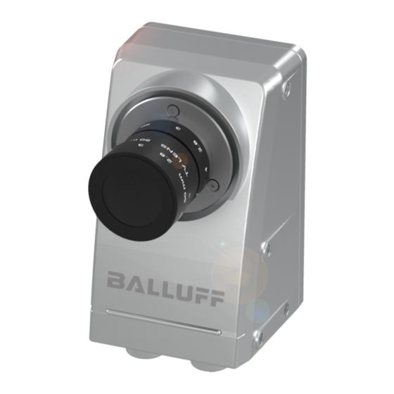
SMARTCAMERA IO 4 PRODUCT DESCRIPTION The Balluff SMARTCAMERA BVS SC is a camera for the acquisition and analysis of black- and white and color images. Application areas are optical identifications of codes and plain text, inspections for quality assurance and the measurement of objects. The camera can also be used in robot environments. -
Page 12: Scope Of Delivery
40 mm can be used here. For lenses up to 69 mm the long tube BAM PC-VS-023-1-01 (BAM02W0) may be used. For lenses up to 86 mm the long tube BAM PC-VS-023-1-02 (BAM039R) may be used. The following accessory groups complete the Balluff product range: • C-mount lenses (BAM LS-VS-004-C2/3-xx14-2) •... -
Page 13: Assembly
BVS SC-_1280Z00-70-000 SMARTCAMERA IO 4 PRODUCT DESCRIPTION NOTE Visit www.balluff.com for more information on available software and accessories. 4.2.1 Assembly The camera features 12 internal threads for installation at the location of use. Four threads each at the rear, the left and the right. This ensures secure and reliable mount- ing. - Page 14 The lateral screw connections have an M5 thread. The maximum engagement length is 5 mm. The maximum tightening torque is 2.6 Nm. WARNING The SMARTCAMERA and accessories must be firmly attached. Use only installation materials which are sufficiently dimensioned and ensure secure attachment. www. matrix-vision.com www.balluff.com...
-
Page 15: Product Specification
The SMARTCAMERA and accessories shall be supplied by limited energy in accordance to UL 61010-1 Third Edition, Sub. Clauses 9.4 or LPS in accordance to UL 60950-1 or Class 2 in accordance to UL 1310 or UL 1585. www. matrix-vision.com www.balluff.com... -
Page 16: Operating Conditions
80 % for temperatures up to 31 °C, decreasing linearly to 50 % at 40 °C Pollution degree Pollution degree 2 Vibration/shock was verified for the SMARTCAMERA – the C-mount lens used and its adjustment rings must be secured accordingly for operation. www. matrix-vision.com www.balluff.com... -
Page 17: Connections And Pin Assignment
9.4 or LPS in accordance to UL 60950-1 or Class 2 in accordance to UL 1310 or UL 1585. Power 5-pin M12 plug, A-coded Description Function +24V Supply voltage I/O 0 Input/output Ground I/O 1 Input/output Not used None. Pin may not be used. www. matrix-vision.com www.balluff.com... - Page 18 BI_DC – Bidirectional data, Pair C – BI_DC + Bidirectional data, Pair C + NOTE The cable must correspond at least to category 5e in accordance with EIA/TIA-568. Transfer in accordance with 1000BASE-T/100BASE-TX/10BASE- T is being supported. www. matrix-vision.com www.balluff.com...
- Page 19 The SMARTCAMERA and accessories shall be supplied by limited energy in accordance to UL 61010-1 Third Edition, Sub. Clauses 9.4 or LPS in accordance to UL 60950-1 or Class 2 in accordance to UL 1310 or UL 1585. www. matrix-vision.com www.balluff.com...
-
Page 20: Power
0 V (+V 100 mA max. – V Signal 1 24 V (V 100 mA max. Voltage drop V < 2 V < 10 μs Delay See also the guideline on digital inputs, EN 61131-2, Type 3. www. matrix-vision.com www.balluff.com... - Page 21 A 0 signal is being detected if the input is set to ground or is not connect- If an NPN device is to be connected to the input, then an external level converter must be connected upstream. Figure 3 Input connection www. matrix-vision.com www.balluff.com...
-
Page 22: Lan
1 Gigabit). This network connection is used to call up the web interface BVS Cockpit for the configuration. In addition, a communication channel is available to control the image analysis and to call up the generated result values. www. matrix-vision.com www.balluff.com... -
Page 23: I/O Light
The ring lighting is equipped with a M12 plug, so that it can be connected directly with the SMARTCAMERA. A complex wiring is not necessary. Naturally, other sensors/actuators can also be connected, the corresponding switching examples are located in the description of the power plug connector (see “Power”). www. matrix-vision.com www.balluff.com... -
Page 24: I/O
If the I/Os are configured as input, their signals are logically com- bined with OR. A 1 signal is recognized if a 1 signal is present ei- ther at I/O 0 of the power connection or I/O 0 of the I/O connection. www. matrix-vision.com www.balluff.com... - Page 25 If the error was removed, the output is again in normal operating state without a reset. It is also possible to use input and output functions at the same time. In the following example, I/O 0 is configured as output and I/O 1 as input. www. matrix-vision.com www.balluff.com...
- Page 26 If I/O 0 is configured as output, the output is connected with Common Out and the actua- tor, PLC input or similar is supplied with it if 1 is being output. The output is high- resistance if 0 is being output. www. matrix-vision.com www.balluff.com...
- Page 27 It is also possible to use input and output functions at the same time. In the following example, I/O 0 is configured as output and I/O 1 as input. Figure 12 NPN mode, I/O 0 configured as output and I/O 1 as input www. matrix-vision.com www.balluff.com...
-
Page 28: Display Elements
The outside of the camera can be cleaned with a soft cloth. Persistent dirt can be re- moved with a cloth that is first moistened with a soap solution and wrung out. → After wiping off the dirt spots, wipe the camera with a dry cloth. www. matrix-vision.com www.balluff.com... -
Page 29: First Steps
Since the different subnets, on the other hand, are connected via switches, the com- munication with the SMARTCAMERA is still possi- ble. Pertinent useful notes are located in the section “Network settings / LAN interface”. www. matrix-vision.com www.balluff.com... -
Page 30: Step 2: Turn On Smartcamera
More information about the configuration interface of the BVS Cockpit can be found in the software manual (BVS Cockpit manu- al) on the Balluff website and on the SMARTCAMERA. If there is already another SMARTCAMERA in the network, you can also connect with this SMARTCAMERA and change to any other SMARTCAMERA in the local network using this interface. - Page 31 BVS SC-_1280Z00-70-000 SMARTCAMERA IO 5 FIRST STEPS Figure 14 Display of all SMARTCAMERAs in the network www. matrix-vision.com www.balluff.com...
-
Page 32: Startup
BVS SC-_1280Z00-70-000 SMARTCAMERA IO 6 STARTUP Updating software The Balluff website regularly offers new software updates. These may include error fixes, speed optimizations or added functions. NOTE To get the maximum benefit from the SMARTCAMERA it is rec- ommended to regularly update the SMARTCAMERA with software updates. - Page 33 Never disconnect the camera from power during an update. This can result in irreparable damage to the SMARTCAM- ERA. After a few minutes the update will be finished and the Power LED will change to green. The SMARTCAMERA is now ready for use. www. matrix-vision.com www.balluff.com...
-
Page 34: Network Topologies
In the IO2 example, the I/O signals of the SMARTCAMERA are being analyzed by a controller. In addition, the SMARTCAMERA is controlled via the LAN connection. This allows the controller, e.g. to initiate the trigger or query the status of the SMARTCAM- ERA. Figure 15 IO2 topology www. matrix-vision.com www.balluff.com... -
Page 35: System Settings
LAN interface using TCP or UDP packets. → The pertinent protocol is described in the separate software manual ("BVS Cockpit Manual") under “Connection to the customer control system → Communication via UDP and TCP”. www. matrix-vision.com www.balluff.com... -
Page 36: Network Settings / Lan Interface
SMARTCAMERA is assigned the same address in every case. As an alter- native, the IP address can also be assigned manually (see the next section). NOTE To prevent address conflicts, no IP may be used more than once in the network! www. matrix-vision.com www.balluff.com... -
Page 37: Network Configuration Via Bvs Cockpit
Hardware line of the device which is used for this In-/Output. Inv. If activated the in/output gets inverted. Inverted in/outputs are interpreted as active on low voltage. If activated, the state of the in/output is shown with the camera LED. (only supported on smart cameras) www. matrix-vision.com www.balluff.com... - Page 38 NOTE After switching on and after switching to another inspection pro- gram the outputs are set as in the general settings: • 0 V if Inv. is not active • 24 V if Inv. is active www. matrix-vision.com www.balluff.com...
- Page 39 If the I/Os are configured as input, their signals are logically combined with OR. This means, a 1 signal is recognized if a 1 signal is present either at pin 2 of the power con- nection or pin 1 of the I/O connection. The same applies to I/O 1. www. matrix-vision.com www.balluff.com...
-
Page 40: Appendix
PC - used to resolve the NetBIOS name (http://sc-nnnnnnnnnde) of the smart camera. sible (especially The DNS server, of course, does not know the address http://sc-nnnnnnnnnde NetBIOS name with laptops) and responds with an error messsage. (http://sc- www. matrix-vision.com www.balluff.com... - Page 41 Repeat this step for every used "Get image" and "Find object" tool. Not every in- Connection to Possible approaches: spection result is the FTP server is Export only reports without images. transferred to the too slow. FTP server. www. matrix-vision.com www.balluff.com...
- Page 42 If Windows does not prompt for the login and password please use this command releases <= in a terminal window, replacing the host name with the correct value for your 2.3.0 and >= camera: 2.2.2); some- times also with error code cmdkey.exe /add:gemini-000110 /U:expert 0x80070035 /P:expert www. matrix-vision.com www.balluff.com...
-
Page 43: Type Code
SMARTCAMERA IO 7 APPENDIX Type code 1 2 3 4 5 6 7 8 9 1 B V S S C - Balluff Vision Solutions SMARTCAMERA Function type M: Monochrome sensor C: Color sensor 9-12 Resolution 1280: 1280 x 1024 pixels... - Page 44 GigE cable RJ45, M12, 2 m BCC06K7 BCC M418-0000-2A-044-VX8825-020 IO interface, M12, open, 2 m BCC032F BCC M415-0000-1A-003-PX0434-020 Power, M12, open, 2 m NOTE Other accessories for the BVS SC-… such as lenses, filters, lights or cables can be found at www.balluff.com. www. matrix-vision.com www.balluff.com...
- Page 45 Balluff GmbH Schurwaldstraße 9 73765 Neuhausen a.d.F. Germany Tel. +49 7158 173-0 Fax +49 7158 5010 balluff@balluff.de www.balluff.com...
Need help?
Do you have a question about the BVS SC Series and is the answer not in the manual?
Questions and answers