Sign In
Upload
Download
Table of Contents
Contents
Add to my manuals
Delete from my manuals
Share
URL of this page:
HTML Link:
Bookmark this page
Add
Manual will be automatically added to "My Manuals"
Print this page
×
Bookmark added
×
Added to my manuals
Manuals
Brands
Circutor Manuals
Measuring Instruments
Line-CVM-D32
Instruction manual
Circutor Line-CVM-D32 Instruction Manual
Power analyser
Hide thumbs
1
2
3
Table Of Contents
4
5
6
7
8
9
10
11
12
13
14
15
16
17
18
19
20
21
22
23
24
25
26
27
28
29
30
31
32
33
34
35
36
37
38
39
40
41
42
43
44
45
46
47
48
49
50
51
52
53
54
55
56
57
58
59
60
61
62
63
64
65
66
67
68
69
70
71
72
73
74
75
76
77
78
79
80
81
82
83
84
85
86
87
88
89
90
91
92
93
94
95
96
97
98
99
100
101
102
103
104
105
106
page
of
106
Go
/
106
Contents
Table of Contents
Bookmarks
Table of Contents
Safety Precautions
Disclaimer
Table of Contents
Contents
Revision Log
Symbols
1�- Verification Upon Reception
2�- Product Description
3�- Installation of the Device
3�1�- Preliminary Recommendations
3�2�- Installation
3�3�- PANEL ADAPTER 72 X 72 MM
3�4�- Device Terminals
3�5�- Expansion with Other Devices
3�5�1�- Line-M-EXT-PS POWER ADAPTER
3�5�2�- Installation
3�6�- Connection Diagrams
3�6�1�- 3-Phase Mains Measurement with 4-Wire Connection
3�6�2�- 3-Phase Mains Measurement with 3-Wire Connection
3�6�3�- 3-Phase Mains Measurement with 3-Wire Connection and Transformers with Aron
Connection
3�6�4�- 2-Phase Mains Measurement with 3-Wire Connection
3�6�5�- Single Phase Mains Measurement with 2-Wire Phase-To-Phase Connection
3�6�6�- Single Phase Mains Measurement with 2-Wire Phase-To-Neutral Connection
4�- Operation
4�1�- Measurement Parameters
4�1�1�- Quality Parameters
4�2� - Led Indicators
4�3�- Display
4�4�- Keyboard Functions
4�5�- Digital Outputs
5�- Display
5�1�- Instantaneous Value Menu
5�1�1�- Maximum and Minimum Values
5�2�- Energy Menu
5�3�- Maximum Demand Menu
5�3�1�- Maximum Values
5�4�- Quality Parameters Menu
5�5�- Voltage Harmonic Menu
5�6�- Current Harmonic Display
5�7�- Meter Menu
5�8�- Information Menu
5�9�- Input / Output Menu
6�- Configuration
6�1�- Measurement Configuration
6�1�1�- Primary and Secondary Voltage
6�1�2�- Primary and Secondary Current
6�1�3�- Quadrants and Measurement Convention
6�1�4�- Installation Type
6�1�5�- Calculation Periods
6�1�6�- Clear Maximums, Minimums and Maximum Demand
6�1�7�- Clear Energies and Delete All
6�1�8�- Harmonics and Currency Display
6�1�9�- Display Backlight and Password
6�2�- Quality Parameter Configuration
6�2�1�- Nominal Voltage and Frequency
6�2�2�- Overvoltage and Gaps
6�2�3�- Interruption and Hysteresis Value
6�2�4�- Clear Quality Parameters
6�3�- Device Clock Setting
6�3�1�- Date Format
6�3�2�- Date and Time
6�4�- Communications Configuration
6�4�1�- Peripheral Number and Transmission Speed
6�4�2�- Data Format and Measure Time
6�5�- Ratio Configuration
6�5�1�- Co Emissions in Consumption, Tariffs 1 and 2
6�5�2�- Co 2 Emissions in Consumption, Tariffs 3 and 4
6�5�3�- Cost of Consumed Energy in Consumption, Tariffs 1 and 2
6�5�4�- Energy Cost in Consumption, Tariffs 3 and 4
6�5�5�- Co Emissions in Generation, Tariffs 1 and 2
6�5�6�- Co
6�5�7�- Energy Cost in Generation, Tariffs 1 and 2
6�5�8�- Energy Cost in Generation, Tariffs 3 and 4
6�6�- Configuration of Digital Outputs 1 and 2
6�6�1�- Variable
6�6�2�- Maximum and Minimum Value
6�6�3�- Connection and Disconnection Delay
6�6�4�- Hysteresis and Status of Contacts
6�6�5�- Latch
6�6�6�- Energy Per Pulse and Contact Status
6�6�7�- Pulse
6�6�8�- Digital Output Manual Operation
7�- Rs-485 Communications
7�1�- Connections
7�2�- Modbus Protocol
7�2�1�- Modbus Query Example
7�3�- Modbus Memory Map
7�3�1�- Measurement Variables
7�3�2 �- Energy Variables
7�3�3�- Maximum Demand Variables
7�3�4�- Voltage and Current Harmonics
7�3�5�- Cost Variables
7�3�6�- Angle Variables
7�3�7�- Quality Event and Disturbance Counters
7�3�8�- Other Device Parameters
7�3�9�- Digital Outputs
7�3�10�- Device Configuration Variables
8�- Technical Features
9�- Maintenance and Technical Service
10 .- Guarantee
11�- Ce Certificate
Annex A.- Configuration Menu
Advertisement
Quick Links
Download this manual
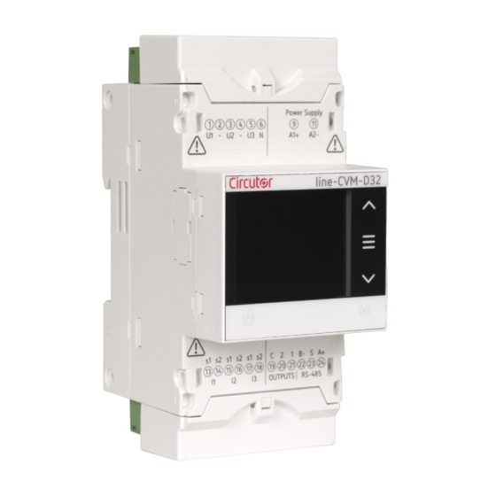
Power analyser
line-CVM-D32
INSTRUCTION MANUAL
(M237B01-03-22A)
Table of
Contents
Previous
Page
Next
Page
1
2
3
4
5
Advertisement
Table of Contents
Need help?
Do you have a question about the Line-CVM-D32 and is the answer not in the manual?
Ask a question
Questions and answers
Related Manuals for Circutor Line-CVM-D32
Measuring Instruments Circutor LM25-M Manual
(2 pages)
Measuring Instruments Circutor line-EDS-iMonitor Instruction Manual
Energy manager and visualizer (42 pages)
Measuring Instruments Circutor CVM-C4 Instruction Manual
Power analyzer (70 pages)
Measuring Instruments Circutor CVM-C10 Instruction Manual
Power analyzer (94 pages)
Measuring Instruments Circutor CVM-B100 Instruction Manual
Power analyzer (322 pages)
Measuring Instruments Circutor CVM-C11 Instruction Manual
Power analyzer (134 pages)
Measuring Instruments Circutor CVM-NRG96 User Manual
Power analyzer (39 pages)
Measuring Instruments Circutor MK-30-LCD Quick Start Manual
Single-phase energy meter (2 pages)
Measuring Instruments Circutor CVM 96 Instruction Manual
Cvm 96 series supply network analyzer (50 pages)
Measuring Instruments Circutor CVMk Series Instruction Manual
Supply network analyzer (64 pages)
Measuring Instruments Circutor AR5-L Instruction Manual
Supply network analyzer (20 pages)
Measuring Instruments Circutor DH96-CPP Manual
(22 pages)
Measuring Instruments Circutor CEM-C10 Instruction Manual
Multifunctional energy meter (36 pages)
Measuring Instruments Circutor DHB-402 Instruction Manual
(60 pages)
Measuring Instruments Circutor MYeBOX 150 Instruction Manual
Portable power analyzer (94 pages)
Measuring Instruments Circutor RGU-10 B Instruction Manual
Residual current device and monitor (34 pages)
This manual is also suitable for:
M58100
Table of Contents
Print
Rename the bookmark
Delete bookmark?
Delete from my manuals?
Login
Sign In
OR
Sign in with Facebook
Sign in with Google
Upload manual
Upload from disk
Upload from URL


Need help?
Do you have a question about the Line-CVM-D32 and is the answer not in the manual?
Questions and answers