Sign In
Upload
Download
Table of Contents
Contents
Add to my manuals
Delete from my manuals
Share
URL of this page:
HTML Link:
Bookmark this page
Add
Manual will be automatically added to "My Manuals"
Print this page
×
Bookmark added
×
Added to my manuals
Manuals
Brands
Circutor Manuals
Measuring Instruments
DHB-402
Instruction manual
Circutor DHB-402 Instruction Manual
Hide thumbs
1
2
3
Table Of Contents
4
5
6
7
8
9
10
11
12
13
14
15
16
17
18
19
20
21
22
23
24
25
26
27
28
29
30
31
32
33
34
35
36
37
38
39
40
41
42
43
44
45
46
47
48
49
50
51
52
53
54
55
56
57
58
59
60
page
of
60
Go
/
60
Contents
Table of Contents
Bookmarks
Table of Contents
Safety Precautions
Disclaimer
Contents
Table of Contents
1 Revision Log
1 �- Verification Upon Reception
2 �- Product Description
3�- Unit Installation
3�1�- Preliminary Recommendations
3�2�- Installation
3�3�- Unit Terminals
3�3�1�- List of Terminals, Dhb-402 Model
3�3�2�- List of Terminals, Dhb-424 Models
3�4�- Connection Diagram
3�4�1�- Connection of the Standard Analogue Signals
3 �4�2�- Connection for Measuring Temperature
4�- Operation
4�1�- Measuring Parameters
4�2�- Display
4�3�- Button Functions
4�4�- OPEN COLLECTOR OUTPUT, OC (DHB-424 Model)
4�5�- Regression of Non-Linear Equations
4�6�- Alarms
4�7�- Configuration
4�7�1�- Input Parameters
4�7�2�- Regression of Non-Linear Equations
4�7�3�- Display
4�7�4� Alarm 1
4�7�5� Alarm 2
4�7�6� Alarm 3
4�7�7� Alarm 4
4�7�8� OUTPUTS (DHB-424 Model)
4�7�9� Service
4�8�- COMMUNICATIONS (DHB-424 Model)
4�8�1�- Connections
4�8�2�- Modbus Protocol
4 �8�3�- Modbus Memory Map
5 �- Technical Features
6 �- Maintenance and Technical Service
7 �- Warranty
8�- Ce Certificate
Appendix A: Display Messages
Advertisement
Quick Links
Download this manual
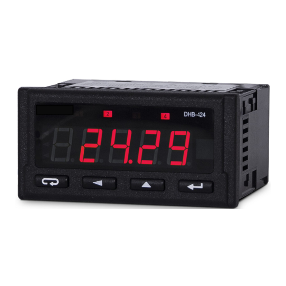
Indicator for process signals,
temperature and resistance
DHB-402 DHB-424
INSTRUCTION MANUAL
(M045B01-03-21A)
Table of
Contents
Previous
Page
Next
Page
1
2
3
4
5
Advertisement
Table of Contents
Need help?
Do you have a question about the DHB-402 and is the answer not in the manual?
Ask a question
Questions and answers
Related Manuals for Circutor DHB-402
Measuring Instruments Circutor DHC-96 Aac Instruction Manual
Ac ammeter (46 pages)
Measuring Instruments Circutor DHB-102 Instruction Manual
Impulse, frequency and time meter (80 pages)
Measuring Instruments Circutor DHB-302 Instruction Manual
Single-phase vac analyzer (70 pages)
Measuring Instruments Circutor DHB-324 Instruction Manual
Single-phase vac analyzer (70 pages)
Measuring Instruments Circutor DHB-424 Instruction Manual
(60 pages)
Measuring Instruments Circutor DHC-96 CPM 1500 Instruction Manual
Dc multimeter (56 pages)
Measuring Instruments Circutor DH96-CPP Manual
(22 pages)
Measuring Instruments Circutor DHC-96 mAdc Instruction Manual
Dc ammeter (50 pages)
Measuring Instruments Circutor DHC-96 Adc Instruction Manual
Dc ammeter (50 pages)
Measuring Instruments Circutor DHC-96 Vac Instruction Manual
Ac voltmeter (46 pages)
Measuring Instruments Circutor DHC-96 mVdc Instruction Manual
Dc voltmeter (52 pages)
Measuring Instruments Circutor DHC-96 LVdc Instruction Manual
Dc voltmeter (52 pages)
Measuring Instruments Circutor DHC-96 HVdc Instruction Manual
Dc voltmeter (52 pages)
Measuring Instruments Circutor DHC-96 Vdc Instruction Manual
Dc voltmeter (52 pages)
Measuring Instruments Circutor DCP-96 Aac Instruction Manual
Ac ammeter (30 pages)
Measuring Instruments Circutor DCB-72 Vac Instruction Manual
Ac voltmeter (36 pages)
This manual is also suitable for:
Dhb-424
Table of Contents
Print
Rename the bookmark
Delete bookmark?
Delete from my manuals?
Login
Sign In
OR
Sign in with Facebook
Sign in with Google
Upload manual
Upload from disk
Upload from URL


Need help?
Do you have a question about the DHB-402 and is the answer not in the manual?
Questions and answers